ILLKO REVEXmax S User manual
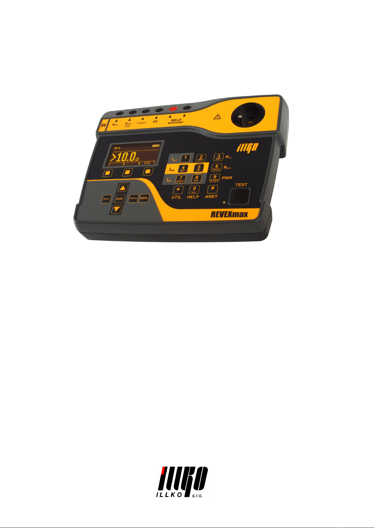
REVEXmax S
REVEXmax W
User’s Manual
Version 1.1 05/2019

Copyright c
2019, ILLKO, s.r.o.
All Rights Reserved. Copying or any other way of duplication of this document or its parts is
allowed with antecedent written permission of ILLKO, s.r.o. only.

REVEXmax - User’s Manual Contents
Contents
1 Introduction 6
1.1 Safety ................................... 6
1.2 Performance REVEXmax . . . . . . . . . . . . . . . . . . . . . . . . 7
1.3 Appliedstandards............................. 7
1.4 Termsanddefinitions........................... 8
2 Description of the instrument 9
2.1 Generaldescription............................ 9
2.2 Terminals ................................. 10
2.3 Keyboard ................................. 13
2.4 Additionalfunctions ........................... 13
2.5 Display of information . . . . . . . . . . . . . . . . . . . . . . . . . . 13
2.6 GraphicOLEDdisplay.......................... 14
2.7 Selection of the items in Menu or List . . . . . . . . . . . . . . . . . . 14
2.8 Users interface symbols . . . . . . . . . . . . . . . . . . . . . . . . . . 15
2.9 Abbreviations............................... 16
2.10Includedintheset ............................ 16
2.11Optionalaccessories............................ 17
3 Putting into operation 18
3.1 Connecting to mains outlet . . . . . . . . . . . . . . . . . . . . . . . . 18
3.2 Self-test .................................. 19
3.3 Helpscreens................................ 19
4 Measurements 20
4.1 Selection of the function . . . . . . . . . . . . . . . . . . . . . . . . . 20
4.2 Measurement mode control . . . . . . . . . . . . . . . . . . . . . . . . 20
4.2.1 Measurement mode . . . . . . . . . . . . . . . . . . . . . . . . 20
4.2.2 HOLDfunction.......................... 21
4.2.3 Measurement of apparent power consumption . . . . . . . . . 21
4.3 Earthbond-Rpe............................. 22
4.3.1 Test lead resistance compensation . . . . . . . . . . . . . . . . 22
4.3.2 Protective earth resistance . . . . . . . . . . . . . . . . . . . . 23
4.4 Insulation resistance - Riso . . . . . . . . . . . . . . . . . . . . . . . . 24
4.5 Alternative method - IaltEq . . . . . . . . . . . . . . . . . . . . . . . 26
4.5.1 Protective class I appliances . . . . . . . . . . . . . . . . . . . 26
4.5.2 Protective class II appliances - alternative touch leakage current 26
4.6 PE current during operation – IdirEq / differential leakage current -
IdifEq ................................... 27
4.6.1 Protective class I one-phase appliances . . . . . . . . . . . . . 27
4.6.2 Three-phase and hard-wired appliances . . . . . . . . . . . . . 28
4.7 Touch leakage current - IdirTouch / IdifTouch / IdirW . . . . . . . . 29
4.7.1 Protective class II appliances . . . . . . . . . . . . . . . . . . 29
4.7.2 Protective class I appliances . . . . . . . . . . . . . . . . . . . 29
4.7.3 Welding equipment output leakage current . . . . . . . . . . . 30
c
2019 ILLKO, s.r.o. www.illko.cz Page 3

REVEXmax - User’s Manual Contents
4.8 Apparent power, mains voltage and current consumption - Power . . 31
4.8.1 Power, mains voltage and current consumption in Test Socket 31
4.8.2 Measuring of power and current consumption by means of
currentclamp........................... 32
4.9 Automatic testing extension power supply cords . . . . . . . . . . . . 33
4.10 Welding equipment output voltage - Uo . . . . . . . . . . . . . . . . . 34
4.11 External voltage measurement - Voltmeter . . . . . . . . . . . . . . . 34
5 Database operations 35
5.1 Storing measurement data . . . . . . . . . . . . . . . . . . . . . . . . 35
5.2 The structure of the data memory . . . . . . . . . . . . . . . . . . . . 35
5.3 Enteringcharacters............................ 36
5.4 Identification number of device under test (ID) . . . . . . . . . . . . . 36
5.5 Working with test results . . . . . . . . . . . . . . . . . . . . . . . . . 37
5.5.1 Viewing a list of tested DUTs . . . . . . . . . . . . . . . . . . 37
5.5.2 Searching for stored DUTs . . . . . . . . . . . . . . . . . . . . 38
5.5.3 Creating a new DUT file . . . . . . . . . . . . . . . . . . . . . 38
5.5.4 Deleting a DUT from the main memory . . . . . . . . . . . . 38
5.5.5 Modification of the ID number . . . . . . . . . . . . . . . . . . 39
5.5.6 Viewing measured values and evaluation . . . . . . . . . . . . 39
5.5.7 Modification of measured values and evaluation . . . . . . . . 40
5.6 Testsequences............................... 40
5.6.1 Description of the test sequence . . . . . . . . . . . . . . . . . 40
5.6.2 Creating a test sequence . . . . . . . . . . . . . . . . . . . . . 40
5.6.3 Assigning a test sequence to appliance . . . . . . . . . . . . . 41
5.6.4 Using the test sequence . . . . . . . . . . . . . . . . . . . . . . 41
6 Instrument main menu 42
6.1 Mainmenustructure........................... 42
6.2 Menu-DUTproperties.......................... 42
6.2.1 Menu - Measured values . . . . . . . . . . . . . . . . . . . . . 42
6.2.2 Menu - Visual inspection result . . . . . . . . . . . . . . . . . 42
6.2.3 Menu - Functional test result . . . . . . . . . . . . . . . . . . 42
6.2.4 Menu - Measurement result . . . . . . . . . . . . . . . . . . . 43
6.3 Menu - Test sequences . . . . . . . . . . . . . . . . . . . . . . . . . . 43
6.4 Menu-Emptyfile............................. 43
6.5 Menu-Setup ............................... 44
6.5.1 Menu - System info . . . . . . . . . . . . . . . . . . . . . . . . 44
6.5.2 Menu-Self-test.......................... 44
6.5.3 Menu - Date of next calibration . . . . . . . . . . . . . . . . . 44
6.5.4 Menu - Erase database . . . . . . . . . . . . . . . . . . . . . . 44
6.5.5 Menu - Measurement locking . . . . . . . . . . . . . . . . . . . 44
6.5.6 Menu - Save last method . . . . . . . . . . . . . . . . . . . . . 44
6.5.7 Menu - Date and Time . . . . . . . . . . . . . . . . . . . . . . 45
6.5.8 Menu-Keysbeep......................... 45
6.5.9 Menu-Volume .......................... 45
6.5.10 Menu-Language......................... 45
c
2019 ILLKO, s.r.o. www.illko.cz Page 4

REVEXmax - User’s Manual Contents
7 Additional information 46
7.1 Communication – data transfer . . . . . . . . . . . . . . . . . . . . . 46
7.2 Messages on the display . . . . . . . . . . . . . . . . . . . . . . . . . 46
7.2.1 Warningmessages......................... 46
7.2.2 Operational information . . . . . . . . . . . . . . . . . . . . . 52
7.2.3 Setting information . . . . . . . . . . . . . . . . . . . . . . . . 54
7.2.4 Database information . . . . . . . . . . . . . . . . . . . . . . . 55
7.3 Reset of the instrument . . . . . . . . . . . . . . . . . . . . . . . . . . 55
7.4 To use special accessories . . . . . . . . . . . . . . . . . . . . . . . . . 56
7.4.1 Carrying bag for instrument (P 6150) . . . . . . . . . . . . . . 56
7.4.2 Adapter for testing extension power supply cords (P 8030) . . 58
7.4.3 Set of adapters ATP for automatic testing extension power
supply cords (P 8080) . . . . . . . . . . . . . . . . . . . . . . 58
7.4.4 Three-phase adapter (P 8015-8018) . . . . . . . . . . . . . . . 59
7.5 Maintenance................................ 60
7.6 Fuse .................................... 60
7.7 Recurrent tests and testing after repair . . . . . . . . . . . . . . . . . 61
7.8 Calibration and service . . . . . . . . . . . . . . . . . . . . . . . . . . 62
7.9 Ecology .................................. 62
8 Technical specification 63
8.1 Generaldata ............................... 63
8.2 Functions ................................. 63
8.2.1 Earthbond ............................ 63
8.2.2 Insulation resistance . . . . . . . . . . . . . . . . . . . . . . . 64
8.2.3 Alternative leakage current . . . . . . . . . . . . . . . . . . . . 64
8.2.4 Direct leakage current . . . . . . . . . . . . . . . . . . . . . . 64
8.2.5 Differential leakage current . . . . . . . . . . . . . . . . . . . . 65
8.2.6 Leakage current by means of three-phase adapter . . . . . . . 65
8.2.7 Apparentpower.......................... 65
8.2.8 Mains voltage UL-N ........................ 65
8.2.9 Current consumption . . . . . . . . . . . . . . . . . . . . . . . 65
8.2.10 Current consumption by means of current clamp . . . . . . . . 66
8.2.11 Apparent power by means of current clamp . . . . . . . . . . 66
8.2.12 External voltage DC (WELD variant only) . . . . . . . . . . . 66
8.2.13 External voltage AC (WELD variant only) . . . . . . . . . . . 66
8.2.14 Welding equipment output voltage (WELD variant only) . . . 66
c
2019 ILLKO, s.r.o. www.illko.cz Page 5
REVEXmax - User’s Manual 1 Introduction
1 Introduction
1.1 Safety
WARNING
Read this User’s Manual carefully and completely and follow
all instructions contained therein. If not, the use of the in-
strument may be dangerous for the operator, devices under
test or for the instrument!
If there is reason to believe that safe operation has become impossible,
put the instrument out of operation and secure it against any unin-
tended operation. Safe operation must be presumed to be no longer
possible, if:
•The instrument does not operate properly any longer.
•The instrument, cables, connectors, plugs or accessories exhibits
visible damages.
•The instrument was stored in unfavourable conditions for a long
period.
•The instrument was exposed to extraordinary stress caused by
transport.
WARNING
•Make sure that the instrument, measuring cables and all other
accessories are in flawless condition, e.g. no damaged insulation,
no broken cables or plugs etc.
•Make sure that the AC outlet is easily accessible. If some trouble
or malfunction occurs, immediately disconnect the REVEXmax
adaptor from the outlet.
•If the equipment is used in a manner not specified by the manu-
facturer, the device’s protection may be compromised.
•The instrument may only be powered from a 230 V / 50 Hz
grounded mains outlet, which is protected with a fuse or circuit
breaker with a maximum rating of 16 A.
•In order to check the proper PE connection to a mains outlet,
REVEXmax generates a continuous current of ca. 1.5 mA /
50 Hz to the PE conductor. This test current can activate the
insulation monitoring device in IT systems.
•Only a trained, skilled person, who is familiar with hazardous
voltage operations, can handle the REVEXmax. Unexpected
hazardous voltages can occur on devices under test (dangerously
charged capacitors, etc.).
c
2019 ILLKO, s.r.o. www.illko.cz Page 6
REVEXmax - User’s Manual 1 Introduction
WARNING
•It is necessary to respect all safety regulations applicable to the
particular measurement.
•Test Socket 1of the REVEXmax must not be used for contin-
uously powering the appliance. It is intended for test purposes
only; max. test duration is 25 min @ ≤12 A and 60 s @ 12÷16 A.
•The functional test may only be performed after the DUT has
successfully passed the safety test.
•Dangerous voltage or mains voltage may be present on Test
Socket 1during some tests.
•Devices under test which are connected to Test Socket 1of the
REVEXmax can be powered by mains voltage during some tests.
The appliance can thus be activated.
•The PE terminal is connected to the PE terminal of Test Socket
1. When using the REVEXmax, do not connect any voltage to
the terminal PE. If connected, there is a danger of electric shock
or damage to the REVEXmax.
•Use only standard or optional accessories supplied with the
REVEXmax by your distributor.
The figures in this manual are only illustrative and may vary slightly
from the actual state or the version on your instrument.
1.2 Performance REVEXmax
The REVEXmax S (STANDARD) / REVEXmax W (WELD) is a professional,
compact, portable analyzer, designed to verify the electrical safety of appliances or
arc welding equipments (WELD variant only). The REVEXmax has an extraordi-
nary wide scope of use thanks to a lot of optional accessories, which enable testing
practically any portable or hard-wired, one-phase or three-phase appliance.
1.3 Applied standards
•EMC ..............................................EN 55011:2009+A1:2010
EN 61326-1:2013
EN 61000-4-2:2009
EN 61000-4-3:2006+A1:2007+A2:2010
EN 61000-4-4:2012
EN 61000-4-5:2014
EN 61000-4-6:2014
EN 61000-4-11:2004
EN 61000-3-2:2014
EN 61000-3-3:2013
c
2019 ILLKO, s.r.o. www.illko.cz Page 7
REVEXmax - User’s Manual 1 Introduction
•LVD ........................................................EN 61010:2010
EN 61010-2-030:2010
The REVEXmax is designed to perform electrical safety testing based on
•EN 61557
•EN 60974-4
1.4 Terms and definitions
Plugged-in equipment
Term meaning electrically connected to the supply mains by means of a connection
than can be detached without the use of a tool.
Permanently installed
Term meaning electrically connected to the supply mains by means of a permanent
connection than can only be detached by the use of a tool.
Accessible conductive part
Part of the equipment, which is accessible to the operator.
Mains part
The part of electrical equipment forming a circuit that is intended to be connected
to the supply mains.
Protective earth conductor
Conductor to be connected between the protective earth terminal and an external
protective earthing system.
Power supply cord
Flexible cord, fixed to or assembled with electrical equipment for connection to
supply mains.
ID number (ID)
Unique ID number for the DUT.
Hazardous voltage.
Warning concerning a point of danger! Read User’s Manual and
observe all precautions!
Hint, notice.
c
2019 ILLKO, s.r.o. www.illko.cz Page 8

REVEXmax - User’s Manual 2 Description of the instrument
2 Description of the instrument
2.1 General description
The REVEXmax S (STANDARD) / REVEXmax W (WELD) instrument is de-
signed to verify the safety of electrical appliances in general. All AC measurements
are measured by the method TRMS (true rms), and for some measurements the
DC component value can be displayed. Measured circuits meet the requirements
of EN 61557 and EN 60974-4 (requirements for measuring circuits), including the
required input characteristics.
The REVEXmax performs the following tests:
•Earth bond test >1 A AC
•Insulation resistance test 500 V DC and 250 V DC
•Alternative (substitute) leakage current
•PE current during operation and touch leakage current
•Differential leakage current and touch leakage current
•Apparent power
•Mains voltage
•Current consumption
•Welding equipments output voltage and leakage current (WELD variant only)
•External voltage (WELD variant only)
With additional equipment can be measured:
•measurement of PE current during operation of three-phase portable appliance
by means of optional adapters
•measurement of differential leakage current of three-phase portable appliance
by means of optional adapters
•measurement of PE current during operation by means of current clamp
•measurement of differential leakage current by means of current clamp
•measurement of current consumption by means of current clamp
•measurement of apparent power by means of current clamp
The REVEXmax has furthermore additional features, which improve the safety of
both the operator and the DUT. These include:
•check for dangerous contact voltage on the PE of power outlet (before the
start of the measurement)
•check if the PE of the power outlet is grounded (before the start of the mea-
surement)
•automatic check for leakage current amplitude of the device under test
•check of the appliance’s current with automatic switch off the Test Socket 1:
0÷12 A . . . . . . . . . . . . . . . . . . . . max. 25 min
12 ÷16 A . . . . . . . . . . . . . . . . . . . max. 60 sec
•manual self-test
c
2019 ILLKO, s.r.o. www.illko.cz Page 9
REVEXmax - User’s Manual 2 Description of the instrument
Features and highlights:
•test results can be saved under an ID number which is unequivocally assigned
to the respective DUT (barcode)
•the test structures created at the PC software can be loaded into the REVEX-
max
•measurement data saved to the test instrument can be imported to PC software
via the USB port and reports can be generated
•user-defined test sequences created at the PC software
•user-defined report templates created at the PC software
2.2 Terminals
1. Test Socket for connection of tested appliance’s power supply cord
2. Voltmeter [−]- external voltage test terminal (WELD variant only)
3. Voltmeter [+] - external voltage test terminal (WELD variant only)
4. PE – terminal for connecting the exposed conductive part of the tested appli-
ance (the terminal is connected to the PE terminal of Test Socket 1)
5. ITOUCH – touch leakage current test terminal
6. RISO /IALT – insulation resistance / alternative leakage current test terminal
7. RPE – earth bond test terminal
8. EXT input - current clamp / three-phase adapter / other adapters connector
9. Fuse F 16 A / 500 V
10. USB - socket type A for connection USB 2.0 Full Speed HID (Human Interface
Device), e.g. barcode scanner
11. USB – socket type B, PC connection
12. Power supply cord
WARNING
•Do not connect any external voltage to any terminal or connector.
The only exception is the power supply cord 12 which is intended
for powering the REVEXmax from the 230 V / 50 Hz mains
outlet.
•Max. load on Test Socket 1is 16 A (limited in time).
•Use original accessories only.
•Do not connect any external voltage between RPE terminal and
the PE in Test Socket 1or PE terminal.
c
2019 ILLKO, s.r.o. www.illko.cz Page 10


REVEXmax - User’s Manual 2 Description of the instrument
2.3 Keyboard
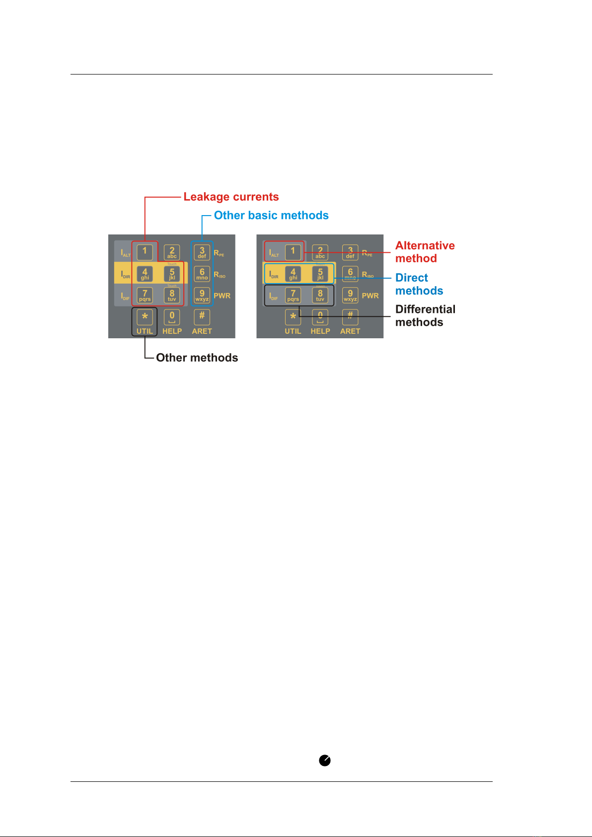
13. [1 IALT]– Alternative leakage current
14. [2] – without function
15. [3 RPE]– Earth bond test
16. [4 IDIR]– Direct leakage current (PE current during operation)
17. [5 IDIR TOUCH]– Enclosure (touch) leakage currents (direct method)
18. [6 RISO]– Insulation resistance, selection of test voltage 500 V / 250 V DC
19. [7 IDIF]– Differential leakage current
20. [8 IDIF TOUCH]– Enclosure (touch) leakage currents (differential method)
21. [9 Power] – Apparent power consumption, current, mains voltage
22. [* UTIL] – Other measuring method:
- Welding equipment output leakage current (WELD variant only)
- Welding equipment output voltage (WELD variant only)
- Voltmeter (WELD variant only)
23. [TEST] – Starts measurement
2.4 Additional functions
24. [0 HELP] – display the help for selected measurement
25. [# ARET] – lock the TEST key
26. [N]– scroll up
27. [H]– scroll down, hold displayed data
28. [save] – save measured values
29. [menu] – main menu
30. [ent] – ENTER, find DUT according to ID, other functions depending on
context
31. [esc] – ESCAPE, other functions depending on context
32. Context menu buttons - actual function is displayed above the button
2.5 Display of information
33. Graphic OLED display
34. LED indicator for measuring status
c
2019 ILLKO, s.r.o. www.illko.cz Page 13
REVEXmax - User’s Manual 2 Description of the instrument
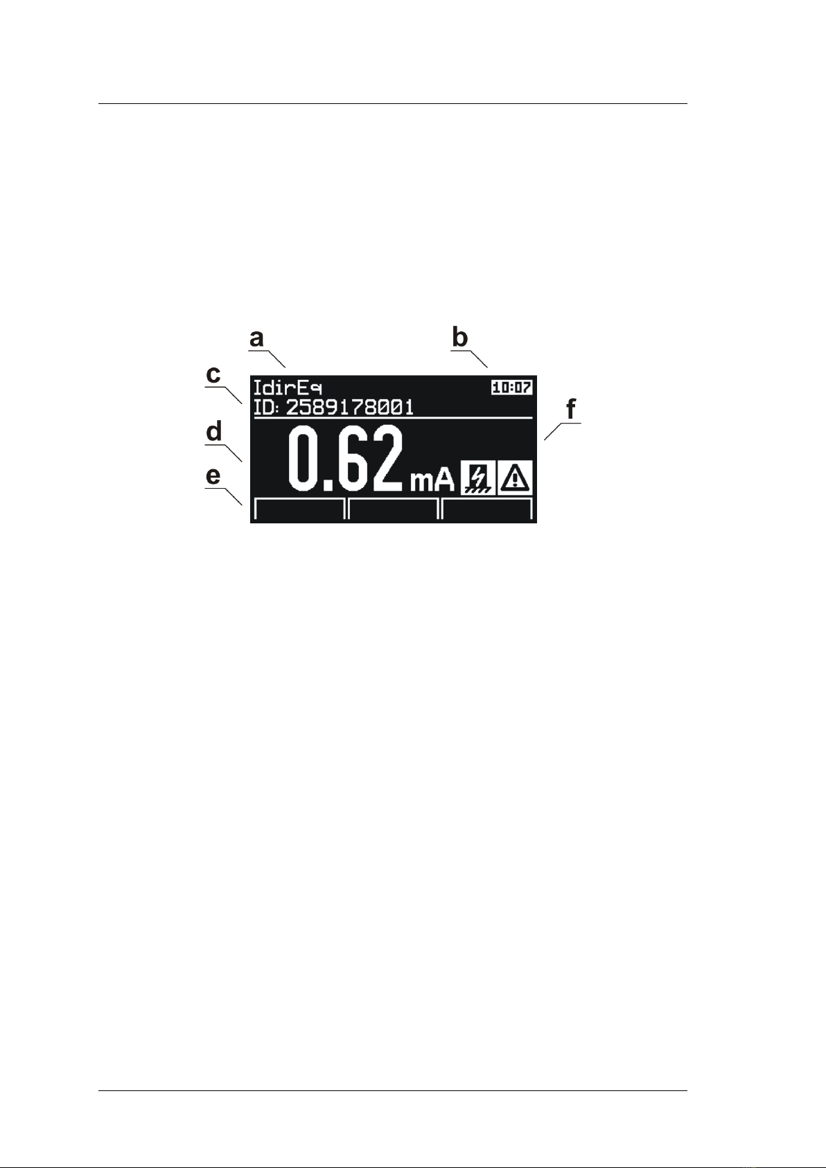
2.6 Graphic OLED display
a) Measured function
b) Real time clock / Measuring is in progress
c) Selected method and ID of DUT
d) Measured value
e) Actual function of context button (32)
f) Warning, notice, additional information
Figure 3: Graphic OLED display
2.7 Selection of the items in Menu or List
The item is selected using buttons:
[N]and [H]
Faster scroll in the lists:
[Page-] and [Page+]
c
2019 ILLKO, s.r.o. www.illko.cz Page 14
REVEXmax - User’s Manual 2 Description of the instrument
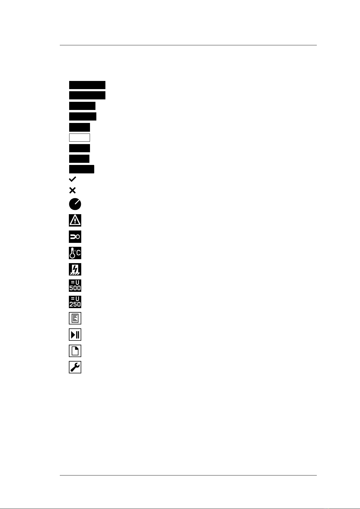
2.8 Users interface symbols
ARET lock the TEST key
AUT.ARET automatic lock the TEST key
HOLD displayed value is held
L-N xL-N reversal in Test Socket 1
SEQ test sequence is active
CAL test lead resistance compensation is finished
CAL the value of compensation is higher than measured value
ESC press [esc] key
TEST press [TEST] key
the selection is active, self-test passed
the selection is not active, self-test failed
measuring is in progress
warning – Test Socket 1energizing
plug external accessories
inner temperature is increasing when measuring PE resistance
notice - DUT must be isolated from ground
test voltage 500 V DC
test voltage 250 V DC
menu Properties of DUT
menu Test sequences
menu Empty file of DUT
menu Setup
c
2019 ILLKO, s.r.o. www.illko.cz Page 15

REVEXmax - User’s Manual 2 Description of the instrument
2.9 Abbreviations
Lphase conductor
Nneutral conductor
PE protect earth conductor
ALT alternative (substitute) method
DIF differential method
DIR direct method
Eq equipment
RL-N reversal
Ext external
Touch touch
Mmains part
Wwelding part
socket connection: Test Socket 1
RPE connection: terminal RPE (Note: also applies to the other
terminals)
2.10 Included in the set
The set includes all accessories necessary for testing 230 V / 50 Hz appliances
equipped with a movable power supply cord.
The set includes:
•The measuring instrument REVEXmax
•P 2011 - Test lead, black, 2 m
•P 3011 - Test tip black
•P 2014 - Test lead, red, 2 m (WELD variant only)
•P 4016 - Crocodile clip, red (WELD variant only)
•USB cable A-B
•Spare fuse F 16 A / 500 V, 32 x 6.3 mm, 2 pcs
•CD (User’s Manual + SW for PC)
•User’s Manual
•Calibration certificate
•Warranty card
c
2019 ILLKO, s.r.o. www.illko.cz Page 16

REVEXmax - User’s Manual 2 Description of the instrument
2.11 Optional accessories
Carrying bag:
•P 6150 - Bag for instrument
Measuring cables and adapters:
•P 2012 - Test lead, blue, 2 m
•P 2020 - Test lead, black, 5 m
•P 3012 - Test tip, blue
•P 3031 - Test tip (2 mm), black
•P 4011 - Crocodile clip, black
•P 4012 - Crocodile clip, blue
•P 8030 - Adapter for testing extension power supply cords
Special accessories:
•P 8010 - Current clamp transformer
•P 8015 - Three-phase adapter, 16 A socket, 5 contacts
•P 8016 - Three-phase adapter, 16 A socket, 4 contacts
•P 8017 - Three-phase adapter, 32 A socket, 5 contacts
•P 8018 - Three-phase adapter, 32 A socket, 4 contacts
•P 8080 - Set of adapters ATP for automatic testing ext. power supply cords
•P 9010 - Wireless barcode scanner (CCD) BT/USB 2.0 Full Speed
•P 9022 - Barcode scanner (CCD) USB 2.0 Full Speed
•P 9025 - RFID reader USB 2.0 Full Speed
Spare parts:
•D 0010 - Set of 10 pcs spare fuses F 16 A / 500 V, 32 x 6.3 mm
c
2019 ILLKO, s.r.o. www.illko.cz Page 17
REVEXmax - User’s Manual 3 Putting into operation
3 Putting into operation
3.1 Connecting to mains outlet
If the mains outlet, mains cable, instrument’s case or acces-
sories are damaged, do not connect the REVEXmax to the
mains outlet!
If Idir and Idif is being measured, use the grounded mains
outlet only to supply the instrument!
The REVEXmax can only be powered from 230 V / 50 Hz, which is protected
with a fuse or circuit breaker with a maximum rating of 16 A. The instrument is
automatically switched on after plugging into the mains outlet. Disconnect any
DUT while connecting/disconnecting the REVEXmax to/from the mains outlet!
The REVEXmax automatically tests the protective PE (ground) pin
of the mains outlet. If the PE connection is inadequate, then the mes-
sage (PE error) is displayed.
In order to check the proper PE connection to a mains outlet, the
REVEXmax generates a continuous current of ca. 1.5 mA / 50 Hz to
the PE conductor. This test current can activate the insulation moni-
toring device in IT systems.
If the REVEXmax is connected to an IT earthing system, it is possible
to measure – e.g. Rpe, Riso and Ialt.
If dangerous contact voltage arises on the PE, then the (PE error)
indicator lights up when the operator presses the key [TEST]. If op-
erator presses the [TEST] key after this, the measurement will not
start.
WARNING
If the test result for the ground pin of the mains outlet is
unsatisfactory (in TT or TN systems), the outlet must be
repaired before you plug in the REVEXmax to the outlet
again!
c
2019 ILLKO, s.r.o. www.illko.cz Page 18
REVEXmax - User’s Manual 3 Putting into operation
3.2 Self-test
It can sometimes be difficult to identify if the measuring instrument does not work
properly, especially when measuring current leakage. The REVEXmax therefore has
built in the possibility to promptly test the basic functionality. The functionality of
the following functions can be tested:
•Insulation resistance
•Measurement of alternative (substitute) leakage current
•Measurement of PE current during operation
•Measurement of differential leakage current
WARNING
•Disconnect DUT before the REVEXmax self-test!
•This test does not substitute for calibration!
•The REVEXmax has to be connected to TT or TN mains.
The test result is displayed on the display using the symbols pass / fail. Test
proceeds as follows:
•Disconnect the DUT.
•Press the [menu] key and release it.
•Use the [H]key to select (Setup), press the [ent] key for confirmation.
•Use the [H]key to select (Self-test), press the [ent] key for confirmation.
•Press the [TEST] key. The test will then start; after it is finished, the results
are displayed: (self-test passed) or (self-test failed).
•The correct values are:
–RisoM-PE: 2.00 ±0.05 MΩ
–IaltEq: 0.10 ±0.01 mA
–IdirEq: 0.10 ±0.01 mA
–IdifEq: 0.10 ±0.01 mA
Contact service if the test results differ from the ones described above.
3.3 Help screens
The help screens are available in all functions. The Help screens contain schematic
diagrams for illustrating how to properly connect the instrument for electric instal-
lation. After selecting the measurement you want to perform, press the [0 HELP]
(once or repetitively) key in order to see the associated Help screens.
Press the [0 HELP] or [esc] to leave the Help.
c
2019 ILLKO, s.r.o. www.illko.cz Page 19
REVEXmax - User’s Manual 4 Measurements
4 Measurements
4.1 Selection of the function
The measured function can be selected automatically in sequence mode (see chap-
ter 5.6) or manually (see Figure 4).
Figure 4: Keyboard
4.2 Measurement mode control
The beginning, process and ending of measurements are controlled by the [TEST]
key. If the [esc] key was pressed during the measurement, then it will be cancelled
(the measured value is not saved).
4.2.1 Measurement mode
The measurement can start in four different measurement modes:
•One measuring cycle – after the [TEST] key is pressed and released, one
measuring cycle starts and is completed after a few seconds. The result of the
measurement is displayed.
•Continuous measurement – press the [TEST] key; measurement is in progress
and current measured values are displayed until the [TEST] key is released.
The result of the measurement is displayed.
•Locking the measurement - press the [# ARET] key and then press the
[TEST] key. Then release both keys. The measurement is in progress and the
current measured values are displayed until the [TEST] key is again pressed
and released. Reverse steps are possible too: press the [TEST] key and then
press the the [# ARET] key.
•Automatically locking the measurement – this function can be set in the menu
Setup. Measuring is similar to Locking the measurements but the [# ARET]
key is not used.
Measuring in process is indicated by the symbol .
c
2019 ILLKO, s.r.o. www.illko.cz Page 20
This manual suits for next models
1
Table of contents
Other ILLKO Test Equipment manuals


Popular Test Equipment manuals by other brands


Redtech
Redtech TRAILERteck T05 user manual

Venmar
Venmar AVS Constructo 1.0 HRV user guide

Test Instrument Solutions
Test Instrument Solutions SafetyPAT operating manual

Hanna Instruments
Hanna Instruments HI 38078 instruction manual

Kistler
Kistler 5495C Series instruction manual

Waygate Technologies
Waygate Technologies DM5E Basic quick start guide

StoneL
StoneL DeviceNet CK464002A manual

Seica
Seica RAPID 220 Site preparation guide

Kingfisher
Kingfisher KI7400 Series Training manual

Kurth Electronic
Kurth Electronic CCTS-03 operating manual

SMART
SMART KANAAD SBT XTREME 3G Series user manual

Agilent Technologies
Agilent Technologies BERT Serial Getting started