CESVA DC112k User manual

User’s Manual
DC112k / DC112a
Dosimeter / Dosimeter Spectrum Analyser
M_DC112kDC112a_v0009_20170113_EN

MANUAL DEL USUARIO
USER’S MANUAL
BENUTZERHANDBUCH
MANUEL D'INSTRUCTIONS
MANUALE D’USO
MANUAL DE L’USUARI

DC112k/DC112
User’s manual
1
ENGLISH
1. GENERAL DESCRIPTION................................................................................................ 3
1.1 Activation of the frequency analysis in octaves module for the DC112k ....................... 4
1.2 Main Characteristics of the DC112k/DC112a ............................................................... 4
1.3 Functions ..................................................................................................................... 5
1.4 Description of the DC112k/DC112a.............................................................................. 6
1.5 Screen.......................................................................................................................... 8
1.6 Use of the keypad ........................................................................................................ 8
2. USING THE DC112k/DC112a..........................................................................................10
2.1 Initial steps..................................................................................................................10
2.1.1 Material and documentation..................................................................................10
2.1.2 DC112k/DC112a Power source ............................................................................10
2.1.3 Connection and disconnection of the microphone.................................................11
2.1.4 Fixing the DC112k/DC112a on the user (worker)..................................................12
2.2 Beginning a measurement...........................................................................................12
2.2.1 Switching on the DC112k/DC112a........................................................................12
2.2.2 Display screen selection........................................................................................12
2.2.3 Testing the DC112k/DC112a ................................................................................14
2.3 Measuring with the DC112k/DC112a ..........................................................................15
2.3.1 Prior adjustments..................................................................................................16
2.3.2 Beginning a measurement ....................................................................................18
2.3.3 Function display....................................................................................................18
2.3.4 Blocking the keypad..............................................................................................21
2.3.5 Interrupting the measurement...............................................................................22
2.3.6 Ending a measurement.........................................................................................22
2.3.7 Consulting measured data ....................................................................................22
2.4 Indicators ....................................................................................................................22
2.5 Menu of the DC112k/DC112a: Register management and settings.............................23
2.5.1 Menu access.........................................................................................................23
2.5.2 Menu of the DC112k/DC112a ...............................................................................23
2.5.3 Register management...........................................................................................24
2.5.4 Settings.................................................................................................................24
2.6 Switching the DC112k/DC112a off..............................................................................24
3. REGISTERING DATA......................................................................................................25
3.1 Saving final results......................................................................................................25
3.2 Making a recording......................................................................................................25
3.2.1 Continuing a recording after the DC112k/DC112a has been switched off .............27

2
3.3 Viewing the register.....................................................................................................27
3.4 Erasing the memory....................................................................................................27
4. DATA TRANSFER...........................................................................................................28
4.1 Transfer of data to a PC: Communication software .....................................................28
5. PRECAUTIONS AND WARNINGS..................................................................................29
6. TECHNICAL SPECIFICATIONS......................................................................................30
6.1 Measurement range....................................................................................................30
6.2 Peak detector - Lpeak function.......................................................................................30
6.3 Frequency weighting...................................................................................................30
6.4 Parameters .................................................................................................................31
6.5 Sound pressure level range according to frequency....................................................31
6.6 Octave band filters .....................................................................................................32
6.7 Microphone .................................................................................................................33
6.8 Reference conditions...................................................................................................33
6.9 Electrical signal insertion.............................................................................................33
6.10 Single pole pulse response .......................................................................................34
6.11 Warm-up time............................................................................................................34
6.12 Influence of temperature............................................................................................34
6.13 Influence of humidity .................................................................................................34
6.14 Influence of atmospheric pressure.............................................................................34
6.15 Electromagnetic compatibility....................................................................................35
6.16 Batteries and external supply ....................................................................................35
6.17 Dimensions and weight .............................................................................................36
6.18 Calibration.................................................................................................................36
6.19 Standards..................................................................................................................36
6.20 Notes.........................................................................................................................36
6.21 Accessories...............................................................................................................37
7. Appendix A: Functions ..................................................................................................38
7.1 Definition of functions.................................................................................................38
7.1.1 Average sound level..............................................................................................38
7.1.2 Time weighted average (8h)..................................................................................38
7.1.3 Dose .....................................................................................................................38
7.1.4 Peak sound pressure level....................................................................................38
7.1.5 Continuous equivalent sound pressure level.........................................................39

DC112k/DC112
User’s manual
3
1. GENERAL DESCRIPTION
The DC112k/DC112a is a high performance dosimeter, in accordance with standard ANSI
S1.25-1991 class 2. The difference between the two models lies in the fact that only the
DC112a is also a real time spectrum analyser in octave bands with filters in accordance with
ANSI S1.11:04 Type 1.
The DC112k/DC112a is the ideal instrument for measuring noise in places where it can
reach harmful levels.
The DC112k can be converted into a DC112a, for which it is necessary to acquire the
module EF112a, either when purchasing the DC112a, or subsequently. To acquire it, simply
contact your official CESVA distributor, give them the serial number of your SLM and place
an order for the module. Within a few days you will receive a CD containing the activation
programme.
The DC112k/DC112a facilitates the simultaneous measurement of all the parameters
needed to assess the levels of noise to which workers are exposed when wearing or not
wearing hearing protectors (NRR and Octaves).To do this it measures simultaneously the
average sound level [ LAV ] with A or C frequency weighting, Fast or Slow time weighting [F
or S], exchange rate [Q=3, 4, 5 or 6] and a programmable threshold level [LTH, LTH’]; the time
weighted average (8hr) [TWA], the noise dose [D] with respect to a programmable criterion
level [ LC], the sound level [L] and its maximum [Lmax] with A or C frequency weighting and
Fast or Slow time weighting [F or S]. And, of course, also the Peak Level with C or Z
frequency weighting [LCpeak or Lzpeak].
Moreover, the DC112k/DC112a allows you to carry out the measurement during a time
shorter than the exposure time, because it shows on the screen all parameters projected to
the expected exposure time (programmable projection time [ tp] ).
The DC112k/DC112a measures the parameters using two threshold levels simultaneously,
which allows it to evaluate norms (OSHA, MSHA and CUSTOM) with double threshold [LTH or
LTH’] while carrying out just a single measurement.
To evaluate the exposure to noise, taking into account the attenuation of the individual
hearing protectors worn by the worker, the DC112a, besides measuring the average sound
level [ LAV ] with A or C frequency weightings (NRR method) like the DC112k, simultaneously
carries out a real time frequency analysis by octave bands from 63 Hz to 8 kHz (Octave
method) with or without frequency weighting.
In line with the philosophy that characterises instruments, the DC112k/DC112a
is a user-friendly instrument, with a single range, (no changes of scale), and simultaneous
measurement of all its parameters.
The large memory of the DC112k/DC112a allows you to store the time history of the
parameters measured (time periods longer than a week), and afterwards recalculate them for
any time interval required.
The DC112k/DC112a comes with the Capture Studio software. This application will enable
you to download measurements made with the instrument via the USB port, and analyse the
results quickly and simply.
The DC112k/DC112a does not only make the job of measuring and evaluating noise simpler,
it also supplies all the data needed to inform and train workers with regard to the significance
and potential risks arising from the results of the measurement and assessment.
Moreover, it facilitates the design and running of a noise reduction programme and the
selection of the most suitable hearing protectors.

4
1.1 Activation of the frequency analysis in octaves module for the
DC112k
To activate the frequency analysis in octaves module for the DC112k (EF112a):
Insert the CD that you have received into the CD-ROM unit. The ‘EF112a module
Activator’ activation programme will run automatically. If this does not happen, run the
SETUP.EXE file of the CD-ROM unit.
Follow the steps indicated.
1.2 Main Characteristics of the DC112k/DC112a
The DC112k/DC112a is completely programmable which means it can be adjusted to suit
any norm.
It has predefined settings, based on various norms, to facilitate quick and easy handling.
The DC112k/DC112a carries out measurements using two threshold levels simultaneously
The DC112a carries out a frequency analysis in octave bands (63 Hz to 8 kHz) to
determine exposure to noise, taking into account the reduction attained by the individual
hearing protectors used by the workers.
The projection of parameters makes it possible to evaluate the exposure to noise for
measurement times less than the exposure time.
The large memory (64 MB) of the DC112k/DC112a enables you to save the time history of
all the functions measured for long periods of time. The capacity is 1 month, saving
functions every second, irrespective of the number of measurements being saved.
The DC112k/DC112a has a USB port to download data to a PC at high speed. While the
DC112k/DC112a is connected to the USB port of a PC it does not need batteries as it is
powered by the USB port of the PC.
The keypad of the DC112k/DC112a can be blocked to avoid accidental interventions.
While the keypad is blocked, the values of the functions measured do not appear on the
screen to avoid the deliberate generation of noise to distort the measurements.
The DC112k/DC112a adapts to any work shift. As it allows you to stop a recording in
progress (pause), switch off the instrument, switch it back on again later, and restart the
measurement (recording), making all the information available in just one measurement.
Ideal for measuring split shifts, and evaluating weekly levels.
The graphic screen is very practical for the evaluation of a noise event: its time history,
spectral content or its variability.
The DC112k/DC112a has a register of the date of the last sensitivity adjustment carried
out; in this way, any unauthorised manipulation is registered.
The battery status indicator that appears on the screen of the DC112k/DC112a shows the
current state of the battery at all times.
The DC112k/DC112a screen lights up at the touch of a button, meaning that work can be
carried out in atmospheres of poor lighting.
The DC112k/DC112a supports multiple languages.
The DC112k/DC112a includes the Capture Studio software with which it can be
programmed and measurements can be downloaded. The software enables you to work
with data in electronic format, export it to other programmes, and display it in numerical
and graphic format, in order to create your own reports.
The DC112k/DC112a microphone incorporates a clip to attach it to the worker’s lapel so
that they can carry out their working activities naturally.
The DC112k/DC112a is a personal pocket-sized instrument. Its reduced weight and
robustness make it the ideal instrument for the evaluation of noise at work for those
workers whose work requires them to move about the workplace.

DC112k/DC112
User’s manual
5
1.3 Functions
The DC112k/DC112a measures the following functions simultaneously in all the dynamic
range (one single scale):
Average sound level [ LAV ] with A or C frequency weighting, time weighting (F or S),
exchange rate [Q=3, 4, 5 or 6] and programmable threshold level (LTH, LTH’),
corresponding to measurement time (t).
Sound level [L] and its maximum [Lmax] with A or C frequency weighting and Fast or Slow
time weighting [F or S].
Peak sound pressure level with C or Z frequency weighting (LCpeak or Lzpeak).
corresponding to the measurement time (t),
Time weighted average (8hr) (TWA) corresponding to measurement time (t).
Noise dose (D), corresponding to measurement time (t), evaluated according to the
criterion level (LC).
Projected time weighted average (TWAp) and projected noise dose (Dp) corresponding to
the projected time (tp) evaluated according to the criterion level (LC),
Average sound level with LTH’ (LAV’), with A or C weighting, time weighting (F or S) and
exchange rate [Q=3, 4, 5 or 6]; time weighted average (8hr) with LTH’ (TWA’) and noise
dose with LTH’ (D’) with respect to the criterion level (LC) (only OSHA, MSHA and
CUSTOM)
Equivalent continuous sound pressure level with or without A frequency weighting,
corresponding to measurement time t for each one of the octave bands centred on the
frequencies 63, 125, 250, 500, 1000, 2000, 4000 y 8000 Hz. (Only DC112a).
Equivalent continuous sound pressure level with A and C weighting corresponding to the
measurement time (t), (LAt, LCt). (Only DC112a)
Measurement time (t).
Time history of the average sound pressure level (LAVT) with A or C frequency weighting
fast or slow time weighting, exchange rate (Q= 3, 4, 5 and 6), threshold level (LTH),
corresponding to the integration time (T).
Apart from the aforementioned functions corresponding to the measurement time, when it
carries out a recording, the DC112k/DC112a saves the time history of the following functions
every T period:
Equivalent continuous sound pressure level with or without A frequency weighting,
corresponding to integration time (T) for each one of the octave bands centred on the
frequencies 63, 125, 250, 500, 1000, 2000, 4000 y 8000 Hz. (Only DC112a).
Equivalent continuous sound pressure level with A and C frequency weighting,
corresponding to the integration time (T), (LAT y LCT). (Only DC112a)
Peak sound pressure level with C or Z frequency weighting corresponding to the
integration time (T), (LCpeak,T or LZpeak,T.)
Average sound pressure level with LTH’, corresponding to the integration time (T) (LAV’T).

6
1.4 Description of the DC112k/DC112a
The most important parts of the DC112k/DC112a are detailed in the following diagram.
1. Microphone Prepolarised lapel condenser microphone: P007.
2. Support clip. Adjustable clip to fix the microphone to a lapel or helmet.
3. Microphone extension cable. 1m flexible extension cable for the P007
microphone.
4. LEMO type microphone connector. Male LEMO type coaxial connector for the
P007 microphone.
5. LEMO type dosimeter connector. Female LEMO type coaxial connector for the
DC112k/DC112a dosimeter analyser.
6. Screen. Backlit LCD graphic screen.
7. Soft-touch membrane keypad. Extra flat anti-dust keypad especially designed for work
in industrial environments.
8. USB connector. mini-B USB type connector for digital communication. It complies with
USB rev. 2.0.
9. Characteristics plate. On this plate the brand, model and all the standards with which
the instrument complies are detailed.
10. CE mark. European conformity mark.
11. Serial number. Here the dosimeter’s serial number is given.
12. Tripod support. Tripod support with standard ¼’’ W screw. (TR-40 or TR050).
13. Support clip. Support clip to attach the DC112k/DC112a to the worker’s belt.
14. WEEE mark. Symbol that indicates the selective collection of electric and electronic
devices.
15. Battery protection cover. Cover for battery protection; only to be removed to change it.
16. Manufacturer. Here the details of the manufacturer are given.

DC112k/DC112
User’s manual
7
1
2
3
4
9
10
14
12
13
15
8
16
6
7
11
5
8
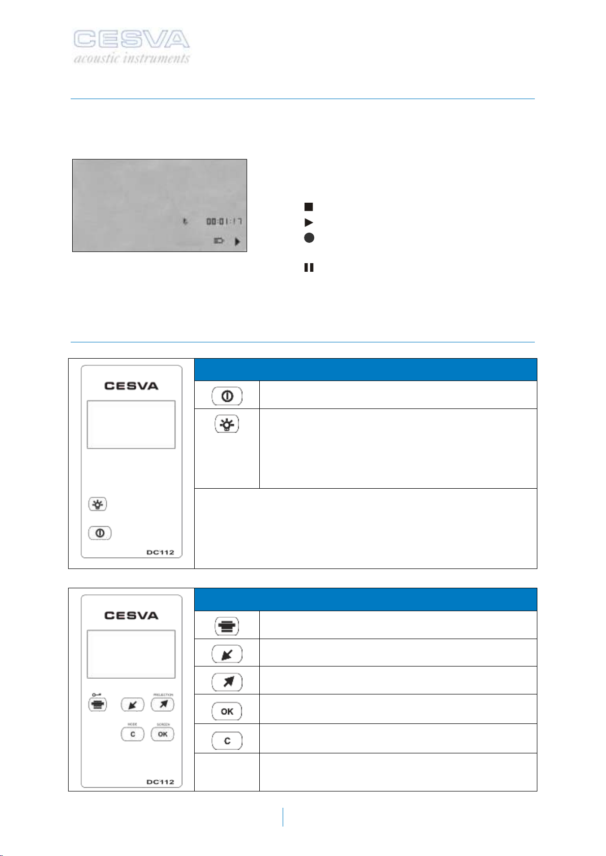
1.5 Screen
While the DC112k/DC112a is carrying out a measurement the following information is shown
in the bottom right-hand corner of the screen:
Measurement time lapsed t
Battery status indicator
Measurement status indicator:
omeasurement finished
omeasurement in progress
o(flashing) measurement with recording in
progress
omeasurement paused
1.6 Use of the keypad
GENERIC KEYS:
On/Off key of the DC112k/DC112a
On/Off key of the screen light. The light remains on for
five seconds, and then switches off automatically.
However, if the device is switched to the
DC112d/DC112 menu, the light will not switch off until
five seconds after exiting the menu.
MENU KEYS:
DC112k/DC112a menu access key
Key to move down the menu
Key to move up the menu
Key to validate or modify the selected option
Key to return to the previous menu or cancel
DC112k/DC112
User’s manual
9
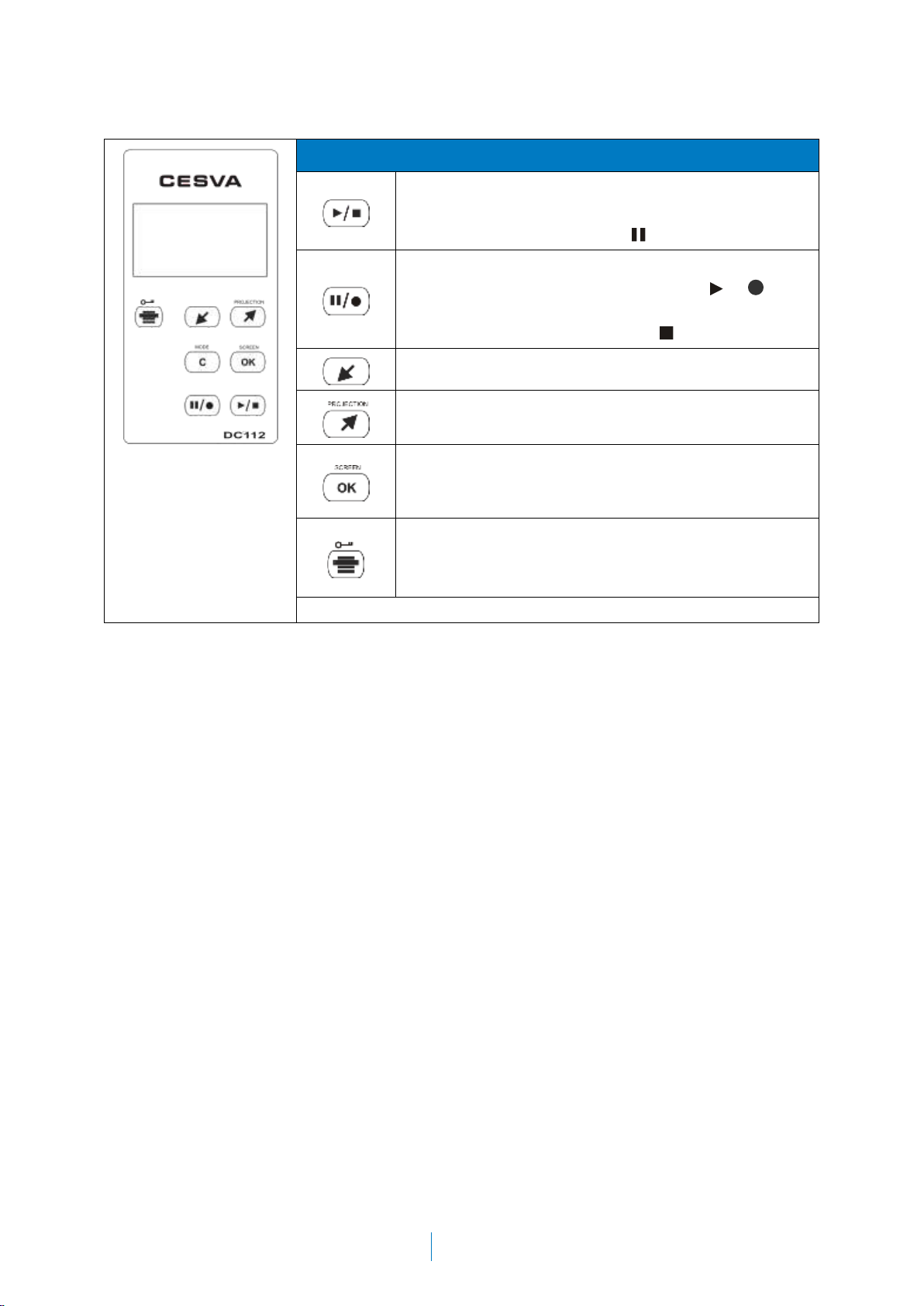
MEASUREMENT KEYS:
a) Key to begin or end a measurement
b) Key to continue a measurement (when the
DC112k/DC112a is on )
a) Key to interrupt (PAUSE) a measurement
(while the DC112k/DC112a is on or )
b) Or to begin a recording in the memory (when
the DC112k/DC112a is on )
Key to return to the previous octave band
Key to move on to the next octave band, or to move
on to the numerical screen with projected parameters.
Key to select the desired Dosimeter mode screen:
numerical screen, 1/1 spectrum analyser screen or
graphic screen
Key to block the keypad. To unblock it press this same
key + OK.
10
2. USING THE DC112k/DC112a
2.1 Initial steps
This chapter contains all the information necessary to configure, adjust and carry out
measurements with the DC112k/DC112a dosimeter.
2.1.1 Material and documentation
The first step is to check the material and documentation provided with the DC112k/DC112a:
Material included:
DC112k/DC112a dosimeter spectrum analyser
Case
One 6LF22 type 9 V alkaline battery
Connection cable for communication with the PC
Capture Studio Software
Documentation included:
User’s manual for the DC112k/DC112a dosimeter spectrum analyser
Guarantee
If any of these elements should be missing, contact your official distributor.
2.1.2 DC112k/DC112a Power source
The first operation to carry out, before switching on the DC112k/DC112a, is to supply power.
The DC112k/DC112a dosimeter is powered by a 6LF22 type 9V alkaline battery, or via the
USB port [8].
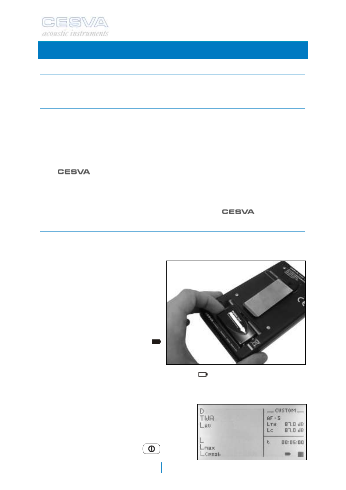
To fit the battery, remove the battery
protection cover [15] which can be found
at the back of the DC112k/DC112a. Insert
the battery and press until the contacts fit
perfectly (see figure).
The battery indicator symbol in the bottom
right hand corner of the dosimeter screen
shows the status of the battery (see
figure).
When the battery is fully charged the
symbol shows on the screen. As the
battery is discharged, the symbol empties.
When the battery is not sufficiently
charged for the DC112k/DC112a to work correctly the symbol will start to flash. Then, if
there is a measurement or recording in progress it will be paused, and the message
“BATTERY FLAT” will appear on the screen and the device will switch off. The battery must
be replaced.
To replace the batteries, the device must be switched
off. To remove the battery of the DC112k/DC112a,
open the battery compartment and pull upwards on
the back of the battery, as shown in the figure.
Once the batteries have been replaced, simply
switch on the device by pressing and press
2

DC112k/DC112
User’s manual
11
to continue the measurement.
The DC112k/DC112a can also be
powered via the USB port. To do this
connect the USB port of the
DC112k/DC112a [8] to a USB port of a
PC with the cable provided. When it is
connected the symbol will appear
where the battery symbol was.
RECOMMENDATIONS:
If the DC112k/DC112a is likely to be
unused for an extended period of time,
remove the batteries from the
DC112k/DC112a in order to prevent
damage caused by battery leakage.
We recommend that you always carry new replacement batteries
2.1.3 Connection and disconnection of the microphone
Before connecting or disconnecting the P007 microphone of the DC112k/DC112a
dosimeter, make sure the DC112k/DC112a is switched off.
To connect the microphone to the dosimeter, hold the male plug of the microphone [4] in
the middle. Insert it into the female socket [5] of the dosimeter, and press until it clicks.
To disconnect the microphone, hold the male plug
of the microphone in the middle [4]. Pull upwards on
the plug until disconnects.
IMPORTANT: Do not pull on the end of the plug by
the cable, as it will not disconnect. Similarly, do not
try to disconnect it by twisting the plug. In both
cases the device could be damaged.

12
2.1.4 Fixing the DC112k/DC112a on the user (worker)
The DC112k/DC112a has a support clip [13] to fix it to the user’s belt (see figure) and an
adjustable metal clip [2] to attach the microphone to their collar or helmet.
Any excess wire should be wound in a figure 8.
2.2 Beginning a measurement
2.2.1 Switching on the DC112k/DC112a
To switch on the DC112k/DC112a press:
A screen will appear, showing the logo, along with the DC112k/DC112a model.
After a few seconds the numerical screen of the DC112k/DC112a will appear (see 2.2.2).
If the DC112k/DC112a fails to come on, check that it is correctly connected to a power
source.
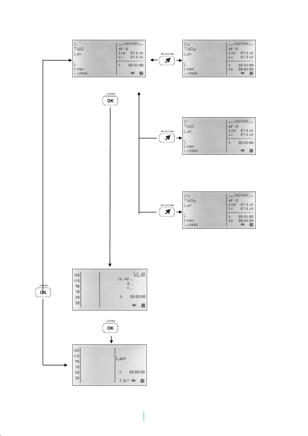
2.2.2 Display screen selection
Once the dosimeter has been switched on it shows the numerical screen.
To change from one measurement screen to another, simply press and the new
screen will appear.
The following are the screens of the DC112k/DC112a:
NUMERICAL SCREEN
The instrument has 4 types of numerical screen:
onumerical screen with LTH
oprojected parameters numerical screen
onumerical screen, parameters with LTH’ (only OSHA, MSHA and CUSTOM)
oprojected parameters numerical screen, with LTH’ (only OSHA, MSHA and CUSTOM)
1/1 SPECTRUM ANALYSER SCREEN (Only DC112a)
TIME HISTORY SCREEN
DC112k/DC112
User’s manual
13
Numerical screen with LTH
Projected parameters
numerical screen
Numerical screen with LTH’
(only OSHA, MSHA and
CUSTOM)
Projected parameters
numerical screen, with LTH’
(only OSHA, MSHA y
CUSTOM)
1/1 Spectrum analyser screen (only DC112a)
Time history screen
14
2.2.3 Testing the DC112k/DC112a
We recommend that you test the DC112k/DC112a before beginning a measurement,
adjust the sensitivity (if necessary), and test it again after the measurement has
finished.
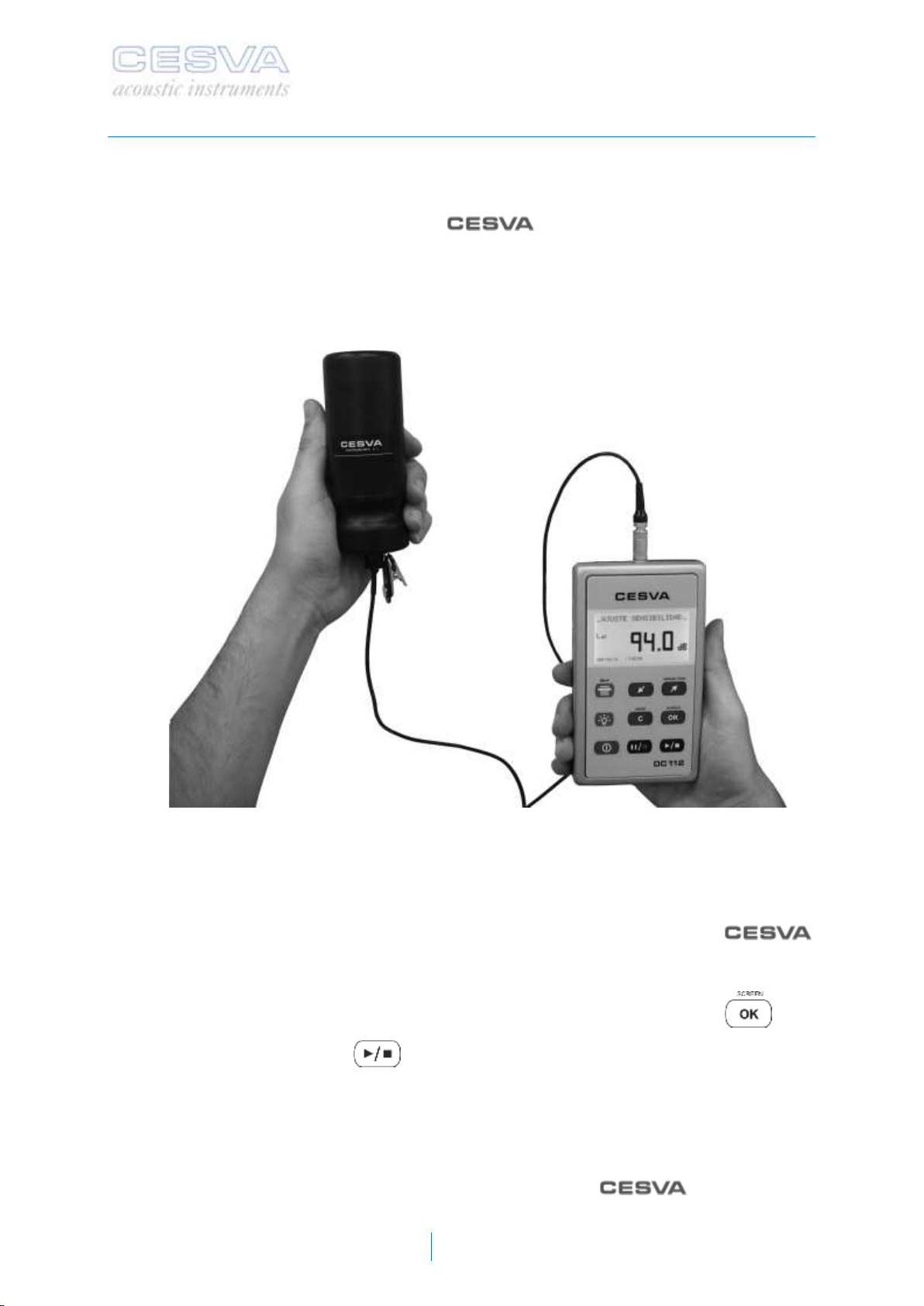
To test the DC112k/DC112a use the CB004 or CB006 sound calibrator
and proceed as follows:
1) Insert the microphone of the DC112k/DC112a in the cavity of the calibrator. Make
sure it has been fully inserted, and is parallel to the axis of the calibrator (see figure).
This may require a little force, as the microphone must fit into the calibrator perfectly.
Do not insert the DC112k/DC112a microphone roughly, as it may be damaged.
2) Switch on the calibrator and check the battery status. The indicator must be lit at all
times during the calibration process. The calibrator generates a tone of 94 dB at 1
kHz.
3) Apply the pressure to diffuse field corrections to the microphone at 1 kHz and the
corresponding ones to the influence of atmospheric pressure, temperature and
humidity in the calibrator. The diffuse field pressure correction of the
P007 microphone is 0.0 dB. That means the DC112k/DC112a should indicate a level
of 94.0 dB.
4) Switch the DC112k/DC112a to the numerical screen (2.2.2), by pressing:
5) Start the measurement:
6) Check that the value of the LAt function coincides with the value of 94.0 dB.
Should the value of the reading differ by more than 0.3 dB from the calculated value, the
sensitivity of the dosimeter will need to be adjusted. If not, the dosimeter is measuring
correctly, and the sensitivity does not need adjusting.
If the testing procedure is not satisfactory contact an official service, before
adjusting it.
DC112k/DC112
User’s manual
15
IMPORTANT: The sensitivity of the dosimeter must only be adjusted by authorised,
technically qualified personnel. Readjustment of the sensitivity entails the loss of traceability
in the calibration of the instrument.
To adjust the sensitivity, proceed as follows.
1) Press to end the measurement process.
2) Do not switch off the CB004 or CB006 calibrator, and keep it in the calibration
position.
3) Next press to access the menu of the DC112k/DC112a.
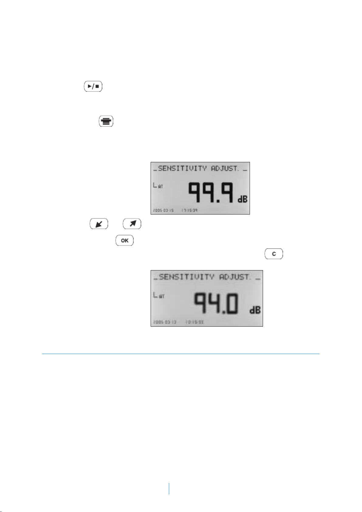
4) Access the option SETTINGS SENSITIVITY ADJUST.
5) The sound pressure level measured by the DC112k/DC112a will appear on the
screen, along with the time and date of the last time the sensitivity was modified.
6) Use the and keys to adjust the value calculated (94 dB + corrections)
7) Confirm with the key (the sensitivity will be modified, and the time and date will
be updated). If you do not want update the sensitivity then press to return to
the DC112k/DC112a menu.
.
2.3 Measuring with the DC112k/DC112a
The DC112k/DC112a measures the following parameters for the evaluation of noise at work:
the dose (D) with respect to a programmable criterion level (LC) and the time weighted
average (8hr) (TWA). In addition, the DC112K/DC112a allows these parameters to be
projected to the expected exposure time (tp) for measurements of shorter duration than the
exposure time. It measures the parameters with LTH’in the same way as for the OSHA,
MSHA and CUSTOM settings.
It also measures the average sound level (LAV) with A or C frequency weighting, fast or slow
time weighting, exchange rate [Q=3, 4, 5 or 6] and programmable threshold level (LTH, LTH’),
sound level (L) and its maximum (Lmax)] with A or C frequency weighting and fast or slow
time weighting and the peak level with C or Z weighting (LCpeak o LZpeak).
Only the DC112a simultaneously carries out a frequency analysis, measuring, in real time,
the equivalent continuous sound pressure levels for the octave bands between 63 Hz and 8
kHz with or without A frequency weighting, and the equivalent continuous sound pressure
level with A and C frequency weighting (LAT and LCT).

16
The time history analysis shows the evolution of the average sound pressure level with A or
C frequency weighting, fast or slow time weighting, exchange rate [Q=3, 4, 5 or 6] and
threshold level (LTH), for the programmable integration time (T).
2.3.1 Prior adjustments
Before beginning a measurement, the following parameters should be set:
SETUP: the dosimeter can be set by indicating which norm is to be followed for the
measurements, or alternatively the setting of each of the parameters can be personalised
according to the needs of the user.
Projection time (tp), predicted noise exposure time
Integration time (T). Average time used for the measurement of average sound pressure
level. The DC112k/DC112a saves the time history for the parameters (LCpeak or LZpeak, LAVT
and LAV’T). The DC112a also saves the time history of (LAT, LCT and LToct)
The frequency weighting applied to the spectrum measured.
To set these parameters select the SETTINGS MEASURING DOSIMETER option from
the DC112k/DC112a menu.
When the previous screen appears, select the parameter you want to configure SETUP, tpor
T using the and keys, then press . Use the key to cancel.
To modify the SETUP parameter, (two options):
1.- SELECTING THE NORM DIRECTLY
Select the norm using the and keys and press .
The norms and the predetermined parameters available are:
OSHA
MSHA
NIOSH
ACGIH
DoD
Frequency weighting
A
A
A
A
A
Time weighting
Slow
Slow
Slow
Slow
Slow
Q
5 dB
5 dB
3 dB
3 dB
3 dB
LTH
90 dBA
90 dBA
80 dBA
80 dBA
80 dBA
LTH’
80 dBA
80 dBA
-
-
-
Lc
90 dBA
90 dBA
85 dBA
85 dBA
85 dBA
Criterion time
8 h
8 h
8 h
8 h
8 h
Peak weighting
Z
-
-
Z
Z
When the required norm is selected, the dosimeter is automatically set with the appropriate
parameters.

DC112k/DC112
User’s manual
17
2.- PERSONALISED SETTING
Choose the CUSTOM option by pressing and and press .
A new screen will appear:
The parameters that appear on this screen can be set to the needs of the user.
These parameters are:
oCriterion level (LC): Level that would correspond to 100% of the DOSE if
measurement was carried out over 8 hours
oThreshold level (LTH): Level from which the values for the measurement of
LAV are taken
oExchange rate (Q): The exchange rate with which the average sound level
(LAV) is measured. The values available are: 3, 4, 5 and 6 dB.
oFrequency weighting (C/A): Frequency weighting with which the average
sound level (LAV), the sound level (L) and its maximum (Lmax) are measured.
The weightings available are A and C.
oTime weighting (F/S): Time weighting with which the average sound level
(LAV), the sound level (L) and its maximum (Lmax) are measured. The
weightings available are F and S.
oFrequency weighting (Lpeak): Frequency weighting with which the peak sound
pressure level is measured. The weightings available are C and Z.
To modify these parameters:
Select the parameter to be modified using and and press .
Next, choose the option or value required using and and press . Press
to cancel or return the DOSIMETER screen.
18
To modify the tpparameter, proceed as follows:
Set the hours value using and and press to confirm, repeat this
process to set the minutes value. The projection time tpis set from (HH:mm:00):
o0 to 99 for HH (Hours)
o0 to 59 for mm (minutes)
The minimum projection time is 1 minute.
To modify the T parameter, proceed as follows:
Select the numerical value using and and confirm by pressing . T
integration time may be set from
o1 to 59 seconds (1’’ – 59 ’’)
o1 to 59 minutes (1’ – 59’)
o1 to 99 hours (1H –99 H)
Finally select the time units: seconds (“), minutes (‘) or hours (H) with the help of
and and press to confirm. Use to cancel or return to the menu.
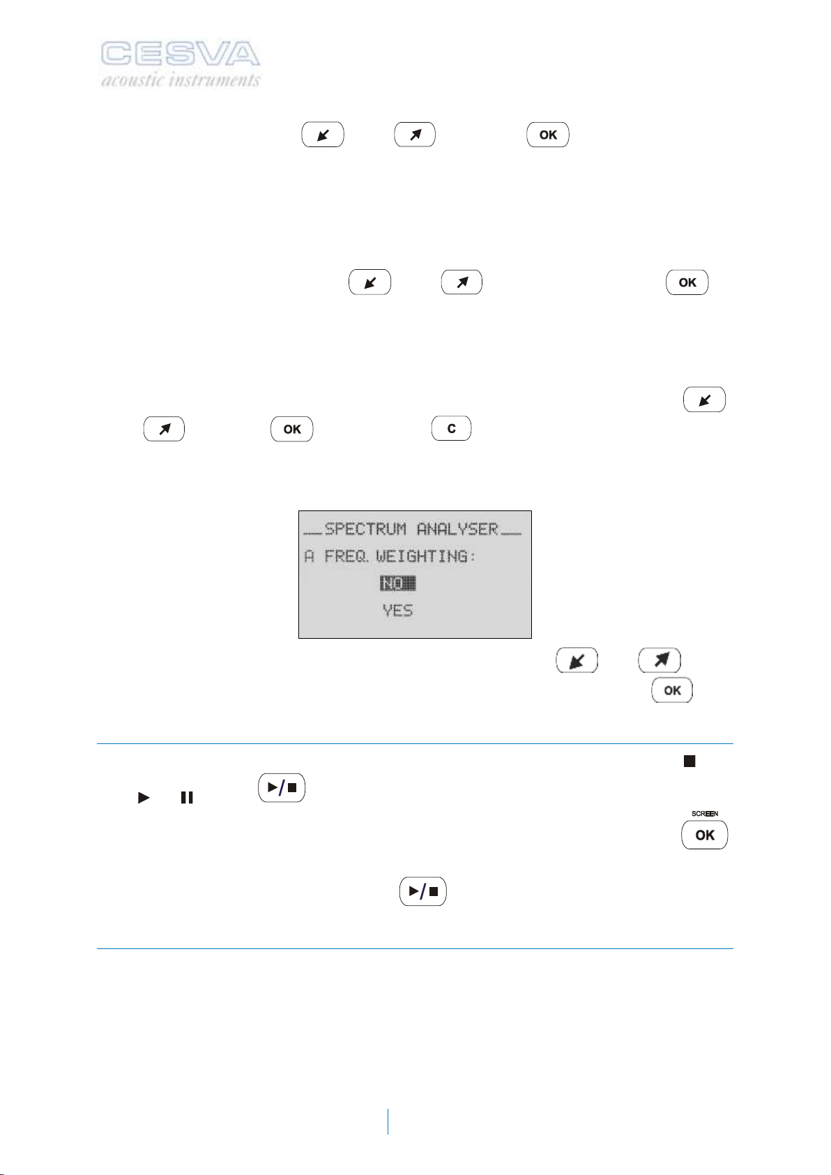
To set the frequency weighting applied to the spectrum access the menu of the DC112a and
select SETTINGS MEASURING SPECTRUM ANALYSER
When the above screen appears, select YES or NO using the and keys,
depending on whether you wish to apply A frequency weighting or not, and press .
2.3.2 Beginning a measurement
First of all, ensure that the sound level meter has no measuring process in progress ( ). If it
has ( or ), press to stop it. Next, choose the screen you want to display;
numerical (any of the types, see 2.2.2), spectrum analyser or time history, with the
key.
Once you have selected your screen, press to start the measurement process.
2.3.3 Function display
The DC112k/DC112a measures all functions simultaneously.
Described below are the different ways of displaying the acoustic functions for the
assessment of noise in the workplace while measurement is taking place. If you change the
kind of display (screen) or the octave band selected (spectrum analyser screen),
measurement will continue uninterrupted.
This manual suits for next models
1
Table of contents
Other CESVA Test Equipment manuals


