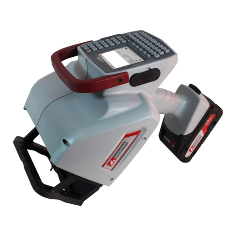
Ilsintech Keyman S1 User manual

Maintenance Manual
Maintenance ManualMaintenance Manual
Maintenance Manual
Optical fiber fusion splicer
Optical fiber fusion splicerOptical fiber fusion splicer
Optical fiber fusion splicer
Keyman S1
Keyman S1Keyman S1
Keyman S1
Please read through this manual completely
Please read through this manual completely Please read through this manual completely
Please read through this manual completely
before its first use.
before its first use.before its first use.
before its first use.

1
I .
I . I .
I . Safety guide
Safety guideSafety guide
Safety guide
II.
II. II.
II. Menu Control
Menu ControlMenu Control
Menu Control
1
11
1. Pop
. Pop. Pop
. Pop-
--
-up Menu
up Menu up Menu
up Menu Registration
RegistrationRegistration
Registration
2.
2. 2.
2. Setting Auto Heat
Setting Auto HeatSetting Auto Heat
Setting Auto Heat
3.
3. 3.
3. Setting Errors to be Affected or Ignored
Setting Errors to be Affected or IgnoredSetting Errors to be Affected or Ignored
Setting Errors to be Affected or Ignored
4.
4. 4.
4. Menu Clearing the Record of Total Number of Electric Discharge
Menu Clearing the Record of Total Number of Electric DischargeMenu Clearing the Record of Total Number of Electric Discharge
Menu Clearing the Record of Total Number of Electric Discharge
5.
5. 5.
5. Setting the Amount of Electric Discharge to be Cleared
Setting the Amount of Electric Discharge to be ClearedSetting the Amount of Electric Discharge to be Cleared
Setting the Amount of Electric Discharge to be Cleared
6.
6. 6.
6. Changing Maintenance Schedule
Changing Maintenance ScheduleChanging Maintenance Schedule
Changing Maintenance Schedule
III
IIIIII
III.
. .
. Corre
CorreCorre
Correction Menu
ction Menuction Menu
ction Menu
1.
1. 1.
1. Selecting Correction Menu
Selecting Correction MenuSelecting Correction Menu
Selecting Correction Menu
2.
2. 2.
2. LED Bright Menu
LED Bright MenuLED Bright Menu
LED Bright Menu
3. Uart Port
3. Uart Port3. Uart Port
3. Uart Port
4. ARC Settle
4. ARC Settle4. ARC Settle
4. ARC Settle
5
55
5.
. .
. Motor Setting
Motor SettingMotor Setting
Motor Setting
6
66
6.
. .
. Check Up
Check UpCheck Up
Check Up
7
77
7. Splice data Update
. Splice data Update. Splice data Update
. Splice data Update
IV.
IV. IV.
IV. Maintenance
MaintenanceMaintenance
Maintenance
1.
1. 1.
1. When an Error in Classifying SM and MM in Auto Mode Occurs
When an Error in Classifying SM and MM in Auto Mode OccursWhen an Error in Classifying SM and MM in Auto Mode Occurs
When an Error in Classifying SM and MM in Auto Mode Occurs
2.
2. 2.
2. Eccentricity of Positi
Eccentricity of PositiEccentricity of Positi
Eccentricity of Position of ARC Discharge
on of ARC Dischargeon of ARC Discharge
on of ARC Discharge
3.
3. 3.
3. Abnormal Arrangement of Optical Fibers in Connection Operation
Abnormal Arrangement of Optical Fibers in Connection OperationAbnormal Arrangement of Optical Fibers in Connection Operation
Abnormal Arrangement of Optical Fibers in Connection Operation
4.
4. 4.
4. Occurrence of a Length Difference When Optical Fibers are I
Occurrence of a Length Difference When Optical Fibers are IOccurrence of a Length Difference When Optical Fibers are I
Occurrence of a Length Difference When Optical Fibers are Initially
nitiallynitially
nitially Placed
Placed Placed
Placed
5.
5. 5.
5. Occurrence
OccurrenceOccurrence
Occurrence of an Error during Booting
of an Error during Booting of an Error during Booting
of an Error during Booting
6.
6. 6.
6. In case of High Connection Loss Rate
In case of High Connection Loss RateIn case of High Connection Loss Rate
In case of High Connection Loss Rate
7
77
7.
. .
. Rep
RepRep
Replacing the Battery
lacing the Batterylacing the Battery
lacing the Battery
8.
8. 8.
8. Replacing the Mirror
Replacing the MirrorReplacing the Mirror
Replacing the Mirror
9. Program Upgrade
9. Program Upgrade9. Program Upgrade
9. Program Upgrade
INDEX
INDEXINDEX
INDEX
2
22
2
This specification is applied to the maintenance and management
This specification is applied to the maintenance and management This specification is applied to the maintenance and management
This specification is applied to the maintenance and management
of
of of
of released
releasedreleased
released products of which versions are later than Keyman
products of which versions are later than Keyman products of which versions are later than Keyman
products of which versions are later than Keyman-
--
-S1
S1 S1
S1
Version 3.00.
Version 3.00. Version 3.00.
Version 3.00.
6
66
6
6
66
6
7
7 7
7
9
9 9
9
1
11
1
9
9 9
9
9
9 9
9
7
7 7
7
1
11
1
7
7 7
7
7
7 7
7
8
8 8
8

2
Keyman S1 has been designed and
Keyman S1 has been designed and Keyman S1 has been designed and
Keyman S1 has been designed and manufactured
manufacturedmanufactured
manufactured for convenient use in
for convenient use in for convenient use in
for convenient use in
indoor or outdoor working conditions. It is easy and simple to use, but
indoor or outdoor working conditions. It is easy and simple to use, but indoor or outdoor working conditions. It is easy and simple to use, but
indoor or outdoor working conditions. It is easy and simple to use, but
please read through this manual completely
please read through this manual completelyplease read through this manual completely
please read through this manual completely to avoid failures and safety
to avoid failures and safety to avoid failures and safety
to avoid failures and safety
accidents before you use it. Keyman S1 is designed to easily use, but also
accidents before you use it. Keyman S1 is designed to easily use, but also accidents before you use it. Keyman S1 is designed to easily use, but also
accidents before you use it. Keyman S1 is designed to easily use, but also
contains potential danger. Therefore, this manual contains all
contains potential danger. Therefore, this manual contains all contains potential danger. Therefore, this manual contains all
contains potential danger. Therefore, this manual contains all necessary
necessarynecessary
necessary
instructions to assure safe splice.
instructions to assure safe splice.instructions to assure safe splice.
instructions to assure safe splice.
Please keep this manual with the product all the time.
Please keep this manual with the product all the time. Please keep this manual with the product all the time.
Please keep this manual with the product all the time.
Ilsintech(Inc.) is not
Ilsintech(Inc.) is not Ilsintech(Inc.) is not
Ilsintech(Inc.) is not responsible
responsibleresponsible
responsible for
for for
for equipment
equipmentequipment
equipment damage and personal
damage and personal damage and personal
damage and personal
or physical damage caused by improper use or modification.
or physical damage caused by improper use or modification. or physical damage caused by improper use or modification.
or physical damage caused by improper use or modification.
If an abnormal condition such as the following occurs, immed
If an abnormal condition such as the following occurs, immedIf an abnormal condition such as the following occurs, immed
If an abnormal condition such as the following occurs, immediately turn
iately turn iately turn
iately turn
off power and disconnect the power source. Next, contact the
off power and disconnect the power source. Next, contact the off power and disconnect the power source. Next, contact the
off power and disconnect the power source. Next, contact the
maintenance service
maintenance service maintenance service
maintenance service personnel
personnelpersonnel
personnel in Ilsintech(Inc.).
in Ilsintech(Inc.). in Ilsintech(Inc.).
in Ilsintech(Inc.).
If unusual smoke, noise or odor or unusual overheating
If unusual smoke, noise or odor or unusual overheating If unusual smoke, noise or odor or unusual overheating
If unusual smoke, noise or odor or unusual overheating
occurs,
occurs,occurs,
occurs,
If foreign substance or liquid gets inside the splicer, or
If foreign substance or liquid gets inside the splicer, orIf foreign substance or liquid gets inside the splicer, or
If foreign substance or liquid gets inside the splicer, or
If
IfIf
If the splicer is dropped from a high place or suffers
the splicer is dropped from a high place or suffers the splicer is dropped from a high place or suffers
the splicer is dropped from a high place or suffers
damage
damagedamage
damage
Do not use
Do not use Do not use
Do not use AC
AC AC
AC power code other than the allowable power cord
power code other than the allowable power cord power code other than the allowable power cord
power code other than the allowable power cord
indicated. Doing so may cause a fire, electric shock or injury. Use the
indicated. Doing so may cause a fire, electric shock or injury. Use the indicated. Doing so may cause a fire, electric shock or injury. Use the
indicated. Doing so may cause a fire, electric shock or injury. Use the
power code provided with S1.
power code provided with S1. power code provided with S1.
power code provided with S1.
Do not touch the electrodes w
Do not touch the electrodes wDo not touch the electrodes w
Do not touch the electrodes when S1 is switched on.
hen S1 is switched on.hen S1 is switched on.
hen S1 is switched on.
High voltage and
High voltage and High voltage and
High voltage and
H
HH
Hi
ii
igh temperature from them may cause serious shock or a burn.
gh temperature from them may cause serious shock or a burn.gh temperature from them may cause serious shock or a burn.
gh temperature from them may cause serious shock or a burn.
Make sure that there is no dust or foreign substance inside the AC plug.
Make sure that there is no dust or foreign substance inside the AC plug. Make sure that there is no dust or foreign substance inside the AC plug.
Make sure that there is no dust or foreign substance inside the AC plug.
Ⅰ
ⅠⅠ
Ⅰ.
. .
. Safety guide
Safety guide Safety guide
Safety guide
Warning
WarningWarning
Warning

3
Then, Connect
Then, Connect Then, Connect
Then, Connect AC
AC AC
AC power cord to the specified charger and the outlet.
power cord to the specified charger and the outlet. power cord to the specified charger and the outlet.
power cord to the specified charger and the outlet.
Unsafe spl
Unsafe splUnsafe spl
Unsafe splice may cause smoke, fire, equipment
ice may cause smoke, fire, equipment ice may cause smoke, fire, equipment
ice may cause smoke, fire, equipment damage
damagedamage
damage, serious injury
, serious injury , serious injury
, serious injury
or death.
or death.or death.
or death.
Do not use a voltage other than the allowable power voltage indicated.
Do not use a voltage other than the allowable power voltage indicated.Do not use a voltage other than the allowable power voltage indicated.
Do not use a voltage other than the allowable power voltage indicated.
AC
AC AC
AC power supply for the specified charger is
power supply for the specified charger ispower supply for the specified charger is
power supply for the specified charger is AC 100
AC 100 AC 100
AC 100-
--
-240V,
240V,240V,
240V,
50
5050
50-
--
-60Hz
60Hz60Hz
60Hz.
..
.
Please check the AC power supply before us
Please check the AC power supply before usPlease check the AC power supply before us
Please check the AC power supply before using. AC power supply within
ing. AC power supply within ing. AC power supply within
ing. AC power supply within
the improper range may cause electric shock, equipment damage,
the improper range may cause electric shock, equipment damage, the improper range may cause electric shock, equipment damage,
the improper range may cause electric shock, equipment damage,
serious injury or even a death. Abnormally high AC output voltage or
serious injury or even a death. Abnormally high AC output voltage or serious injury or even a death. Abnormally high AC output voltage or
serious injury or even a death. Abnormally high AC output voltage or
frequency from the generator is a common problem.
frequency from the generator is a common problem. frequency from the generator is a common problem.
frequency from the generator is a common problem. M
MM
Measure AC output
easure AC output easure AC output
easure AC output
voltage with a circuit teste
voltage with a circuit testevoltage with a circuit teste
voltage with a circuit tester before connecting
r before connecting r before connecting
r before connecting AC
AC AC
AC power cord
power cordpower cord
power cord.
. .
. Regular
Regular Regular
Regular
inspection is needed because improper high voltage or frequency from
inspection is needed because improper high voltage or frequency from inspection is needed because improper high voltage or frequency from
inspection is needed because improper high voltage or frequency from
the generator may cause serious injury, electric shock, equipment
the generator may cause serious injury, electric shock, equipment the generator may cause serious injury, electric shock, equipment
the generator may cause serious injury, electric shock, equipment
damage
damagedamage
damage or death.
or death. or death.
or death.
Do not severely pull, heat or modify the provided AC power co
Do not severely pull, heat or modify the provided AC power coDo not severely pull, heat or modify the provided AC power co
Do not severely pull, heat or modify the provided AC power cord. The
rd. The rd. The
rd. The
use of damaged power cord may cause
use of damaged power cord may cause use of damaged power cord may cause
use of damaged power cord may cause hazardous
hazardoushazardous
hazardous conditions such as fire
conditions such as fire conditions such as fire
conditions such as fire
or injury.
or injury.or injury.
or injury.
Connect only to
Connect only to Connect only to
Connect only to 3
33
3-
--
-core AC
core AC core AC
core AC power cord. Do not connect to
power cord. Do not connect to power cord. Do not connect to
power cord. Do not connect to 2
22
2-
--
-core
core core
core power
power power
power
cord
cordcord
cord,
, ,
, c
cc
cable
ableable
able or plug.
or plug. or plug.
or plug.
To reduce the risk of electric shock, do not touch the AC plug, the AC
To reduce the risk of electric shock, do not touch the AC plug, the AC To reduce the risk of electric shock, do not touch the AC plug, the AC
To reduce the risk of electric shock, do not touch the AC plug, the AC
po
popo
power code and the splicer with wet hands.
wer code and the splicer with wet hands.wer code and the splicer with wet hands.
wer code and the splicer with wet hands.
Do not disassemble
Do not disassemble Do not disassemble
Do not disassemble AC
AC AC
AC adapter
adapteradapter
adapter,
, ,
, battery
batterybattery
battery
or the splicer. Any
or the splicer. Any or the splicer. Any
or the splicer. Any
modification to the splicer may cause a fire, electric shock or injury.
modification to the splicer may cause a fire, electric shock or injury.modification to the splicer may cause a fire, electric shock or injury.
modification to the splicer may cause a fire, electric shock or injury.
When you use external battery, see the following instructions.
When you use external battery, see the following instructions.When you use external battery, see the following instructions.
When you use external battery, see the following instructions.
The use of imp
The use of imp The use of imp
The use of improper
roper roper
roper
external battery may cause smoke,
external battery may cause smoke, external battery may cause smoke,
external battery may cause smoke,
equipment damage, or in serious cases burning, injury or death.
equipment damage, or in serious cases burning, injury or death.equipment damage, or in serious cases burning, injury or death.
equipment damage, or in serious cases burning, injury or death.
Do not throw the battery into a fire or a garbage dump
Do not throw the battery into a fire or a garbage dump Do not throw the battery into a fire or a garbage dump
Do not throw the battery into a fire or a garbage dump.
..
.
Do not charge the battery close to flames.
Do not charge the battery close to flames. Do not charge the battery close to flames.
Do not charge the battery close to flames.
Do not give severe vibration or shock to th
Do not give severe vibration or shock to th Do not give severe vibration or shock to th
Do not give severe vibration or shock to the battery.
e battery.e battery.
e battery.
If the battery is not fully charged within 6 hours or green
If the battery is not fully charged within 6 hours or green If the battery is not fully charged within 6 hours or green
If the battery is not fully charged within 6 hours or green
Warning
WarningWarning
Warning

4
LED lamp is not on, immediately stop charging and contact
LED lamp is not on, immediately stop charging and contact LED lamp is not on, immediately stop charging and contact
LED lamp is not on, immediately stop charging and contact
Ilsintech(Inc.)
Ilsintech(Inc.)Ilsintech(Inc.)
Ilsintech(Inc.)
Do not place any object on AC adapter during charging.
Do not place any object on AC adapter during charging.Do not place any object on AC adapter during charging.
Do not place any object on AC adapter during charging.
Only use the specified battery charger(S
Only use the specified battery charger(SOnly use the specified battery charger(S
Only use the specified battery charger(S-
--
-1B) and th
1B) and th1B) and th
1B) and the specified battery
e specified battery e specified battery
e specified battery
pack(S
pack(Spack(S
pack(S-
--
-1B). The use of any battery pack other than the specified one
1B). The use of any battery pack other than the specified one 1B). The use of any battery pack other than the specified one
1B). The use of any battery pack other than the specified one
may cause smoke or fire,
may cause smoke or fire, may cause smoke or fire,
may cause smoke or fire, equipment damage,
equipment damage, equipment damage,
equipment damage,
injury or death
injury or deathinjury or death
injury or death.
..
.
Only use the specified battery charger
Only use the specified battery chargerOnly use the specified battery charger
Only use the specified battery charger(
((
(S
SS
S-
--
-11
1111
11)
))
).
..
.
Do not use AC power other than the allowable power indi
Do not use AC power other than the allowable power indiDo not use AC power other than the allowable power indi
Do not use AC power other than the allowable power indicated.
cated.cated.
cated.
Do not let battery
Do not let batteryDo not let battery
Do not let battery(
((
(S
SS
S-
--
-1B
1B1B
1B)
))
) or the terminal of the specified charger be
or the terminal of the specified charger be or the terminal of the specified charger be
or the terminal of the specified charger be
short
shortshort
short-
--
-circuited.
circuited.circuited.
circuited.
Excessive current flow may cause damage to the
Excessive current flow may cause damage to the Excessive current flow may cause damage to the
Excessive current flow may cause damage to the
equipment and persons.
equipment and persons.equipment and persons.
equipment and persons.
Avoid the use of S1 in a hazardous location in which harmful gas or
Avoid the use of S1 in a hazardous location in which harmful gas or Avoid the use of S1 in a hazardous location in which harmful gas or
Avoid the use of S1 in a hazardous location in which harmful gas or
flammable gas can gen
flammable gas can genflammable gas can gen
flammable gas can generate.
erate.erate.
erate.
In such conditions, the electrical arc of the
In such conditions, the electrical arc of the In such conditions, the electrical arc of the
In such conditions, the electrical arc of the
fusion splicer can result in bursting or fire.
fusion splicer can result in bursting or fire.fusion splicer can result in bursting or fire.
fusion splicer can result in bursting or fire.
Do not use compressed gas to clean S1.
Do not use compressed gas to clean S1.Do not use compressed gas to clean S1.
Do not use compressed gas to clean S1.
If you carry the transport case connected with a belt,
If you carry the transport case connected with a belt,If you carry the transport case connected with a belt,
If you carry the transport case connected with a belt,
first check the belt
first check the belt first check the belt
first check the belt
is strong enough.
is strong enough. is strong enough.
is strong enough. T
TT
The worn belt may f
he worn belt may fhe worn belt may f
he worn belt may fail to sustain the case, resulting in
ail to sustain the case, resulting in ail to sustain the case, resulting in
ail to sustain the case, resulting in
equipment loss or injury.
equipment loss or injury.equipment loss or injury.
equipment loss or injury.
Wear safety glasses for protection from glass fibers. Glass fibers may
Wear safety glasses for protection from glass fibers. Glass fibers may Wear safety glasses for protection from glass fibers. Glass fibers may
Wear safety glasses for protection from glass fibers. Glass fibers may
cause serious damage to eyes or skin tissue.
cause serious damage to eyes or skin tissue.cause serious damage to eyes or skin tissue.
cause serious damage to eyes or skin tissue.
Do not use the splicer in high
Do not use the splicer in high Do not use the splicer in high
Do not use the splicer in high temperature
temperaturetemperature
temperature conditions. Doing so may
conditions. Doing so may conditions. Doing so may
conditions. Doing so may
cause
cause cause
cause equipment loss or injury.
equipment loss or injury.equipment loss or injury.
equipment loss or injury.
Do not use a splicer in high
Do not use a splicer in high Do not use a splicer in high
Do not use a splicer in high temperature
temperaturetemperature
temperature conditions. Doing so may cause
conditions. Doing so may cause conditions. Doing so may cause
conditions. Doing so may cause
equipment loss or injury.
equipment loss or injury.equipment loss or injury.
equipment loss or injury.
Warning
WarningWarning
Warning

5
D
DD
During or after heating protection sleeves in the tube heater, do not
uring or after heating protection sleeves in the tube heater, do not uring or after heating protection sleeves in the tube heater, do not
uring or after heating protection sleeves in the tube heater, do not
touch both parts. Injury from high temperature
touch both parts. Injury from high temperature touch both parts. Injury from high temperature
touch both parts. Injury from high temperature could occur.
could occur.could occur.
could occur.
Do not place
Do not placeDo not place
Do not place
S1 in unstable locations.
S1 in unstable locations.S1 in unstable locations.
S1 in unstable locations.
If the equipment is dropped, injury
If the equipment is dropped, injury If the equipment is dropped, injury
If the equipment is dropped, injury
or equipment damage could occur.
or equipment damage could occur.or equipment damage could occur.
or equipment damage could occur.
S1 is a precision instrument. It should be handled with care and precision.
S1 is a precision instrument. It should be handled with care and precision. S1 is a precision instrument. It should be handled with care and precision.
S1 is a precision instrument. It should be handled with care and precision.
When transporting it, use its specified transport case
When transporting it, use its specified transport case When transporting it, use its specified transport case
When transporting it, use its specified transport case to protect it from
to protect it from to protect it from
to protect it from
dust, dust, moisture, shock and impact.
dust, dust, moisture, shock and impact.dust, dust, moisture, shock and impact.
dust, dust, moisture, shock and impact.
Replace the electrodes the right way.
Replace the electrodes the right way.Replace the electrodes the right way.
Replace the electrodes the right way.
Only use
Only useOnly use
Only use
the specified
the specified the specified
the specified electrode
electrodeelectrode
electrodes.
s.s.
s.
Place the new electrode in the right position.
Place the new electrode in the right position.Place the new electrode in the right position.
Place the new electrode in the right position.
Replace the electrodes in pairs.
Replace the electrodes in pairs.Replace the electrodes in pairs.
Replace the electrodes in pairs.
Not doing so may cause abnorma
Not doing so may cause abnormaNot doing so may cause abnorma
Not doing so may cause abnormal arc and equipment damage or
l arc and equipment damage or l arc and equipment damage or
l arc and equipment damage or
deterioration in
deterioration in deterioration in
deterioration in splice
splicesplice
splice performance.
performance. performance.
performance.
Only use ethyl alcohol (more than 96 %) to clean the splicer including
Only use ethyl alcohol (more than 96 %) to clean the splicer including Only use ethyl alcohol (more than 96 %) to clean the splicer including
Only use ethyl alcohol (more than 96 %) to clean the splicer including
object lenses
object lensesobject lenses
object lenses, V
, V, V
, V-
--
-groove
groovegroove
grooves
ss
s,
, ,
, wind
windwind
wind-
--
-proof glass
proof glassproof glass
proof glass, LCD
, LCD , LCD
, LCD monitor
monitormonitor
monitor,
, ,
, and the main
and the main and the main
and the main
body.
body.body.
body.
To prevent modification, discoloration an
To prevent modification, discoloration anTo prevent modification, discoloration an
To prevent modification, discoloration and low performance, do not use
d low performance, do not use d low performance, do not use
d low performance, do not use
any kind of chemicals
any kind of chemicalsany kind of chemicals
any kind of chemicals.
..
.
Do not use lubricants including oil and grease for S1. Doing so may
Do not use lubricants including oil and grease for S1. Doing so may Do not use lubricants including oil and grease for S1. Doing so may
Do not use lubricants including oil and grease for S1. Doing so may
cause performance deterioration and equipment damage.
cause performance deterioration and equipment damage.cause performance deterioration and equipment damage.
cause performance deterioration and equipment damage.
Do not store the equipment in high
Do not store the equipment in highDo not store the equipment in high
Do not store the equipment in high-
--
-temperature or high
temperature or hightemperature or high
temperature or high-
--
-humidity
humidity humidity
humidity
Caution
CautionCaution
Caution

6
⇒
⇒⇒
⇒
To activate a mode, select the mode by
To activate a mode, select the mode by To activate a mode, select the mode by
To activate a mode, select the mode by
moving the cursor and then push
moving the cursor and then push moving the cursor and then push
moving the cursor and then push
key.
key. key.
key.
P
PP
Pu
uu
ush E
sh Esh E
sh Es
ss
sc to return to previous menu.
c to return to previous menu.c to return to previous menu.
c to return to previous menu.
conditions.
conditions.conditions.
conditions.
E
EE
Equipment damage could occur.
quipment damage could occur.quipment damage could occur.
quipment damage could occur.
Q
QQ
Qualified experts should check up
ualified experts should check up ualified experts should check up
ualified experts should check up technical
technicaltechnical
technical matters concerning S1. Not
matters concerning S1. Not matters concerning S1. Not

matters concerning S1. Not
doing so may cause fire or electric shock. Please contact qualified
doing so may cause fire or electric shock. Please contact qualified doing so may cause fire or electric shock. Please contact qualified
doing so may cause fire or electric shock. Please contact qualified
service personnel in Ilsintech(Inc.) and get A/S service.
service personnel in Ilsintech(Inc.) and get A/S service.service personnel in Ilsintech(Inc.) and get A/S service.
service personnel in Ilsintech(Inc.) and get A/S service.
1.
1. 1.
1. Pop
PopPop
Pop-
--
-up Menu Regis
up Menu Regisup Menu Regis
up Menu Registration
trationtration
tration
Both Connection M
Both Connection MBoth Connection M
Both Connection Mo
oo
ode and Heater Mode can be registered in Pop
de and Heater Mode can be registered in Popde and Heater Mode can be registered in Pop
de and Heater Mode can be registered in Pop-
--
-up
up up
up
menu, which allows user to select each mode in a quick manner by pushing
menu, which allows user to select each mode in a quick manner by pushing menu, which allows user to select each mode in a quick manner by pushing
menu, which allows user to select each mode in a quick manner by pushing
either up or down direction key.
either up or down direction key. either up or down direction key.
either up or down direction key.
Push
PushPush
Push
or
or or
or
Registe
RegisteRegiste
Registering each mode
ring each modering each mode
ring each mode
Connection M
Connection M Connection M
Connection Mo
oo
ode R
de Rde R
de Re
ee
egistration
gistration gistration
gistration
Push Menu Key
Push Menu KeyPush Menu Key
Push Menu Key
→
→→
→ Select Connection M
Select Connection M Select Connection M
Select Connection Mo
oo
ode
de de
de →
→→
→ Move to the mode to
Move to the mode to Move to the mode to
Move to the mode to
be
be be
be
registered
registered registered
registered →
→→
→ Push Set Key
Push Set Key Push Set Key
Push Set Key →
→→
→
Pop
PopPop
Pop-
--
-up menu registration box appears
up menu registration box appears up menu registration box appears
up menu registration box appears
→
→→
→ Assign a number to be used by moving up and down direction key
Assign a number to be used by moving up and down direction key Assign a number to be used by moving up and down direction key
Assign a number to be used by moving up and down direction keys
s s
s
→
→→
→ Push
Push Push
Push →
→→
→ Completion of the registration
Completion of the registration Completion of the registration
Completion of the registration
Heater M
Heater MHeater M
Heater Mo
oo
ode R
de Rde R
de Re
ee
egistration
gistration gistration
gistration
Ⅱ
ⅡⅡ
Ⅱ.
..
.
Menu Control
Menu ControlMenu Control
Menu Control
1
11
1
2
22
2

7
Push Menu Key
Push Menu KeyPush Menu Key
Push Menu Key
→
→→
→
Select Heater M
Select Heater MSelect Heater M
Select Heater Mo
oo
ode
de de
de →
→→
→ Move to the mode to be
Move to the mode to be Move to the mode to be
Move to the mode to be
registered
registered registered
registered →
→→
→ Push Set Key
Push Set Key Push Set Key
Push Set Key →
→→
→
Pop
PopPop
Pop-
--
-up menu registration box appears
up menu registration box appears up menu registration box appears
up menu registration box appears
→
→→
→ Assign a number to be used by moving up and down directi
Assign a number to be used by moving up and down directi Assign a number to be used by moving up and down directi
Assign a number to be used by moving up and down direction keys
on keys on keys
on keys
→
→→
→ Push
Push Push
Push →
→→
→ Completion of the registration
Completion of the registration Completion of the registration
Completion of the registration
2
22
2.
. .
. Setting Auto
Setting Auto Setting Auto
Setting Auto Heat
HeatHeat
Heat
The function of setting
The function of setting The function of setting
The function of setting auto heat is useful,
auto heat is useful, auto heat is useful,
auto heat is useful,
especially, in performing consecutive connection works. When the wind
especially, in performing consecutive connection works. When the wind especially, in performing consecutive connection works. When the wind
especially, in performing consecutive connection works. When the wind
protection cover is opened after completing a connection, the
protection cover is opened after completing a connection, the protection cover is opened after completing a connection, the
protection cover is opened after completing a connection, the heater starts
heater starts heater starts
heater starts
to be operating and stops at the end of pre
to be operating and stops at the end of preto be operating and stops at the end of pre
to be operating and stops at the end of pre-
--
-set time period.
set time period. set time period.
set time period.
Menu Key
Menu Key Menu Key
Menu Key →
→→
→ Main Menu
Main Menu Main Menu
Main Menu →
→→
→ Select
Select Select
Select additional
additionaladditional
additional function of connection
function of connection function of connection
function of connection →
→→
→
Select basic
Select basic Select basic
Select basic →
→→
→ Set to On or Off in Auto heat
Set to On or Off in Auto heat Set to On or Off in Auto heat
Set to On or Off in Auto heat
3
33
3.
. .
. Setting Errors to be Affected or Ignored
Setting Errors to be Affected or IgnoredSetting Errors to be Affected or Ignored
Setting Errors to be Affected or Ignored
Errors not affecting
Errors not affectingErrors not affecting
Errors not affecting the operative function of connection can be either
the operative function of connection can be either the operative function of connection can be either
the operative function of connection can be either
ignored or selected.
ignored or selected. ignored or selected.
ignored or selected.
Menu Key
Menu Key Menu Key
Menu Key →
→→
→ Main Menu
Main Menu Main Menu
Main Menu →
→→
→ Select additional function of connection
Select additional function of connection Select additional function of connection
Select additional function of connection →
→→
→
Ignore connection errors
Ignore connection errors Ignore connection errors
Ignore connection errors →
→→
→ Set On or Off for each item
Set On or Off for each item Set On or Off for each item
Set On or Off for each item
4
44
4.
. .
. Menu Clearing the Record of Total Number of Electric
Menu Clearing the Record of Total Number of Electric Menu Clearing the Record of Total Number of Electric
Menu Clearing the Record of Total Number of Electric
Di
DiDi
Discharge
schargescharge
scharge
The total number of electric discharge can be
The total number of electric discharge can be The total number of electric discharge can be
The total number of electric discharge can be
initialized.
initialized.initialized.
initialized.
Menu Key
Menu Key Menu Key
Menu Key →
→→
→ Aux
Aux Aux
Aux →
→→
→ Select CLEAR ARC
Select CLEAR ARC Select CLEAR ARC
Select CLEAR ARC
COUNT, in which push, simultaneously, both X,
COUNT, in which push, simultaneously, both X, COUNT, in which push, simultaneously, both X,
COUNT, in which push, simultaneously, both X,
Y Key and
Y Key and Y Key and
Y Key and Key.
Key.Key.
Key.
T
TT
The total number of electric discharge becomes
he total number of electric discharge becomes he total number of electric discharge becomes
he total number of electric discharge becomes

8
0 when selecting
0 when selecting 0 when selecting
0 when selecting Initialize
InitializeInitialize
Initialize and pushing Enter key.
and pushing Enter key. and pushing Enter key.
and pushing Enter key.
5
55
5.
..
. Setting the Amount of Electric Discharge to be Cleared
Setting the Amount of Electric Discharge to be Cleared Setting the Amount of Electric Discharge to be Cleared
Setting the Amount of Electric Discharge to be Cleared
The electric
The electric The electric
The electric discharge
dischargedischarge
discharge amount to be cleared
amount to be cleared amount to be cleared
amount to be cleared can
can can
can
be
bebe
be
set.
set. set.
set.
Menu Key
Menu Key Menu Key
Menu Key →
→→
→ Main
Main Main
Main→
→→
→ Select Splice Option, in
Select Splice Option, in Select Splice Option, in
Select Splice Option, in
which push, simultaneously, both keys of X, Y
which push, simultaneously, both keys of X, Y which push, simultaneously, both keys of X, Y
which push, simultaneously, both keys of X, Y
and
and and
and
.
The amount of electric
The amount of electricThe amount of electric
The amount of electric discharge to be cleared
discharge to be cleared discharge to be cleared
discharge to be cleared
can
can can
can
be re
be rebe re
be re-
--
-set.
set.set.
set.
6
66
6.
. .
. Changing Maintenance Schedule.
Changing Maintenance Schedule. Changing Maintenance Schedule.
Changing Maintenance Schedule.
Menu Key
Menu Key Menu Key
Menu Key →
→→
→ Other
Other Other
Other→
→→
→ Select Maintenance, in
Select Maintenance, in Select Maintenance, in
Select Maintenance, in
which push, simultaneously, both X, Y Key and
which push, simultaneously, both X, Y Key and which push, simultaneously, both X, Y Key and
which push, simultaneously, both X, Y Key and
Key. Change the date.
Key. Change the date. Key. Change the date.
Key. Change the date.

9
1.
1. 1.
1. Selecting Correction Menu
Selecting Correction MenuSelecting Correction Menu
Selecting Correction Menu
Push Menu Key
Push Menu Key Push Menu Key
Push Menu Key →
→→
→ SUB
SUB SUB
SUB →
→→
→ OTHER
OTHER OTHER
OTHER →
→→
→ Select
Select Select
Select
System Setting
System Setting System Setting
System Setting →
→→
→ in which screen, push,
in which screen, push, in which screen, push,
in which screen, push,
simultaneously, both X, Y Key and
simultaneously, both X, Y Key and simultaneously, both X, Y Key and
simultaneously, both X, Y Key and Key.
Key.Key.
Key.
2
22
2.
. .
. 2. LED Bright Menu
2. LED Bright Menu2. LED Bright Menu
2. LED Bright Menu
This menu is used for adjusting the brightness of camera flashes.
This menu is used for adjusting the brightness of camera flashes. This menu is used for adjusting the brightness of camera flashes.
This menu is used for adjusting the brightness of camera flashes. A
AA
A sub
sub sub
sub
menu appears when selecting this menu.
menu appears when selecting this menu. menu appears when selecting this menu.
menu appears when selecting this menu.
LED Bright
LED BrightLED Bright
LED Bright
After adjusting the brightness of flashes by selecting
After adjusting the brightness of flashes by selecting After adjusting the brightness of flashes by selecting
After adjusting the brightness of flashes by selecting
the menu for adjusting the brightness of camera
the menu for adjusting the brightness of camera the menu for adjusting the brightness of camera
the menu for adjusting the brightness of camera
flashes, select
flashes, select flashes, select
flashes, select Menu Key
Menu Key Menu Key
Menu Key →
→→
→ OTHER
OTHER OTHER
OTHER →
→→
→ LED CHECK,
LED CHECK, LED CHECK,
LED CHECK,
in which keep the brightness value between 80~86.
in which keep the brightness value between 80~86.in which keep the brightness value between 80~86.
in which keep the brightness value between 80~86.
LED Bright (Auto)
LED Bright (Auto)LED Bright (Auto)
LED Bright (Auto)
This is an automatically adjusted brightness value of
This is an automatically adjusted brightness value of This is an automatically adjusted brightness value of
This is an automatically adjusted brightness value of
LED flashes which is applied when the device is
LED flashes which is applied when the device is LED flashes which is applied when the device is
LED flashes which is applied when the device is
booted. The standard value has been set to 83.
booted. The standard value has been set to 83. booted. The standard value has been set to 83.
booted. The standard value has been set to 83.
Ⅲ
ⅢⅢ
Ⅲ.
..
.
Correction Menu
Correction MenuCorrection Menu
Correction Menu

10
2
22
2.
. .
. 3. Uart Port
3. Uart Port3. Uart Port
3. Uart Port
Check if it has been set to Data Download when performing Program Up
Check if it has been set to Data Download when performing Program UpCheck if it has been set to Data Download when performing Program Up
Check if it has been set to Data Download when performing Program Up-
--
-
Grade.
Grade. Grade.
Grade.
2
22
2.
. .
. 4. ARC Settle
4. ARC Settle4. ARC Settle
4. ARC Settle
ARC Position
ARC PositionARC Position
ARC Position
Menu used for correcting the centers of arranged
Menu used for correcting the centers of arranged Menu used for correcting the centers of arranged
Menu used for correcting the centers of arranged
optical fibers and ARC
optical fibers and ARCoptical fibers and ARC
optical fibers and ARC
Limittion Re
Limittion ReLimittion Re
Limittion Re-
--
-arc times
arc timesarc times
arc times
Menu for sett
Menu for settMenu for sett
Menu for setting re
ing reing re
ing re-
--
-arc discharge times
arc discharge timesarc discharge times
arc discharge times
The number set is the maximum times allowing re
The number set is the maximum times allowing reThe number set is the maximum times allowing re
The number set is the maximum times allowing re-
--
-
arc discharge.
arc discharge. arc discharge.
arc discharge.

11
2
22
2.
. .
. 5. Motor Setting
5. Motor Setting5. Motor Setting
5. Motor Setting
Menu for setting measuring values of camera
Menu for setting measuring values of camera Menu for setting measuring values of camera
Menu for setting measuring values of camera
motor and X, Y motor
motor and X, Y motor motor and X, Y motor
motor and X, Y motor
T
TT
The initial setting value of each motor shall be
he initial setting value of each motor shall be he initial setting value of each motor shall be
he initial setting value of each motor shall be
recorded pri
recorded prirecorded pri
recorded prior to Up
or to Upor to Up
or to Up-
--
-Grade.
Grade. Grade.
Grade.
A screen as next figure appears upon selecting
A screen as next figure appears upon selecting A screen as next figure appears upon selecting
A screen as next figure appears upon selecting
the menu.
the menu. the menu.
the menu.
Core Equalization
Core EqualizationCore Equalization
Core Equalization
Menu for correcting images from the camera
Menu for correcting images from the cameraMenu for correcting images from the camera
Menu for correcting images from the camera
Auto Mode: Menu for setting the reference position of the camera in
Auto Mode: Menu for setting the reference position of the camera in Auto Mode: Menu for setting the reference position of the camera in
Auto Mode: Menu for setting the reference position of the camera in
Auto M
Auto MAuto M
Auto Mo
oo
ode
dede
de
(Do not change the initially set value
(Do not change the initially set value (Do not change the initially set value
(Do not change the initially set value)
))
)
Except Auto: Menu for correcting the size of optic fibers
Except Auto: Menu for correcting the size of optic fibersExcept Auto: Menu for correcting the size of optic fibers
Except Auto: Menu for correcting the size of optic fibers’
’’
’ core when
core when core when
core when
conducting ALIGNMENT
conducting ALIGNMENT conducting ALIGNMENT
conducting ALIGNMENT
(Do not change the initially set value)
(Do not change the initially set value)(Do not change the initially set value)
(Do not change the initially set value)
Loss Calculation equalize: The control value of camera, which is to be
Loss Calculation equalize: The control value of camera, which is to be Loss Calculation equalize: The control value of camera, which is to be
Loss Calculation equalize: The control value of camera, which is to be
applied in calculating Loss
applied in calculating Loss applied in calculating Loss
applied in calculating Loss
(Do not change the init
(Do not change the init(Do not change the init
(Do not change the initially set value)
ially set value)ially set value)
ially set value)
Fiber Type Menu
Fiber Type MenuFiber Type Menu
Fiber Type Menu
Menu for correcting image data of optical fibers in Auto Mode
Menu for correcting image data of optical fibers in Auto Mode Menu for correcting image data of optical fibers in Auto Mode
Menu for correcting image data of optical fibers in Auto Mode
Fiber Type Resister: Menu for setting a standard value for recognizing
Fiber Type Resister: Menu for setting a standard value for recognizing Fiber Type Resister: Menu for setting a standard value for recognizing
Fiber Type Resister: Menu for setting a standard value for recognizing
Fibers in Auto Mode
Fibers in Auto Mode Fibers in Auto Mode
Fibers in Auto Mode
(Do not change the initially set value).
(Do not change the initially set value).(Do not change the initially set value).
(Do not change the initially set value).
T
TT
The value is
he value is he value is
he value is
automatica
automaticaautomatica
automatically adjusted when correcting the motor.
lly adjusted when correcting the motor. lly adjusted when correcting the motor.
lly adjusted when correcting the motor.
Fiber Type Limit: Menu for setting a threshold value for recognizing
Fiber Type Limit: Menu for setting a threshold value for recognizing Fiber Type Limit: Menu for setting a threshold value for recognizing
Fiber Type Limit: Menu for setting a threshold value for recognizing
Fibers in Auto mode
Fibers in Auto mode Fibers in Auto mode
Fibers in Auto mode
(Do not change the initially set value).
(Do not change the initially set value).(Do not change the initially set value).
(Do not change the initially set value).
Fiber Total Limit:
Fiber Total Limit: Fiber Total Limit:
Fiber Total Limit: Menu for setting a threshold value of Fiber data
Menu for setting a threshold value of Fiber data Menu for setting a threshold value of Fiber data
Menu for setting a threshold value of Fiber data
(Do
(Do (Do
(Do
not change
not change not change
not change the initially set value).
the initially set value).the initially set value).
the initially set value).
1
11
1
2
22
2
1
11
1
2
22
2
3
33
3
3
33
3

12
First
FirstFirst
First-
--
-Time Compensation:
Time Compensation: Time Compensation:
Time Compensation: Menu for setting an automatic
Menu for setting an automatic Menu for setting an automatic
Menu for setting an automatic correction
correctioncorrection
correction
value in Auto Mode
value in Auto Mode value in Auto Mode
value in Auto Mode
(Do not change the initially set value).
(Do not change the initially set value).(Do not change the initially set value).
(Do not change the initially set value).
Temp Compensation
Temp CompensationTemp Compensation
Temp Compensation
Menu for setting temperature compensation
Menu for setting temperature compensation Menu for setting temperature compensation
Menu for setting temperature compensation
(Do not change the initially set value).
(Do not change the initially set value).(Do not change the initially set value).
(Do not change the initially set value).
X, Y Motor Offset
X, Y Motor OffsetX, Y Motor Offset
X, Y Motor Offset
Menu for setting a compensation value when a length difference occurs upon
Menu for setting a compensation value when a length difference occurs upon Menu for setting a compensation value when a length difference occurs upon
Menu for setting a compensation value when a length difference occurs upon
placing right and left fibers
placing right and left fibers placing right and left fibers
placing right and left fibers
2
22
2.
. .
. 6. Check Up
6. Check Up6. Check Up
6. Check Up
Motor Setting: A screen which shows the reference line when adjusting
Motor Setting: A screen which shows the reference line when adjusting Motor Setting: A screen which shows the reference line when adjusting
Motor Setting: A screen which shows the reference line when adjusting
the position of optical fibers (, which
the position of optical fibers (, whichthe position of optical fibers (, which
the position of optical fibers (, which are used in replacing a
are used in replacing a are used in replacing a
are used in replacing a lens
lenslens
lens or
or or
or
camera)
camera)camera)
camera)
Fiber Shape Set 1: A standard value used for judging the faulty status of
Fiber Shape Set 1: A standard value used for judging the faulty status of Fiber Shape Set 1: A standard value used for judging the faulty status of
Fiber Shape Set 1: A standard value used for judging the faulty status of
a cut section of optical fibers (Clad Section).
a cut section of optical fibers (Clad Section). a cut section of optical fibers (Clad Section).
a cut section of optical fibers (Clad Section). T
TT
The bigger the size of this
he bigger the size of this he bigger the size of this
he bigger the size of this
value is, the less sensitive the fault detection capability beco
value is, the less sensitive the fault detection capability becovalue is, the less sensitive the fault detection capability beco
value is, the less sensitive the fault detection capability becomes.
mes. mes.
mes.
1Fiber Shape Set 2: A standard value used for judging the faulty status
1Fiber Shape Set 2: A standard value used for judging the faulty status 1Fiber Shape Set 2: A standard value used for judging the faulty status
1Fiber Shape Set 2: A standard value used for judging the faulty status
of a cut section of optical fibers
of a cut section of optical fibersof a cut section of optical fibers
of a cut section of optical fibers’
’’
’ core. The bigger the size of this value
core. The bigger the size of this value core. The bigger the size of this value
core. The bigger the size of this value
i
ii
is
ss
s, the less sensitive the fault detection capability becomes.
, the less sensitive the fault detection capability becomes., the less sensitive the fault detection capability becomes.
, the less sensitive the fault detection capability becomes.
Fiber Shape Set 3: A standard value u
Fiber Shape Set 3: A standard value uFiber Shape Set 3: A standard value u
Fiber Shape Set 3: A standard value used for judging the broken status
sed for judging the broken status sed for judging the broken status
sed for judging the broken status
of optical fibers. The smaller the size of this value is, the less sensitive
of optical fibers. The smaller the size of this value is, the less sensitive of optical fibers. The smaller the size of this value is, the less sensitive
of optical fibers. The smaller the size of this value is, the less sensitive
the function becomes.
the function becomes. the function becomes.
the function becomes.
7. Splice Data Update
7. Splice Data Update 7. Splice Data Update
7. Splice Data Update
Used in conducting Splice Mode and Heater Mode Update.
Used in conducting Splice Mode and Heater Mode Update. Used in conducting Splice Mode and Heater Mode Update.
Used in conducting Splice Mode and Heater Mode Update.
※ Upon performing Splice Mode and Heate
Upon performing Splice Mode and HeateUpon performing Splice Mode and Heate
Upon performing Splice Mode and Heater Mode, all existing data is initialized.
r Mode, all existing data is initialized. r Mode, all existing data is initialized.
r Mode, all existing data is initialized.
Extra caution is required.
Extra caution is required. Extra caution is required.
Extra caution is required.
4
44
4
1
11
1
2
22
2
3
33
3
4
44
4

13
1.
1.1.
1. When an Error in Classifying SM and MM in Auto Mode
When an Error in Classifying SM and MM in Auto Mode When an Error in Classifying SM and MM in Auto Mode
When an Error in Classifying SM and MM in Auto Mode
Occurs,
Occurs, Occurs,
Occurs,
Correct the error
Correct the error Correct the error
Correct the error according
accordingaccording
according to following steps;
to following steps; to following steps;
to following steps;
Push Menu Key
Push Menu Key Push Menu Key
Push Menu Key →
→→
→ Select OTHER Menu
Select OTHER Menu Select OTHER Menu
Select OTHER Menu →
→→
→
Select DIAGNOSTIC TEST
Select DIAGNOSTIC TESTSelect DIAGNOSTIC TEST
Select DIAGNOSTIC TEST. Place SM Optical
. Place SM Optical . Place SM Optical
. Place SM Optical
Fiber
Fiber Fiber
Fiber →
→→
→
→
→→
→ Completion of Correction
Completion of Correction Completion of Correction
Completion of Correction →
→→
→
ESC
ESC ESC
ESC →
→→
→ Return
Return Return
Return
2
22
2.
. .
. Eccentricity of Position of ARC Disch
Eccentricity of Position of ARC DischEccentricity of Position of ARC Disch
Eccentricity of Position of ARC Discharge
argearge
arge
If the position of Arc, which is produced upon
If the position of Arc, which is produced upon If the position of Arc, which is produced upon
If the position of Arc, which is produced upon
connection, is not placed at the middle of optical
connection, is not placed at the middle of optical connection, is not placed at the middle of optical
connection, is not placed at the middle of optical
fibers, which are set opposite each other, and
fibers, which are set opposite each other, and fibers, which are set opposite each other, and
fibers, which are set opposite each other, and
inclined toward the right or left side, perform a
inclined toward the right or left side, perform a inclined toward the right or left side, perform a
inclined toward the right or left side, perform a
correction to place it at the central position.
correction to place it at the central position.correction to place it at the central position.
correction to place it at the central position.
Sele
SeleSele
Select Arc Position, and increase or decrease
ct Arc Position, and increase or decrease ct Arc Position, and increase or decrease
ct Arc Position, and increase or decrease
the value toward + direction when the Arc is
the value toward + direction when the Arc is the value toward + direction when the Arc is
the value toward + direction when the Arc is
leaned to the right side, and
leaned to the right side, and leaned to the right side, and
leaned to the right side, and –
––
– direction when it is leaned to the left side.
direction when it is leaned to the left side. direction when it is leaned to the left side.
direction when it is leaned to the left side.
3
33
3.
. .
. Abnormal Arrangement of Optical Fibers in Connection
Abnormal Arrangement of Optical Fibers in Connection Abnormal Arrangement of Optical Fibers in Connection
Abnormal Arrangement of Optical Fibers in Connection
Operation
OperationOperation
Operation
If connection job i
If connection job iIf connection job i
If connection job is performed while the center of optical fibers is placed
s performed while the center of optical fibers is placed s performed while the center of optical fibers is placed
s performed while the center of optical fibers is placed
at a wrong position in the process of aligning their centers during
at a wrong position in the process of aligning their centers during at a wrong position in the process of aligning their centers during
at a wrong position in the process of aligning their centers during
connection, correct the focus of the camera.
connection, correct the focus of the camera.connection, correct the focus of the camera.
connection, correct the focus of the camera.
Locate and set the position where no malfunction occurs by increasing or
Locate and set the position where no malfunction occurs by increasing or Locate and set the position where no malfunction occurs by increasing or
Locate and set the position where no malfunction occurs by increasing or
decreasing th
decreasing thdecreasing th
decreasing the value after selecting
e value after selecting e value after selecting
e value after selecting Except Auto Mode.
Except Auto Mode.Except Auto Mode.
Except Auto Mode.
4
44
4.
. .
. Occurrence of a Length Difference When Optical Fibers are I
Occurrence of a Length Difference When Optical Fibers are IOccurrence of a Length Difference When Optical Fibers are I
Occurrence of a Length Difference When Optical Fibers are Initially
nitiallynitially
nitially
Ⅳ
ⅣⅣ
Ⅳ.
..
.
Maintenance
MaintenanceMaintenance
Maintenance

14
Placed
Placed Placed
Placed
In case that a length difference occurs when optical fibers are initially
In case that a length difference occurs when optical fibers are initially In case that a length difference occurs when optical fibers are initially
In case that a length difference occurs when optical fibers are initially
placed, first of all, remove all dirt in the V
placed, first of all, remove all dirt in the Vplaced, first of all, remove all dirt in the V
placed, first of all, remove all dirt in the V-
--
-Groove a
Groove aGroove a
Groove and clean optical fibers,
nd clean optical fibers, nd clean optical fibers,
nd clean optical fibers,
and re
and reand re
and re-
--
-verify the status.
verify the status. verify the status.
verify the status.
If the same difference occurs again, perform X, Y Motor Offset illustrated
If the same difference occurs again, perform X, Y Motor Offset illustrated If the same difference occurs again, perform X, Y Motor Offset illustrated
If the same difference occurs again, perform X, Y Motor Offset illustrated
in article 3.4.5.
in article 3.4.5. in article 3.4.5.
in article 3.4.5.
Select X, Y Motor Offset Menu.
Select X, Y Motor Offset Menu. Select X, Y Motor Offset Menu.
Select X, Y Motor Offset Menu.
In case that X axis is higher or lower;
In case that X axis is higher or lower; In case that X axis is higher or lower;
In case that X axis is higher or lower;
Increase X
Increase XIncrease X
Increase X-
--
-M toward + direction wh
M toward + direction whM toward + direction wh
M toward + direction when it is higher.
en it is higher. en it is higher.
en it is higher.
Increase X
Increase XIncrease X
Increase X-
--
-M toward
M toward M toward
M toward –
––
– direction when it is lower.
direction when it is lower. direction when it is lower.
direction when it is lower.
In case that Y axis is higher or lower;
In case that Y axis is higher or lower;In case that Y axis is higher or lower;
In case that Y axis is higher or lower;
Increase Y
Increase YIncrease Y
Increase Y-
--
-M toward + direction when it is higher.
M toward + direction when it is higher. M toward + direction when it is higher.
M toward + direction when it is higher.
Increase Y
Increase YIncrease Y
Increase Y-
--
-M toward
M toward M toward
M toward –
––
– direction when it is lower.
direction when it is lower. direction when it is lower.
direction when it is lower.
Select Motor Drive in Other Menu after conducting Set, return and then
Select Motor Drive in Other Menu after conducting Set, return and then Select Motor Drive in Other Menu after conducting Set, return and then
Select Motor Drive in Other Menu after conducting Set, return and then
initialize the camera.
initialize the camera. initialize the camera.
initialize the camera.

15
5
55
5. Occurrence
. Occurrence. Occurrence
. Occurrence of an Error during Booting
of an Error during Booting of an Error during Booting
of an Error during Booting
Camera Led error
Camera Led errorCamera Led error
Camera Led error
Upon conducting Self Check after inputting power,
Upon conducting Self Check after inputting power,Upon conducting Self Check after inputting power,
Upon conducting Self Check after inputting power,
if Camera Led error is
if Camera Led error is if Camera Led error is
if Camera Led error is
displayed;
displayed; displayed;
displayed;

16
D
DD
Dust Check Error
ust Check Errorust Check Error
ust Check Error
Upon conducting Self Check after inputting power, if Dust error message is
Upon conducting Self Check after inputting power, if Dust error message is Upon conducting Self Check after inputting power, if Dust error message is
Upon conducting Self Check after inputting power, if Dust error message is
displayed;
displayed; displayed;
displayed;

17
9
9 9
9
6. In case of High Connection Loss Rate
6. In case of High Connection Loss Rate6. In case of High Connection Loss Rate
6. In case of High Connection Loss Rate
Check the status of electrode and replace it, if it has worn down.
Check the status of electrode and replace it, if it has worn down. Check the status of electrode and replace it, if it has worn down.
Check the status of electrode and replace it, if it has worn down.
If the electric discharge shows an
If the electric discharge shows anIf the electric discharge shows an
If the electric discharge shows an inclination toward the right or left side in
inclination toward the right or left side in inclination toward the right or left side in
inclination toward the right or left side in
the screen upon connection, correct the
the screen upon connection, correct the the screen upon connection, correct the
the screen upon connection, correct the center
centercenter
center of discharge by selecting
of discharge by selecting of discharge by selecting
of discharge by selecting
Arc Position in Correction Menu.
Arc Position in Correction Menu. Arc Position in Correction Menu.
Arc Position in Correction Menu.
In case that the Arc is leaned to the right side in the screen
In case that the Arc is leaned to the right side in the screen In case that the Arc is leaned to the right side in the screen
In case that the Arc is leaned to the right side in the screen
Compensate it by incre
Compensate it by incre Compensate it by incre
Compensate it by increasing it toward + direction
asing it toward + directionasing it toward + direction
asing it toward + direction
In case that the Arc is leaned to the left side in the screen
In case that the Arc is leaned to the left side in the screenIn case that the Arc is leaned to the left side in the screen
In case that the Arc is leaned to the left side in the screen
Compensate it by increasing it toward
Compensate it by increasing it toward Compensate it by increasing it toward
Compensate it by increasing it toward -
--
- direction
direction direction
direction
7. Replacing the Battery
7. Replacing the Battery7. Replacing the Battery
7. Replacing the Battery
Disassemble the batter cover.
Disassemble the batter cover. Disassemble the batter cover.
Disassemble the batter cover.
Replace the batter
Replace the batter Replace the batter
Replace the batter after removing battery
after removing battery after removing battery
after removing battery
cables.
cables.cables.
cables.
1
11
1
2
22
2
1
11
1
2
22
2

18
The
TheThe
The mirror shall be replaced, if unable to make it cl
mirror shall be replaced, if unable to make it cl mirror shall be replaced, if unable to make it cl
mirror shall be replaced, if unable to make it cl
ean or remove stains by
ean or remove stains by ean or remove stains by
ean or remove stains by
8. Replacing the Mirror
8. Replacing the Mirror8. Replacing the Mirror
8. Replacing the Mirror
Replacement of Wind Protection Cover Mirror
Replacement of Wind Protection Cover MirrorReplacement of Wind Protection Cover Mirror
Replacement of Wind Protection Cover Mirror
Turn off the fusion splicer
Turn off the fusion splicerTurn off the fusion splicer
Turn off the fusion splicer
Open the wind protection cover and
Open the wind protection cover and Open the wind protection cover and
Open the wind protection cover and
detach the mirror using a (+) type
detach the mirror using a (+) type detach the mirror using a (+) type
detach the mirror using a (+) type
screwdriver. Use extra caution in
screwdriver. Use extra caution in screwdriver. Use extra caution in
screwdriver. Use extra caution in
sep
sepsep
separating the mirror because a
arating the mirror because a arating the mirror because a
arating the mirror because a spring
springspring
spring is
is is
is
place behind the mirror.
place behind the mirror. place behind the mirror.
place behind the mirror.
Take out the shaft pin placed in the old mirror and insert it into the new
Take out the shaft pin placed in the old mirror and insert it into the new Take out the shaft pin placed in the old mirror and insert it into the new
Take out the shaft pin placed in the old mirror and insert it into the new
mirror, and reassemble it in the reverse order of disassembling.
mirror, and reassemble it in the reverse order of disassembling. mirror, and reassemble it in the reverse order of disassembling.
mirror, and reassemble it in the reverse order of disassembling.
Clean the mirror.
Clean the mirror.Clean the mirror.
Clean the mirror.
Inspect i
Inspect iInspect i
Inspect if there are any lines, stripes or stains through the monitor
f there are any lines, stripes or stains through the monitor f there are any lines, stripes or stains through the monitor
f there are any lines, stripes or stains through the monitor
screen after turning on the machine. Verify the status of lens
screen after turning on the machine. Verify the status of lensscreen after turning on the machine. Verify the status of lens
screen after turning on the machine. Verify the status of lens’
’’
’ surface
surface surface
surface
through X and Y screens while
through X and Y screens while through X and Y screens while
through X and Y screens while changing
changingchanging
changing the screen by pushing X/Y keys.
the screen by pushing X/Y keys. the screen by pushing X/Y keys.
the screen by pushing X/Y keys.
5
55
5
Be
Be Be
Be careful
carefulcareful
careful not to lose the
not to lose the not to lose the
not to lose the
spring.
spring. spring.
spring.
Verify whether the mirror has
Verify whether the mirror has Verify whether the mirror has
Verify whether the mirror has
been correctly placed. If it hasn
been correctly placed. If it hasnbeen correctly placed. If it hasn
been correctly placed. If it hasn’
’’
’
t
t t
t
been assembled in a right manner,
been assembled in a right manner, been assembled in a right manner,
been assembled in a right manner,
optical fibers are not
optical fibers are not optical fibers are not
optical fibers are not
correctly
correctlycorrectly
correctly
1
11
1
2
22
2
4
44
4
3
33
3
I
II
In
nn
nto which the spring
to which the spring to which the spring
to which the spring
is inserted
is insertedis inserted
is inserted
Shaft Pin
Shaft PinShaft Pin
Shaft Pin

19
9. Program Upgrade
9. Program Upgrade9. Program Upgrade
9. Program Upgrade
Data may be
Data may be Data may be
Data may be changed
changedchanged
changed when Pr
when Pr when Pr
when Program Upgrade is done; therefore, it is
ogram Upgrade is done; therefore, it is ogram Upgrade is done; therefore, it is
ogram Upgrade is done; therefore, it is
required to separately keep the record of Set values of Correction Menu
required to separately keep the record of Set values of Correction Menu required to separately keep the record of Set values of Correction Menu
required to separately keep the record of Set values of Correction Menu
and verify them after completion of Upgrade.
and verify them after completion of Upgrade. and verify them after completion of Upgrade.
and verify them after completion of Upgrade.
Core Equalization
Core EqualizationCore Equalization
Core Equalization
Menu for correcting images from the camera
Menu for correcting images from the cameraMenu for correcting images from the camera
Menu for correcting images from the camera
Save in a PC a copy of both
Save in a PC a copy of both Save in a PC a copy of both
Save in a PC a copy of both Keyma
KeymaKeyma
Keyman S1_X_XX.bin File and
n S1_X_XX.bin File and n S1_X_XX.bin File and
n S1_X_XX.bin File and
Firm_ware.bin File, which are used for upgrading the interface adapter.
Firm_ware.bin File, which are used for upgrading the interface adapter. Firm_ware.bin File, which are used for upgrading the interface adapter.
Firm_ware.bin File, which are used for upgrading the interface adapter.
Make a copy of
Make a copy of Make a copy of
Make a copy of
FTDRIVER.ZIP File and save it in a PC after
FTDRIVER.ZIP File and save it in a PC after FTDRIVER.ZIP File and save it in a PC after
FTDRIVER.ZIP File and save it in a PC after
decompressing it.
decompressing it. decompressing it.
decompressing it.
Push, simultaneously, both
Push, simultaneously, both Push, simultaneously, both
Push, simultaneously, both Key and Power Key in the interface
Key and Power Key in the interface Key and Power Key in the interface
Key and Power Key in the interface
adapter.
adapter. adapter.
adapter.
(
((
(If the Logo screen is displayed without freezing the screen, perform it
If the Logo screen is displayed without freezing the screen, perform it If the Logo screen is displayed without freezing the screen, perform it
If the Logo screen is displayed without freezing the screen, perform it
again after turning off the power).
again after turning off the power). again after turning off the power).
again after turning off the power).
Connect the interface adapter
Connect the interface adapterConnect the interface adapter
Connect the interface adapter with PC using a USB Cable.
with PC using a USB Cable. with PC using a USB Cable.
with PC using a USB Cable.
When a PC message indicating the
When a PC message indicating the When a PC message indicating the
When a PC message indicating the detect
detectdetect
detection of
ion ofion of
ion of a new hardware appears,
a new hardware appears, a new hardware appears,
a new hardware appears,
install FTDRIVE
install FTDRIVEinstall FTDRIVE
install FTDRIVER by selecting install.
R by selecting install. R by selecting install.
R by selecting install.
Set the PC as follow;
Set the PC as follow; Set the PC as follow;
Set the PC as follow;
Select Control Panel
Select Control Panel Select Control Panel
Select Control Panel →
→→
→ System
System System
System →
→→
→ Hardware
Hardware Hardware
Hardware →
→→
→ Device Manager
Device Manager Device Manager
Device Manager →
→→
→
Port
Port Port
Port
After selecting
After selecting After selecting
After selecting USB (COM
USB (COMUSB (COM
USB (COM3
33
3),
), ),
),
complete the
complete the complete the
complete the Port setting as
Port setting as Port setting as
Port setting as
given by
given by given by
given by following figure.
following figure. following figure.
following figure.
1
11
1
2
22
2
3
33
3
4
44
4
5
55
5
6
66
6
Other manuals for Keyman S1
2
Table of contents
Other Ilsintech Tools manuals