Toro 41135 User manual

FormNo.3364-446RevA
ElectricHoseReelKit
2005andAfterMulti-Pro®1200/1250TurfSprayer
ModelNo.41135—SerialNo.310000001andUp
InstallationInstructions
Note:Determinetheleftandrightsidesofthemachinefromthenormaloperatingposition.
Thisattachmentisahoseextendedhandsprayerwithan
electricreelintendedtobeusedbyprofessional,hired
operatorsincommercialapplications.Itisprimarily
designedforsprayinggolfcourseapplications,parks,
sportselds,andoncommercialgrounds.Itisdesigned
toonlybeusedinconjunctionwithmachinesdesignated
bythemanufacturer.
ThisproductcomplieswithallrelevantEuropean
directives,fordetailspleaseseetheseparateproduct
specicDeclarationofConformity(DOC)sheet.
Important:Teontapeisrequiredforthe
installationofthiskit.Thetapeisusedtowrap
threadsofttingsbeforeassembly.Threadsshould
bewrappedstartingatthebaseandtravelingtothe
tipofttingtoensureawaterproofseal.
Important:Anon-petroleumbasedlubricant,such
asvegetableoil,willberequiredfortheinstallation
ofthiskit.
Note:Ifyouareinstallingthiskitonasprayerwitha
coveredboomkit,youwillneedadditionalpartsand
instructions;contactyourAuthorizedToroDistributor
formoreinformation.
Readthismanualcarefullytolearnhowtooperateand
maintainyourproductproperly.Theinformationin
thismanualcanhelpyouandothersavoidinjuryand
productdamage.AlthoughTorodesignsandproduces
safeproducts,youareresponsibleforoperatingthe
productproperlyandsafely.
YoumaycontactTorodirectlyatwww.Toro.comfor
productandaccessoryinformation,helpndinga
dealer,ortoregisteryourproduct.
Wheneveryouneedservice,genuineToroparts,or
additionalinformation,contactanAuthorizedService
DealerorToroCustomerServiceandhavethemodel
andserialnumbersofyourproductready.Figure1
illustratesthelocationofthemodelandserialnumbers
ontheproduct.
Figure1
1.Modelandserialnumberplate
ModelNo.
SerialNo.
©2009—TheToro®Company
8111LyndaleAvenueSouth
Bloomington,MN55420
Registeratwww.Toro.com.OriginalInstructions(EN)
PrintedintheUSA.
AllRightsReserved

Safety
Improperuseormaintenancebytheoperatoror
ownercanresultininjury.Toreducethepotential
forinjury,complywiththesesafetyinstructions
andalwayspayattentiontothesafetyalert
symbol,whichmeansCAUTION,WARNING,or
DANGER-"personalsafetyinstruction."Failureto
complywiththeinstructionmayresultinpersonal
injuryordeath.
Readalsothesafetyandoperationinstructionsinthe
vehicleOperator’sManual.
•Donotaimthehandsprayeratanypersonoranimal.
Fluidsunderhighpressurecanpenetrateskinand
causesevereinjury,possiblyresultinginamputation
ordeath.Hotliquidsandchemicalscanalsocause
burnsorinjury.Ifanypartofthebodycomesin
contactwiththespraystream,immediatelyconsulta
physicianfamiliarwithinjecteduidinjuries.
•Donotplaceyourhandoranyotherpartofyour
bodyinfrontofthespraynozzle.
•Donotleavetheequipmentunderpressurewhen
youarenotpresent.
•Donotusethehandsprayerifthehose,triggerlock,
nozzle,oranyotherpartisdamagedormissing.
•Donotusethehandsprayerifthereareanyleaksin
anyhoses,ttings,orothercomponents.
•Donotspraynearpowerlines.
•Donotdrivewhilesprayingwithahandsprayer.
•Wearrubbergloves,safetygoggles,andafullbody
protectivesuitwhensprayingchemicalswiththe
handsprayer.
•Lightningcancausesevereinjuryordeath.If
lightningisseenorthunderisheardinthearea,do
notoperatethemachine;seekshelter.
CAUTION
Chemicalsarehazardousandcancausepersonal
injury.
•Readthedirectionsonthechemicallabels
beforehandlingthechemicalsandfollow
allmanufacturerrecommendationsand
precautions.
•Keepchemicalsawayfromyourskin.Should
contactoccur,washtheaffectedareathoroughly
withsoapandcleanwater.
•Weargogglesandanyotherprotective
equipmentrecommendedbythechemical
manufacturer.
SafetyandInstructionalDecals
Safetydecalsandinstructionsareeasilyvisibletotheoperatorandarelocatednearanyareaof
potentialdanger.Replaceanydecalthatisdamagedorlost.
106-5081
1.Boomspray3.Continuousvariable
setting
2.Handspray
107-8757
1.Hosereelrewind;pushtoengage.
2

Installation
LooseParts
Usethechartbelowtoverifythatallpartshavebeenshipped.
ProcedureDescriptionQty.Use
1Nopartsrequired–Preparethemachine.
Hosereelmount,left1
Hosereelmount,right1
Flangebolt(1/2x1-1/4inches)4
Flangenut(1/2inch)4
Hosereelmountingtubes2
Bolt(5/16x3-1/2inch)4
Washer8
Flangenut,(5/16inch)8
Hosereelassembly1
Bolt(5/16x1-1/2inches)4
2
Plastictie8
Assembletheframe.
Controlvalve1
Retainingfork1
Controlvalvebracket1
Flangebolt(1/4x3/4inch)2
Flangenut(1/4inch)2
Screw2
Pressuregauge1
Plasticnut1
Reducer1
Tee1
PlasticO-ring2
Adapter1
Plasticnut,large1
3
Hoseassembly1
Installthecontrolvalve.
Longhosewithtting1
Spraygun1
4Plastichoseclamp,small1
Connectthesprayhose.
3

1
PreparingtheMachine
NoPartsRequired
Procedure
1.Ensurethatthemachineisemptyofalluids.If
chemicalshavebeenusedinthemachine,ushthe
systemthoroughlywithcleanwater;refertoyour
vehicleOperator’sManualforinstructions.
2.Disconnectthenegativebatteryterminalfromthe
battery.
2
AssemblingtheFrame
Partsneededforthisprocedure:
1Hosereelmount,left
1Hosereelmount,right
4Flangebolt(1/2x1-1/4inches)
4Flangenut(1/2inch)
2Hosereelmountingtubes
4Bolt(5/16x3-1/2inch)
8Washer
8Flangenut,(5/16inch)
1Hosereelassembly
4Bolt(5/16x1-1/2inches)
8Plastictie
Procedure
1.Install2U-bolts,andaspacertotheboomframeas
showninFigure2.Positiontheassemblyforward
ontheboomframesothatitisincontactwiththe
boomframepin.
Figure2
Boomframe,rightside
1.U-bolt3.Boomframe,rightside
2.Spacerbracket4.Pin,boomframe
2.Installtherighthosereelsupport(supportwiththe
spraygunholdertubeonit)tothevehicleframe
atthe2U-boltsandspacerinstalledpreviously
(Figure3).Securetheframeswith4angenuts(3/8
inch).Thesupportshouldwraparoundtherearend
ofthetank.
Donotfullytightentheangenutstoallowforlater
adjustment.
Figure3
1.U-bolt4.Flangenut,(3/8inch)
2.Spacerbracket5.Boomframe,rightside
3.Hosereelframe,rightside6.Spraygunholder
4

3.Installthelefthosereelsupport(supportwithout
thespraygunholdertube)tothevehicleframeusing
2U-bolts,spacerand4angenuts(3/8inch)as
describedinsteps1and2.Donotfullytightenthe
angenutstoallowforlateradjustment.
4.Thesupportsshouldwraparoundtherearendof
thetank(Figure4).
Figure4
1.Hosereelsupport,right3.Spraygunholder
2.Hosereelsupport,left4.Boomframe
5.Installthe2hosereelmountingtubestothetopof
thehosereelframes(Figure5)using4bolts(5/16x
3-1/4inch),4washers(11/16inchoutsidedia),and
4angenuts(5/16inch).Donotfullytightenthe
fastenerstoallowforlateradjustment.
Figure5
1.Hosereelsupport,right5.Flangenut,5/16inch
2.Hosereelsupport,left6.Flange-headbolt,5/16x
1-1/2inch
3.Bolt,5/16x3-1/4inch7.Washer,7/8inchoutside
dia
4.Washer,11/16inchoutside
dia
8.Hosereelassembly
6.Installthehosereelassemblyontothehosereel
mountingtubes(Figure5)using4ange-headbolts
(5/16x1-1/2inches),4washers(7/8inchoutside
dia),and4angenuts(5/16inch).Donotfully
tightenthefastenerstoallowforlateradjustment.
7.Levelthehosereelassemblyandthentightenall
fastenersinthereverseordertheywereinstalled.
8.Routethewiringharnessundertherighthosereel
support,downalongthevehicleframe,tothestarter
solenoidandgroundterminalblocklocatedinthe
enginecompartmentandseatbox.
9.Securethewiringharnesstotheexistingwiresand
hosestoremoveanyslackusingplastictiesincluded
inthekit.
Important:Securetheharnessasafedistance
fromanyhotormovingpartsthatmaydamage
thewiringharness.
10.Connecttheredpowerwiretotheleftsideofthe
solenoid(Figure6),locatedundertheseat.
5

Figure6
1.Powerwirefromthe
electricalboxonthehose
reel.
2.Solenoid
11.Connecttheblackwiretoapostontheground
terminalblock,locatedunderthesolenoid.
3
InstallingtheControlValve
Partsneededforthisprocedure:
1Controlvalve
1Retainingfork
1Controlvalvebracket
2Flangebolt(1/4x3/4inch)
2Flangenut(1/4inch)
2Screw
1Pressuregauge
1Plasticnut
1Reducer
1Tee
2PlasticO-ring
1Adapter
1Plasticnut,large
1Hoseassembly
Procedure
1.Locatethevalveassemblyontherightsideofthe
tank,removetheretainingforktodisconnectthe
boomsupplyhosefromthesupplytee(Figure7).
Figure7
1.Supplytee3.Boomsupplyhose
2.Retainingfork
2.OnaMulti-Pro1200Sprayer,disconnectthesmall
redpressuregaugetubefromthegreentubetting
ontopofthesupplytee(Fig.8).Todisconnect,
pressdownonthetubettingwhilepullingupon
thetube.
3.Removethetwoboltsandtwonutssecuringthe
supplyteeandsupplyteemountingbrackettothe
vehicle(Figure8).Retainthefastenersforlateruse.
Figure8
1.Supplyteemounting
bracket
3.Bolt
2.Tankstrap4.Nut
4.Installthenewcontrolvalveintotherearfacing
openportonthesupplyteeandsecureitwithanew
retainingfork(Figure9).
6

Figure9
1.ControlValve3.Boomsupplyhose
2.Retainingfork,new4.Retainingfork,existing
5.Connecttheboomsupplyhosetotheopenport
onthecontrolvalveandsecureitwiththeretainer
removedpreviously(Figure9).
6.Installthecontrolvalvebracketbetweenthesupply
teebracketandthemountingframe(Figure10)using
thefastenersremovedpreviously.
Figure10
Valveassembliesnotdepictedforclarity.
1.Tankstrap4.Bolt
2.Controlvalvebracket5.Nut
3.Supplyteebracket
7.Turnthecontrolvalvehandlesothatthearrowis
pointingrearward.
8.Installthesupportbracketoverthecontrolvalve
bracket.Usethetwoexistingscrewssecuringthe
upperteeassemblytosecureupperportionof
thesupportbracket(Figure11).Securethelower
portionofthesupportbracketusingtwoange-head
bolts(1/4x3/4inch)andtwoangenuts(1/4inch).
Figure11
1.Controlvalvebracket4.Flange-headbolt(1/4x
3/4inch)
2.Supportbracket5.Flangenut(1/4inch)
3.Screw,existing
9.Securethenewcontrolvalvetothebracketusing
twoscrews(Figure12).
Figure12
1.Screw2.Controlvalvehandle,
pointingrearward
10.OnaMulti-Pro1200sprayer,installthesmallred
pressuregaugetubeintothegreentubettingon
topofthesupplytee.Pressdownonthetubetting
whileinsertingtheredtube.
11.LightlylubricatealltheO-ringsinthekitwitha
non-petroleumbasedlubricant,suchasvegetableoil.
12.WrapthepressuregaugethreadswithTeontape.
Installthesmallplasticnutandreducerassemblyto
7

thepressuregauge.Useahexwrenchtoscrewthe
reducerassemblytothepressuregauge(Figure13).
Figure13
1.Pressuregauge4.Reducer
2.Wrappedthreads5.LubricateO-ring
3.Plasticnut6.Tee
13.Installthepressuregaugeassemblytotheplastictee
(Figure13).
14.Installthelargeplasticnutoverthepressuregauge
andteeassembly.InstallaplasticO-ringandadapter
totheassemblyasshowninFigure14.
Figure14
1.Gaugeteeassembly3.O-ring,plastic
2.Adapter4.Largeplasticnut
15.LubricatetheO-ringintheadapterwitha
non-petroleumbasedlubricant,suchasvegetable
oil(Figure15).
16.Installthepressuregaugeassemblytotheforward
facingopeninginthecontrolvalveinstalled
previously(Figure15).Tighttheplasticnuttosecure
theassemblytothevalve.
Figure15
1.Pressuregaugeassembly3.Controlvalve,open
2.Largeplasticnut4.LubricateO-ring
17.InstallaplasticO-ringbetweenthepressuregauge
assemblyandhoseleadingtothereelassembly.
Connectthehosetotheassembly(Figure16).
Tightentheplasticnutonthehosetosecureittothe
pressuregaugeassembly.
Figure16
1.Hose,fromreel3.Gaugeassembly
2.Controlvalve4.O-ring,plastic
8

4
ConnectingtheSprayHose
Partsneededforthisprocedure:
1Longhosewithtting
1Spraygun
1Plastichoseclamp,small
Procedure
1.WrapTeontapearoundthethreadsofthehose
ttingonthelonghoseandinstallthettingintothe
connectingtubeonthereel(Figure17).
Figure17
2.Connectthefreeendofthelonghosetothetting
onthespraygun(Figure18).
Figure18
3.Securetheendofthehosewithasmallhoseclamp.
4.Connectthenegativebatterywiretothebattery.
5.Pressthehosewindbuttonandcarefullyguidethe
hoseontothereelmovingthehosefromsidetoside
toevenlydistributethehose.
CAUTION
Hands,looseclothing,longhair,andjewelry
couldgetcaughtinthehoseandreelwhile
rewindingandcauseinjury.
•Keepyourhandsclearofthereelandhose
whileitisrewinding.
•Donotwearlooseclothingorjewelryandtie
uplonghair.
9

Operation
WARNING
Fluidunderpressurecanpenetrateskinandcause
injury.
•Keepyourbodyandhandsawayfromnozzles
thatejecthighpressureuid.
•Donotaimthesprayeratanypersonoranimal.
•Makesurealluidhosesandlinesareingood
conditionandallconnectionsandttingsare
tightbeforeapplyingpressuretothesystem.
•Usecardboardorpapertondleaks.
•Safelyrelieveallpressureinthesystembefore
performinganyworkonit.
•Getimmediatemedicalhelpifuidisinjected
intoskin.
•Hotliquidsandchemicalscancauseburnsor
otherharm.
Important:Youmustalwaysemptyandcleanthe
sprayerimmediatelyaftereachuse.Failuretodo
somaycausethechemicalstodryorthickeninthe
lines,cloggingthepumpandothercomponents.
Cleanthespraysystemaftereachsprayingsession.To
properlycleanthespraysystem:
•Usethreeseparaterinses.
•Useaminimumof50gallonsforeachrinse.
•Usethecleanersandneutralizersasrecommended
bythechemicalmanufacturers.
•Usepurecleanwater(nocleanersorneutralizers)
forthelastrinse.
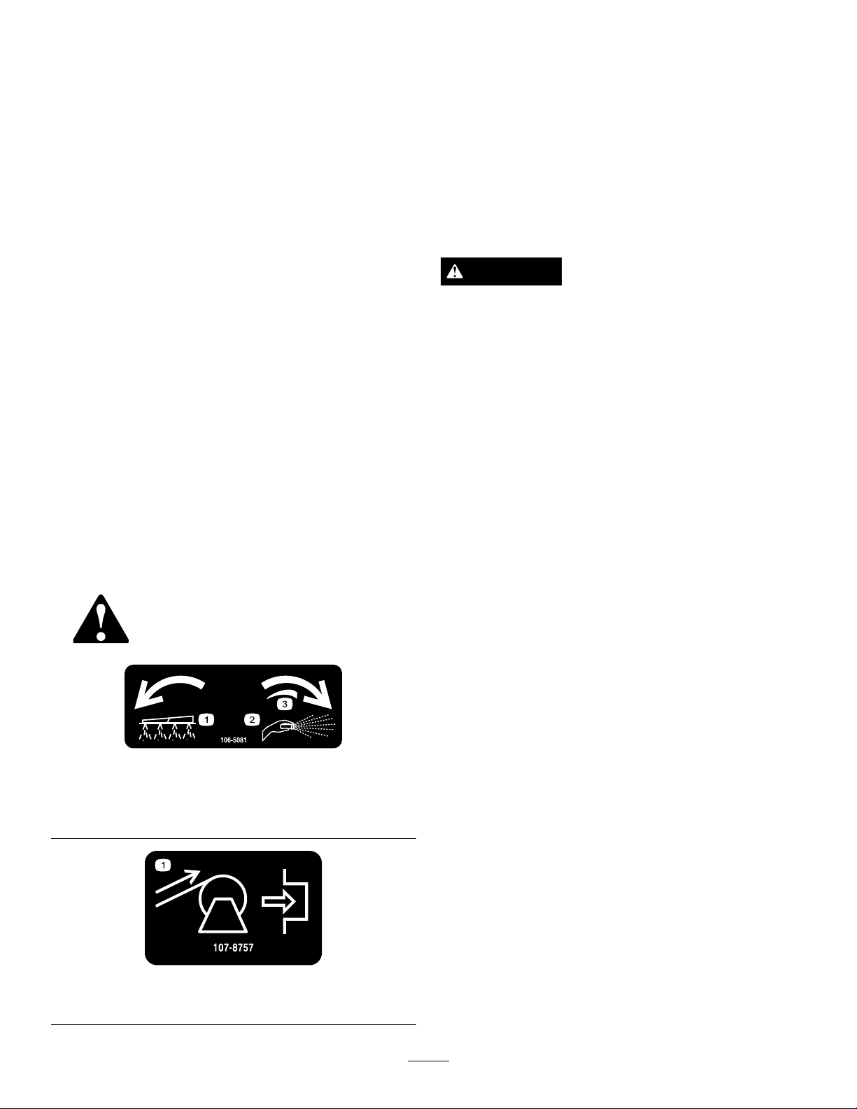
SwitchingfromBoomSpray
ModetoHandSprayMode
1.Stopthemachine,turntheboomsoffandsetthe
parkingbrake.
WARNING
Drivingwhileusingthehandsprayercancause
lossofcontrol,resultingininjuryordeath.Do
notoperatethehandsprayerwhiledriving.
2.Atthebackofthemachine,Ensurethatthetrigger
lockonthespraygunislocked.
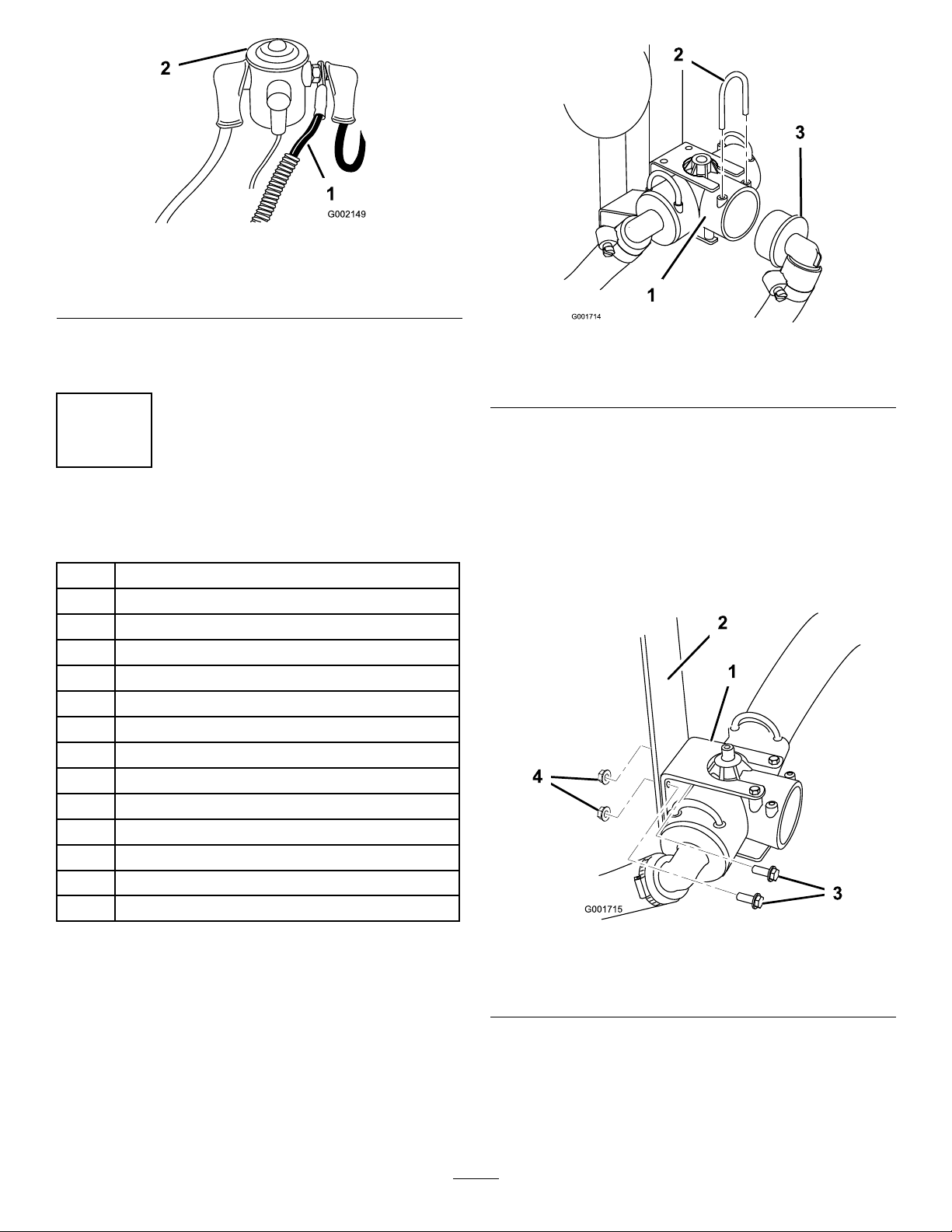
3.Turnthehandleonthefaceofthecontrolvalve
clockwisetotheHandSprayposition.
4.Attheoperator’sposition,turnthepumpon.
5.Increasetheenginespeeduntilthepressuregauge
readsthedesiredpsiandengagetheneutralengine
speedlock.
Important:Donotuseapressuresetting
higherthan150psiwiththehandsprayer.
Note:Usethepressuregaugewhileturningthe
controlvalvehandletoachievethedesiredamount
ofpressureathandsprayer.
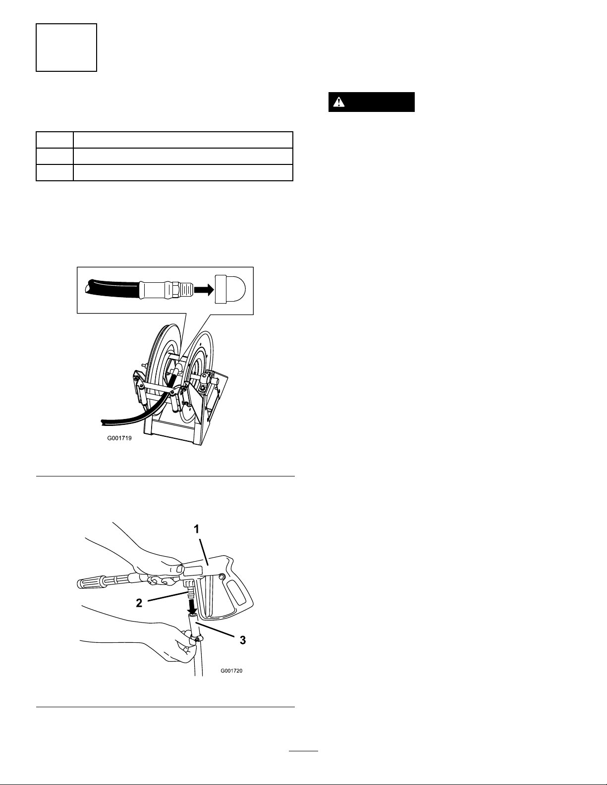
SprayingwiththeHand
Sprayer
1.Pulloutthedesiredamountofhosefromthereel.
Important:Donotpullthehosewiththe
spraygun.Alwaysholdthehoseandpullonit
directly.Pullingonthehosewiththegunmay
breakthettingonthegunordamagethehose.
2.Releasethetriggerlock.
3.Directthespraygunnozzleattheareatobesprayed
andpullthetrigger.
4.Releasethetriggerandsetthetriggerlockwhen
nished.
SwitchingfromHandSpray
ModetoBoomSprayMode
1.Presstherewindbuttononthehosereeluntilonly
afewfeetofhoseisoutofthereel.
CAUTION
Hands,looseclothing,longhair,andjewelry
couldgetcaughtinthehoseandreelwhile
rewindingandcauseinjury.
•Keepyourhandsclearofthereelandhose
whileitisrewinding.
•Donotwearlooseclothingorjewelryand
tieuplonghair.
2.Turnthehandleonthefaceofthecontrolvalve
counterclockwisetotheBoomSprayposition.
3.Directthespraygunnozzleatanareawhereitis
safetospray,releasethetriggerlock,andpullthe
triggeruntilallremaininguidisoutofthehose,
thensetthetriggerlock.
4.Returnthesprayguntotheholderonthebackof
thereel.
10

5.Returntheenginetoidlespeed.
6.Stopthepump.
Important:Ensurethatyouushthespray
gunwithfreshcleanwaterduringyour
dailycleaningroutine(refertoyoursprayer
Operator’ s Man ual
).Failuretoproperlyclean
thespraygunmaydegradetheperformance
andreliabilityofthehosereelkitandspraygun.
11

Table of contents
Other Toro Tools manuals