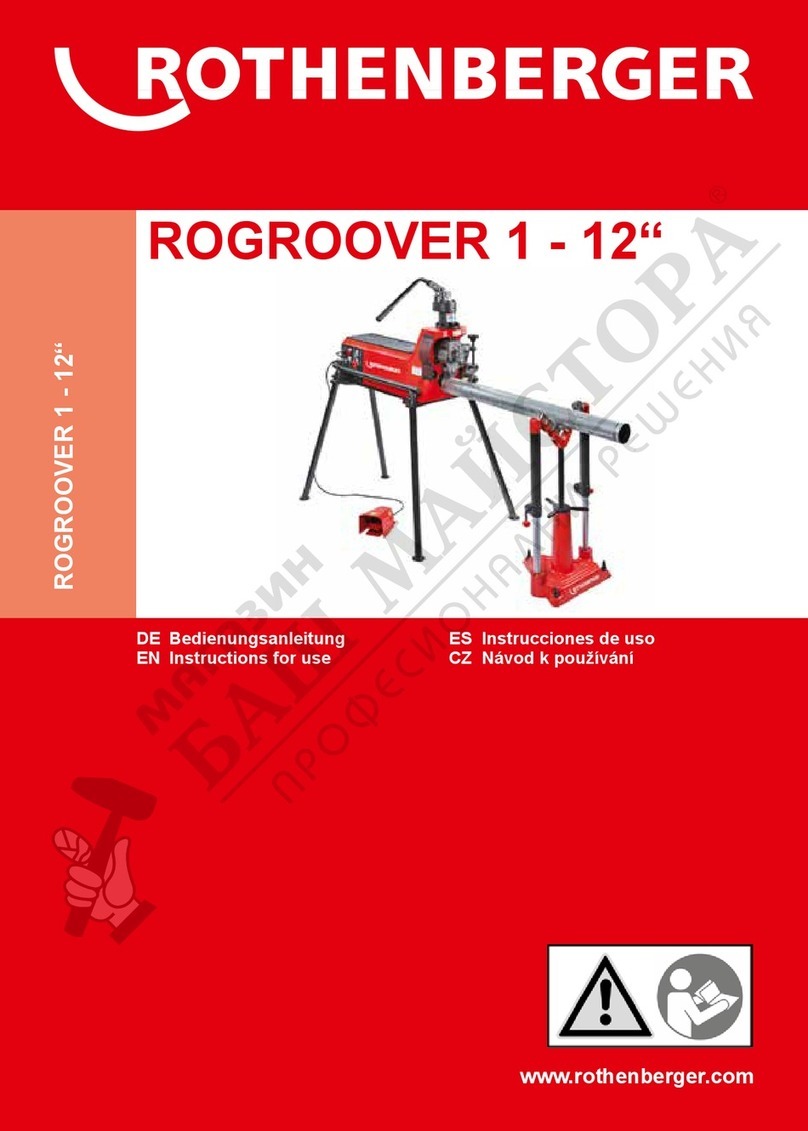
Rothenberger H600 User manual


2
Inhalt Seite
1.
Hinweise zur Sicherheit 3
1.1
Bestimmungsgemäßer Gebrauch 3
1.2
Spezielle Sicherheitshinweise 3
2.
Technische Daten 3
3.
Funktion des Gerätes 3
3.1
Geräteübersicht
(Abb. A)
3
3.2
Gerätebeschreibung 4
3.3
Inbetriebnahme 4
3.4
Wechsel des Aufweitdornes Pistole H2
(Abb. B)
5
3.5
Einstellen der Hydraulikpistolen H1 und H2
(Abb. C)
5
3.6
Außerbetriebnahme 6
4.
Pflege und Wartung 6
5.
Zubehör 6
6.
Entsorgung 6
7.
Elektroschaltplan 7
Kennzeichnungen in diesem Dokument
Gefahr
Dieses Zeichen warnt vor Personenschäden.
Achtung
Dieses Zeichen warnt vor Sach- oder Umweltschäden.
Î
Aufforderung zu Handlungen
DEUTSCH

3
1. Hinweise zur Sicherheit
1.1 Bestimmungsgemäßer Gebrauch
Das Elektrohydraulikgerät H600 ist nur in Verbindung mit den Elektrohydraulik-
Expanderpistolen H1 (im Lieferumfang 1.3100 enthalten) und H2 (als Zubehör erhältlich) zum
Aufweiten, Reduzieren und Kalibrieren von normal – und dickwandigen Rohren (max. 3mm) zu
verwenden. Das Gerät darf nur von qualifiziertem und unterwiesenem Fachpersonal betrieben
werden!
1.2 Spezielle Sicherheitshinweise
Allgemeine Sicherheitshinweise im Anhang
Safety
lesen und verstehen (
ab Seite 62
)!
Schließen Sie das Gerät auf dem Bau oder in Feuchträumen nur über einen FI - Schutzschalter
an!
Fremdwerkzeuge und Zubehör müssen die Zulassung bis min. 600 bar aufweisen!
Bevor Sie die Expanderpistole wechseln, darauf achten, dass das Gerät drucklos ist (Fuß vom
Fußschalter nehmen)!
Prüfen Sie den Expanderkopf vor Inbetriebnahme auf Beschädigungen! Kleinste
Beschädigungen können bei Betrieb zur Gefahr für Mensch und Umgebung werden!
Jeder Expanderkopf muss auf Einstellung vor dem Einsatz mit der Hydraulikpistole unbedingt
geprüft werden!
Rohre fest einlegen! Legen Sie die Rohre immer parallel, niemals schräg zur Expanderachse! Nie
in den unmittelbaren Arbeitsbereich greifen!
Arbeiten Sie grundsätzlich mit der schnell zu montierenden Werkzeugablage. Sie schützen sich
und andere vor Unfällen und Sie schonen damit die Werkzeuge!
2. Technische Daten
Nennstrom: 2,1 A
Nennaufnahme: 1,2 kW
Arbeitsdruck: 80-600 bar
Max. Betriebsdruck: 700 bar
Förderleistung: 0,82 l/min
Einschaltdauer: 100% - 80 bar
Schutzklasse: IP 54
3. Funktion des Gerätes
3.1 Geräteübersicht (Abb. A)
1
Stecker / Dose Fußschalter
7
Kontrollleuchte „
Einrichten
“
2
Stecker / Dose Werkzeugsteuerung
8
Kontrollleuchte „
Störung
“
3
Stromsicherungen 1,6 A / 0,25 A Tr.
9
Drehknopf Betriebsdruck
4
Schalter „
EIN
“ und „
AUS
“
10
Gehäuse
5
Schalter „
Einrichten
“ und
„
Automatik
“
11
Anschluss Hydraulikschlauch /
Schnellkupplung
6
Kontrollleuchte „
Betriebsbereit
“
12
Sicherheitsfußschalter
DEUTSCH

4
3.2 Gerätebeschreibung
Das ROTHENBERGER Elektrohydraulik – Gerät bzw. die Expanderanlage H 600 ist eine
universelle und mobile Anlage zum seriellen Aufweiten, Reduzieren und Kalibrieren von
normal- und dickwandigen Rohren für Industrie und Handwerk.
Sie besteht aus zwei Hauptgruppen:
1.
Hydraulikpumpe und Steuerung (1.3002 Elektrohydraulik – Gerät H600)
2.
Hydraulikpistole als Werkzeugträger (Expanderpistole H1 Nr. 1.2002 im Lieferumfang
Expanderanlage H600 Nr. 1.3100 enthalten, oder optional Expanderpistole H2 Nr.
1.2002/1.2003)
Das materialgerechte Arbeiten wird durch stufenlos und exakt einstellbaren Arbeitsdruck mit
Einricht- und Automatikbetrieb gewährleistet.
Folgende ROTHENBERGER Expanderköpfe sind verwendbar:
Werkzeugträger Expanderpistole H1 (im Lieferumfang 1.3100 enthalten)
Nieten-Expanderköpfe (Standard)
∅
8 –42mm
bzw.
5/16“ – 1 ¾“
bis
1,6mm
Wandstärke
Nieten-Expanderköpfe Typ S
∅
22-67mm
bzw.
7/8“ – 2 ½“
bis
2,5mm
Wandstärke
(nur Mittels Adapter Nr. 1.1007 )
Werkzeugträger Expanderpistole H2 Art.- Nr. 1.2002 (als Zubehör erhältlich)
Nieten-Expanderköpfe Typ S
∅
22-67mm
bzw.
7/8“ – 2 ½“
bis
2,5mm
Wandstärke
(nur mittels Adapter Nr. 1.2097 )
Nieten-Expanderköpfe H2 Typ 2
∅
28 –70mm
bzw.
1 1/8“ – 2 ¾“
bis
2,5mm
Wandstärke
Nieten-Expanderköpfe H2 Typ 3
∅
70 –110mm
bzw.
2 ¾“ – 4 ¼“
bis
3,0mm
Wandstärke
Werkzeugträger Expanderpistole H2 Art.- Nr. 1.2003 (als Zubehör erhältlich)
Stufenexpanderköpfe HA2
∅
28 –110mm
bzw.
1 1/8“ – 4 ¼“
bis
3,0mm
Wandstärke
3.3 Inbetriebnahme
Vor Erstinbetriebnahme des Gerätes die Ölbehälter-Transportschraube durch
beiliegenden Pumpen-Belüftungsfilter ersetzen, wie folgt:
Î
Die beiden Schrauben am Gehäuseoberteil
(11)
lösen und
Gehäuse nach hinten weg ziehen.
Î
Ölbehälterverschlussschraube
(A)
entfernen und durch
beiliegenden Luftfilter ersetzen.
Î
Rasthebel
(B)
des Überlastrelais
(C)
sicherheitshalber
bis
zum Anschlag durchdrücken, er könnte durch den
Transport gelöst sein.
Î
Gehäuse wieder befestigen.
Î
Stecker des Sicherheitsfußschalters
(12)
an die Flanschdose
(1)
am Gerät anschließen.
Î
Steuerkabel der Pistole mit der Flanschdose
(2)
am Gerät verbinden und durch
Druckdrehung sichern.
Î
Mittels Schnellkupplung
(11)
Hydraulikschlauch der Pistole am Gerät anschließen und
Netzkabel mit der Stromversorgung verbinden.
Die Hydraulikanlage ist nun betriebsbereit.
AC
B
DEUTSCH

5
Das Gerät ist nur mit der auf dem Typenschild angegebenen Spannung zu
betreiben! Das Stromnetz ist mit 10A abzusichern.
Bei Überlastung des Gerätes schaltet das Überlastungsrelais
(C)
automatisch ab und die
Störungskontrollleuchte
(8)
brennt:
Î
Netzstecker ziehen und Gehäuse
(10)
wie oben beschrieben entfernen.
Î
Rasthebel
(B)
bis zum Anschlag durchdrücken und Netzkabel wieder mit dem Stromnetz
verbinden.
3.4 Wechsel des Aufweitdornes Pistole H2 (Abb. B)
Die Verwendung Stufenexpander HA 2 (nur in Verbindung mit Pistole H2)
ist nur mit langen Aufweitdorn zulässig! Verstellschraube muss komplett
herausgedreht sein!
Aufweitdorn wechseln:
Î
Schalter
(5)
auf Einrichten und Fußschalter
(12)
betätigen.
Fußschalter während des Arbeitsganges immer gedrückt halten!
Î
Mikroschalter an der Hydraulikpistole kurz antippen, sodass Aufweitdorn bis zum Anschlag
nach vorne fährt
(Bild 1)
.
Gerät schaltet bei Erreichung des eingestellten Druckes automatisch ab!
Î
Aufweitdorn abschrauben und innen liegende Verstellschraube mittels Einstellschlüssel
einstellen: Langer Aufweitdorn= komplett herausdrehen
(Bild 2)
, kurzer Aufweitdorn=
komplett hereindrehen.
Î
Aufweitdorn bis zum Anschlag aufschrauben
(Bild 3)
3.5 Einstellen der Hydraulikpistolen H1 und H2 (Abb. C)
Voreinstellung überprüfen:
Î
Den zu verwendeten Expanderkopf auf Hydraulikpistole bis zum Anschlag aufschrauben.
Die Segmente des Expanderkopfes dürfen im eingefahren Zustand nicht gespreizt sein.
Mittels Einstellschlüssel kann die Verstellmutter der Pistole eingestellt werden, die das Aus-
und Einfahren des Aufweitdornes reguliert.
Î
Expanderkopf wieder abschrauben.
Einstellen:
Î
Betriebsschalter
(4)
auf EIN und Betriebsdruck mittels Drehknopfes
(9)
auf 80 bar einstellen.
Î
Schalter
(5)
auf Einrichten und Fußschalter
(12)
betätigen.
Fußschalter während des Arbeitsganges immer gedrückt halten!
Î
Mikroschalter an der Hydraulikpistole kurz antippen, sodass Aufweitdorn bis zum Anschlag
nach vorne fährt
(Bild 1)
.
Gerät schaltet bei Erreichung des eingestellten Druckes automatisch ab!
Î
Expanderkopf fest auf die Pistole schrauben und Fußschalter
(12)
loslassen, um den Druck
wieder abzubauen (Aufweitkolben geht wieder in die Ausgangsposition zurück)
(Bild 2)
.
Î
Der Expanderkopf ist richtig eingestellt, wenn man ihn noch 1/3 – ½ Umdrehung bis zum
Anschlag nach rechts drehen kann
(Bild 3)
.
DEUTSCH

6
Immer eine Probeaufweitung durchführen, um festzustellen, ob der geforderte
Aufweitdurchmesser erreicht wurde. Abweichungen mittels Einstellschlüssel an
der Verstellmutter der Pistole korrigieren!
Î
Ist der entsprechende Expanderkopf (wie oben beschrieben) richtig eingestellt, den Schalter
(5)
auf „AUTOMATIK“ stellen.
Î
Rohr über Expanderkopf schieben und Fußschalter kurz antippen.
Der Aufweitkolben der Expanderpistole fährt automatisch, bis der eingestellte Druck erreicht
ist, vor und anschließend wieder zurück.
Auf die richtige Expanderkopfgröße achten!
Expanderkopfgröße muss dem Auf-
zuweitenden Rohr entsprechen!
Hinweis: Der Arbeitstakt sollte nicht unter 1 Minute sein.
3.6 Außerbetriebnahme
Î
Fuß von dem Sicherheitsfußschalter nehmen und / oder die Hand vom Mikroschalter.
Î
Schalter
(4)
auf AUS stellen, Netzkabel ziehen und Anschlüsse
(1,2,11)
entfernen.
Geräte sicher aufbewahren.
4. Pflege und Wartung
Î
Ölstand nach ca. 300 Betriebsstunden überprüfen: Luftfilter
(A)
aus dem Pumpengehäuse
schrauben und Ölstand am Ölmessstab prüfen.
Î
Öl grundsätzlich durch einen Trichter nachfüllen.
Nicht über die Markierung befüllen!!
Î
Ein Ölwechsel ist alle 1500 Betriebsstunden vorzunehmen! Hierzu nur das ROTHENBERGER
Spezialhydrauliköl
Art.-Nr.: 5.8185
verwenden.
Î
Alle Rohrverschraubungen sind nach den ersten 500 Betriebsstunden nachzuziehen!
Es stehen Ihnen die Rothenberger- Servicestationen oder der Hersteller mit seiner
Reparaturabteilung zur Verfügung. Selbstverständlich schicken wir Ihnen auch umgehend
Ersatzteile zu. Wenden Sie sich bitte an Ihren Händler oder den Hersteller.
Bestellen Sie Ihre Zubehör und Ersatzteile bei Ihrem Fachhändler oder bei unserer Hot – Line
Service After Sales
Tel.
+49 6195 99 52
14
Fax:
+49 6195 99 52
15
5. Zubehör
Geeignetes Zubehör und ein Bestellformular finden Sie ab Seite 80.
6. Entsorgung
Teile des Gerätes sind Wertstoffe und können der Wiederverwertung zugeführt werden. Hierfür
stehen zugelassene und zertifizierte Verwerterbetriebe zur Verfügung. Zur umweltver-
träglichen Entsorgung der nicht verwertbaren Teile (z.B. Elektronikschrott) befragen Sie bitte
Ihre zuständige Abfallbehörde.
Für die Entsorgung von Altölen sind ausschließlich Fachbetriebe zugelassen! Altöle und
verunreinigte Öle müssen in dichten, ölbeständigen Behältern (Metallgebinden) aufbewahrt
und entsorgt werden! Öle (auch Kleinstmengen) dürfen keinesfalls in das Erdreich gelangen!
DEUTSCH

7
Für die Entsorgung von Abfällen aus Instandhaltungsarbeiten sind die von der jeweiligen
Behörde auf Landes -und Bundesebene erlassenen Vorschriften einzuhalten! Zu erfragen sind
diese bei der ortsansässigen Umweltbehörde!
Im Zweifelsfall sind aus Instandhaltungsarbeiten anfallende Abfälle wie Reinigungs- und
Spülmittel, Putzlappen etc. als Sonderabfälle durch kommunale Sammelstellen zu entsorgen!
Verwertbare Abfälle müssen nach Stoffgruppen getrennt und einer geeigneten
Wiederverwertung zugeführt werden!
Nur für Deutschland gültig:
Die Entsorgung Ihres erworbenen ROTHENBERGER Gerätes übernimmt ROTHENBERGER für Sie -
kostenlos! Bitte geben Sie dies bitte bei Ihrem nächsten ROTHENBERGER Service Express Händler
ab.
Wer Ihr ROTHENBERGER Service Express Händler in Ihrer Nähe ist, erfahren Sie auf unserer
Homepage unter
www.rothenberger.com
7. Elektroschaltplan
DEUTSCH

8
Contens page
1.
Safety information 9
1.1
Use in accordance with the intended purpose 9
1.2
Special safetey instruction 9
2.
Technical data 9
3.
Function of the device 9
3.1
Overview
(fig. A)
9
3.2
Device description 10
3.3
Putting into operation 10
3.4
Changing the expanding mandrel pistol H2
(Fig. B)
11
3.5
Adjusting the hydraulic pistols H1 and H2
(Fig. C)
11
3.6
Taking out of service 12
4.
Maintenance and upkeep 12
5.
Accessories 12
6.
Disposal 12
7.
Electrical wiring diagram 13
Markings in this document
Danger
This sign warns against the danger of personal injuries.
Caution
This sign warns against the danger of property damage and damage to the
environment.
Î
Call for action
ENGLISH

9
1. Safety information
1.1 Use in accordance with the intended purpose
The H600 electrohydraulic device should only be used in combination with the electrohydraulic
expander pistols H1 (included in the scope of supplies of the 1.3100) and H2 (available as an
accessory) for the expanding, reducing and calibrating of normal and thick-walled pipes (max. 3
mm). The device may only be operated by skilled and instructed qualified personnel!
1.2 Special safetey instruction
Please be sure to read and understand the general safety information in the addendum on
safety
(from
page 62
onward).
On the building site or in damp rooms only connect the device via a FI protective circuit
breaker!
Third-party tools and accessories must have approval up to at least 600 bar!
Before changing the expander pistol, it is essential that the device is depressurised (take the
foot from the foot-operated switch)!
Check the expander head for damage before putting into operation! Any minimal damage can
become a danger to persons and the surroundings during operation!
Each expander head must always be checked for adjustment before using with the hydraulic
pistol!
Insert pipes firmly! Always lay the pipes parallel, never at an angle to the expander axis! Never
reach into the immediate working area!
Always work with the quickly assembled tool tray. You will protect yourself and other persons
from accidents and in doing so take good care of the tools!
2. Technical data
Nominal current: 2.1 A
Rated power input: 1.2 kW
Working pressure: 80-600 bar
Max. operating pressure: 700 bar
Delivery rate: 0.82 l/min
Operating time: 100% - 80 bar
Class of protection: IP 54
3. Function of the device
3.1 Overview (fig. A)
1
Plug / socket foot-operated switch
7
Indicator lamp “
Setting up
”
2
Plug / socket tool control system
8
Indicator lamp “
Fault
”
3
Fuses 1.6 A / 0.25 A slow-blowing
9
Rotary knob operating pressure
4
Switch “ON” and “OFF”
10
Housing
5
Switch “
Setting up
” and “
Automatic
”
11
Connection hydraulic hose / quick
coupling
6
Indicator lamp “
Ready for operation
”
12
Safety foot-operated switch
ENGLISH

10
3.2 Device description
The ROTHENBERGER electrohydraulic device, that is to say the H 600 expander system, is a
universal and mobile system for the serial expanding, reducing and calibrating of normal and
thick-walled pipes for trade and industry.
It consists of two main groups:
1.
Hydraulic pump and control system (1.3002 electrohydraulic device H600)
2.
Hydraulic pistol as tool carrier (expander pistol H1 no. 1.2002 included in the scope of
supplies of the H600 expander system no. 1.3100, or optional expander pistol H2 no.
1.2002/1.2003)
Working which is appropriate for the material involved is ensured as a result of the infinitely
variable and precisely adjustable working pressure with setting up and automatic operation.
The following ROTHENBERGER expander heads can be used:
Tool carrier expander pistol H1 (included in the scope of supplies of the 1.3100)
Rivet expander heads (standard)
∅
8 –42 mm
and
5/16“ – 1 ¾“
to
1.6 mm
wall thickness
Rivet expander heads type S
∅
22-67 mm
and
7/8“ – 2 ½“
to
2.5 mm
wall thickness
(only with the aid of adapter no. 1.1007 )
Tool carrier expander pistol H2 prod. no. 1.2002 (available as an accessory)
Rivet expander heads type S
∅
22-67 mm
and
7/8“ – 2 ½“
to
2.5 mm
wall thickness
(only with the aid of adapter no. 1.2097 )
Rivet expander heads H2 type 2
∅
28 –70 mm
and
1 1/8“ – 2 ¾“
to
2.5 mm
wall thickness
Rivet expander heads H2 type 3
∅
70 –110 mm
and
2 ¾“ – 4 ¼“
to
3.0 mm
wall thickness
Tool carrier expander pistol H2 prod. no. 1.2003 (available as an accessory)
Stepped expander heads HA2
∅
28 –110 mm
and
1 1/8“ – 4 ¼“
to
3.0 mm
wall thickness
3.3 Putting into operation
Prior to initial operation of the device, replace the oil reservoir transport screw
with the pump aeration filter as follows:
Î
Unscrew the two screws on the upper part of the housing
(11)
and remove the housing towards the back.
Î
Remove oil reservoir screw plug
(A)
and replace with the
air filter provided.
Î
As a precaution, push the notch lever
(B)
of the
overload
relay
(C)
through
as far as the end stop; it could have been
loosened by the transport.
Î
Reattach the housing.
Î
Connect the plug of the safety foot-operated switch
(12)
to
the flange socket
(1)
on the device.
Î
Connect the control cable of the pistol to the flange socket
(2)
on the device and secure by
pressing and turning.
Î
Connect the hydraulic hose of the pistol to the device with the aid of the quick coupling
(11)
and connect the power cable to the power supply.
The hydraulic system is now ready for operation.
AC
B
ENGLISH

11
The device should only be operated at the voltage stated on the type plate! The
power supply should be protected by a 10A fuse.
In case of overloading of the device, the overload relay
(C)
switches off automatically and the
fault indicator lamp
(8)
lights up:
Î
Disconnect the mains plug and remove the housing
(10)
as described above.
Î
Push the notch lever
(B)
through as far as the end stop and re-connect the power cable to
the power supply.
3.4 Changing the expanding mandrel pistol H2 (Fig. B)
Use of the stepped expander HA 2 (only in combination with pistol H2) is
only permitted with a long expanding mandrel! The adjusting screw must
be completely unscrewed!
Changing the expanding mandrel:
Î
Turn switch
(5)
to setting up mode and operate foot-operated switch
(12)
.
Always hold the foot-operated switch depressed during the working cycle!
Î
Press the microswitch on the hydraulic pistol momentarily, so that the expanding mandrel
travels to the front as far as the end stop
(Illustration 1)
.
The device switches off automatically on reaching the set pressure!
Î
Unscrew the expanding mandrel and adjust the internal adjusting screw with the aid of the
adjusting spanner: Long expanding mandrel= unscrew completely
(Illustration 2)
, short
expanding mandrel= screw in completely.
Î
Screw on the expanding mandrel as far as the end stop
(Illustration 3)
3.5 Adjusting the hydraulic pistols H1 and H2 (Fig. C)
Checking the preadjustment:
Î
Screw the expander head which is to be used onto the hydraulic pistol as far as the end
stop.
The segments of the expander head must not be expanded in the retracted state. The
adjusting nut of the pistol, which regulates the extension and retraction of the expanding
mandrel, can be adjusted using the adjusting spanner.
Î
Unscrew the expander head again.
Adjusting:
Î
Turn operating switch
(4)
to ON and adjust operating pressure to 80 bar using rotary knob
(9)
.
Î
Turn switch
(5)
to setting up mode and operate foot-operated switch
(12)
.
Always hold the foot-operated switch depressed during the working cycle!
Î
Press the microswitch on the hydraulic pistol momentarily, so that the expanding mandrel
travels to the front as far as the end stop
(Illustration 1)
.
The device switches off automatically on reaching the set pressure!
Î
Screw the expander head tightly onto the pistol and release the foot-operated switch
(12)
to relieve the pressure again (expansion piston returns to the initial position again)
(Illustration 2)
.
ENGLISH

12
Î
The expander head is adjusted correctly if it can be turned another 1/3 – ½ of a rotation to
the right as far as the end stop
(Illustration 3)
.
Always carry out an experimental expansion to determine whether the required
expansion diameter has been achieved. Correct any deviations using the adjusting
spanner on the adjusting nut of the pistol!
Î
If the appropriate expander head (as described above) has been adjusted correctly, turn the
switch
(5)
to “AUTOMATIC”.
Î
Push the pipe over the expander head and press the foot-operated switch momentarily.
The expansion piston of the expander pistol travels automatically forwards and subsequently
back again until the set pressure has been reached.
Please pay attention to the correct expander head size!
The expander head size must
match the pipe which is to be expanded!
Note: The phase time should not be less than 1 minute.
3.6 Taking out of service
Î
Take the foot from the safety foot-operated switch and / or the hand from the microswitch.
Î
Turn the switch
(4)
to OFF, disconnect the power cable and remove the connections
(1,2,11)
.
Keep the devices in a safe place.
4. Maintenance and upkeep
Î
Check the oil level after approx. 300 operating hours: unscrew the air filter
(A)
from the
pump housing and check the oil level on the dipstick.
Î
Always top the oil up through a funnel.
Do not fill above the mark!!
Î
An oil change should be carried out every 1500 operating hours! Only use the
ROTHENBERGER special hydraulic fluid
prod. no.: 5.8185
for this purpose.
Î
All tube fittings are to be retightened after the first 500 operating hours!
The assistance of the Rothenberger service stations or the repair department of the
manufacturer are available to you. We will, of course, also immediately send spare parts to you.
Please contact either your dealer or the manufacturer.
Order your accessories and spare parts at your specialist dealer or via our After Sales hotline
Tel.
+49 6195 99 52
14
Fax:
+49 6195 99 52
15
5. Accessories
The relevant accessories and an order form can be found from Page 80 onwards.
6. Disposal
Components of the unit are recyclable material and should be put to recycling. For this purpose
registered and certified recycling companies are available. For an environmentalfriendly
disposal of the non-recyclable parts (e.g. electronic waste) please contact your local waste
disposal authority.
ENGLISH

13
Only specialist companies are authorised to dispose of old oils. Old oils and contaminated oils
must be stored and disposed of in sealed, oil-resistant containers (metal drums). Defective
electrical appliances and machines that cannot be repaired must be opened and cleaned to
remove the remaining oil. Oil troughs must be cleaned so that there are no traces of oil. No oils
(even very small amounts) may be allowed to enter the ground.
Regulations issued by the responsible national and regional authorities for disposing of refuse
must be observed. These are available from the local environmental authority. If in doubt,
waste from maintenance work such as cleaning and rinsing agents, cloths etc. must be disposed
of as special category waste by communal collecting points. Waste that can be recycled must be
separated on the basis of material groups and sent for suitable recycling!
7. Electrical wiring diagram
ENGLISH
Bush foot-
operated switch
Bush handle
red Yell-
ow
green

14
Table des matières Page
1.
Remarques concernant la sécurité 15
1.1
Utilisation conforme à la destination 15
1.2
Remarques particulières concernant la sécurité 15
2.
Caractéristiques techniques 15
3.
Fonctionnement de l'appareil 15
3.1
Vue d'ensemble de l'appareil
(ill. A)
15
3.2
Description de l'appareil 16
3.3
Mise en service 16
3.4
Echange de la broche de mandrin pistolet H2
(ill. B)
17
3.5
Réglage des pistolets hydrauliques H1 et H2
(ill. C)
17
3.6
Mise hors service 18
4.
Entretien et maintenance 18
5.
Accessoires 18
6.
Elimination des déchets 18
7.
Schéma de câblage électrique 19
Pictogrammes contenus dans ce document
Danger
Ce pictogramme signale un risque de blessure pour les personnes.
Attention
Ce pictogramme signale un risque de dommage matériel ou de
préjudice pour l’environnement.
Î
Nécessité d’exécuter une action
FRANÇAIS

15
1. Remarques concernant la sécurité
1.1 Utilisation conforme à la destination
L'appareil électrohydraulique H600 doit être utilisé uniquement en liaison avec les pistolets
d'expansion électrohydrauliques H1 (inclus dans la livraison 1.3100) et H2 (disponible en tant
qu'accessoire) pour élargir, réduire et calibrer les tubes normaux et à paroi épaisse (max. 3 mm).
L'appareil ne doit être utilisé que par du personnel spécialisé, qualifié et instruit!
1.2 Remarques particulières concernant la sécurité
Lire et bien assimiler les remarques générales concernant la sécurité dans l'annexe
Safety
(à
partir de la
page 62
)!
Sur le chantier ou dans des locaux humides l'appareil doit être raccordé uniquement au moyen
d'un interrupteur PRCD (FI en Suisse) !
Les outils étrangers et les accessoires doivent être agréés pour supporter un minimum de 600
bars!
Avant de changer le pistolet d'expansion, veiller à ce que l'appareil ne soit plus sous pression
(retirer votre pied de l'interrupteur à pied)!
Avant la mise en service, vérifier que la tête d'expansion ne présente aucune détérioration! La
moindre détérioration peut représenter un danger pour l'homme et l'environnement pendant
le fonctionnement!
Avant de commencer à travailler avec le pistolet hydraulique, contrôler impérativement le
réglage de chaque tête d'expansion!
Introduire fermement les tubes! Toujours placer les tubes parallèlement par rapport à l'axe du
pistolet d'expansion, jamais en position oblique! Ne jamais mettre les mains à proximité
immédiate de l'emplacement de travail!
Travailler essentiellement en utilisant le système de rangement d'outil, rapide à monter. Vous
éviterez les risques d'accident pour vous et pour les autres personnes, et vous ménagerez ainsi
les outils!
2. Caractéristiques techniques
Courant nominal: 2,1 A Régime permanent: 100% - 80 bars
Prise de courant nominale: 1,2 kW Classe de protection: IP 54
Pression de service: 80-600 bars
Pression max. de fonctionnement: 700 bars
Débit: 0,82 l/min
3. Fonctionnement de l'appareil
3.1 Vue d'ensemble de l'appareil (ill. A)
1
Connecteur / Prise de courant interrupteur à
pied
7
Témoin lumineux "
Réglage
"
2
Connecteur / Prise de courant commande de
l'outil
8
Témoin lumineux "
Dysfonctionnement
"
3
Fusibles 1,6 A / 0,25 A à action retardée
9
Bouton de réglage de la pression de
fonctionnement
4
Interrupteur "
MARCHE
" et "
ARRET
"
10
Carter
5
Interrupteur "
Réglage
" et "
Automatique
"
11
Raccord du tuyau hydraulique / Raccord
rapide
6
Témoin lumineux "
Prêt à fonctionner
"
12
Interrupteur à pied de sécurité
FRANÇAIS

16
3.2 Description de l'appareil
L'appareil électrohydraulique ROTHENBERGER - ou bien l'installation d'expansion H 600 - est
une installation universelle et mobile permettant d'élargir, de réduire et de calibrer en série
pour l'industrie et l'artisanat des tubes normaux et à paroi épaisse.
Elle comprend deux groupes principaux:
1.
Pompe hydraulique et commande (1.3002 appareil électrohydraulique H600)
2.
Pistolet hydraulique servant de support d'outil (pistolet d'expansion H1 n° 1.2002 compris
dans la livraison de l'installation d'expansion H 600 n° 1.3100, ou en option pistolet
d'expansion H2 n° 1.2002/1.2003)
L'adaptation du travail aux matériaux est assurée par une pression de travail en continu et
réglable avec précision, avec fonctionnement de réglage et fonctionnement automatique.
Les têtes d'expansion ROTHENBERGER suivantes peuvent être utilisées:
Support d'outil pistolet d'expansion H1 (compris dans la livraison 1.3100)
Têtes d'expansion pour rivets (Standard)
∅
8 –42mm
ou bien
5/16“ – 1 ¾“
jusqu'à
1,6 mm
d'épaisseur
Têtes d'expansion pour rivets type S
∅
22-67 mm
ou bien
7/8“ – 2 ½“
jusqu'à
2,5 mm
d'épaisseur (uniquement avec l'adaptateur n° 1.1007 )
Support d'outil pistolet d'expansion H2 réf. 1.2002 (disponible en tant qu'accessoire)
Têtes d'expansion pour rivets type S
∅
22-67 mm
ou bien
7/8“ – 2 ½“
jusqu'à
2,5 mm
d'épaisseur (uniquement avec l'adaptateur n° 1.2097 )
Têtes d'expansion pour rivets H2 type 2
∅
28 –70 mm
ou bien
1 1/8“ – 2 ¾“
jusqu'à
2,5 mm
d'épaisseur
Têtes d'expansion pour rivets H2 type 3
∅
70 –110 mm
ou bien
2 ¾“ – 4 ¼“
jusqu'à
3,0 mm
d'épaisseur
Support d'outil pistolet d'expansion H2 réf. 1.2003 (disponible en tant qu'accessoire)
Têtes d'expansion par palier HA2
∅
28 –110 mm
ou bien
1 1/8“ – 4 ¼“
jusqu'à
3,0 mm
épaisseur
3.3 Mise en service
Avant la première mise en service de l'appareil, remplacer la vis de transport du
récipient d'huile par le filtre d'aération de pompe joint, en procédant comme suit:
Î
Dévisser les deux vis de la partie supérieure du carter
(11)
et retirer le carter vers l'arrière.
Î
Oter la vis de fermeture du récipient d'huile
(A)
et la
remplacer par le filtre à air joint.
Î
Par précaution, enfoncer jusqu'à la butée le levier de
blocage
(B)
du relais de surcharge
(C),
car il est possible
qu'il ait bougé pendant le transport.
Î
Fixer à nouveau le carter.
Î
Raccorder l'interrupteur à pied de sécurité
(12)
à la prise de
courant femelle à bride
(1)
de l'appareil.
Î
Relier le câble de commande du pistolet à l'appareil au moyen de la prise de courant
femelle à bride
(2)
et le sécuriser par une rotation en pression.
Î
Raccorder le tuyau hydraulique du pistolet à l'appareil au moyen du raccord rapide
(11)
et
relier le câble secteur à l'alimentation électrique.
L'installation hydraulique est maintenant prête à fonctionner.
A
C
B
FRANÇAIS

17
Faire fonctionner l'appareil en utilisant uniquement la tension indiquée sur la
plaque signalétique! Le réseau doit être sécurisé avec 10 A.
En cas de surcharge de l'appareil, le relais de surcharge
(C)
se déconnecte automatiquement et
le témoin lumineux de dysfonctionnement
(8)
s'allume:
Î
Retirer la prise du secteur et ôter le carter
(10)
comme décrit ci-dessus.
Î
Enfoncer le levier de blocage
(B)
jusqu'à la butée et relier à nouveau le câble électrique
avec le réseau.
3.4 Echange de la broche de mandrin pistolet H2 (ill. B)
L'utilisation des têtes d'expansion par palier HA 2 (uniquement en liaison
avec le pistolet H2) est autorisée uniquement avec la broche de mandrin
longue! La vis de réglage doit être entièrement dévissée!
Echange de la broche de mandrin:
Î
Positionner l'interrupteur
(5)
sur réglage et actionner l'interrupteur à pied
(12)
.
Pendant la phase de travail, maintenir en permanence l'interrupteur à pied
enfoncé!
Î
Tapoter légèrement le commutateur miniature du pistolet hydraulique, de manière à ce que
la broche de mandrin s'avance jusqu'à la butée
(illustration 1)
.
L'appareil se déconnecte automatiquement lorsque la pression réglée est atteinte!
Î
Dévisser la broche de mandrin et régler la vis de réglage intérieure au moyen de la clé de
réglage: broche de mandrin longue = dévisser complètement
(illustration 2)
, broche de
mandrin courte = visser complètement.
Î
Visser la broche de mandrin jusqu'à la butée
(illustration 3)
3.5 Réglage des pistolets hydrauliques H1 et H2 (ill. C)
Vérifier le préréglage:
Î
Visser jusqu'à la butée sur le pistolet hydraulique la tête d'expansion à utiliser.
Lorsqu'ils sont en position rentrée les segments de la tête d'expansion ne doivent pas être
écartés. L'écrou de réglage du pistolet, qui régule l'entrée et la sortie de la broche de
mandrin, peut être réglé au moyen de la clé de réglage.
Î
Revisser la tête d'expansion.
Réglage:
Î
Positionner l'interrupteur
(4)
sur MARCHE et régler la pression de fonctionnement sur 80
bars au moyen du bouton de réglage
(9)
.
Î
Positionner l'interrupteur
(5)
sur réglage et actionner l'interrupteur à pied
(12)
.
Pendant la phase de travail, maintenir en permanence l'interrupteur à pied
enfoncé!
Î
Tapoter légèrement le commutateur miniature du pistolet hydraulique, de manière à ce que
la broche de mandrin s'avance jusqu'à la butée
(illustration 1)
.
L'appareil se déconnecte automatiquement lorsque la pression réglée est atteinte!
Î
Visser fermement la tête d'expansion sur le pistolet et relâcher l'interrupteur à pied
(12)
afin de laisser retomber la pression (le piston d'élargissement revient dans la position
initiale)
(illustration 2)
.
Î
La tête d'expansion est correctement réglée si l'on peut encore la tourner vers la droite de
1/3 à 1/2 tour jusqu'à la butée
(illustration 3)
.
FRANÇAIS

18
Toujours effectuer un élargissement d'essai pour voir si le diamètre
d'élargissement requis a pu être atteint. Corriger les différences à l'écrou de
réglage du pistolet au moyen de la clé de réglage!
Î
Si la tête d'expansion appropriée (comme décrit ci-dessus) est correctement réglée, placer
l'interrupteur
(5)
sur "AUTOMATIQUE".
Î
Placer le tube sur la tête d'expansion et tapoter légèrement l'interrupteur à pied.
Le piston d'élargissement du pistolet d'expansion avance et recule ensuite automatiquement
jusqu'à ce que la pression réglée soit atteinte.
Veiller à utiliser une tête d'expansion de dimension appropriée!
La dimension de la
tête d'expansion doit être adaptée au tube à élargir!
Remarque: la cadence de travail ne doit pas être inférieure à 1 minute.
3.6 Mise hors service
Î
Retirer votre pied de l'interrupteur à pied de sécurité et / ou retirer votre main du
commutateur miniature.
Î
Placer l'interrupteur
(4)
sur ARRET, débrancher le câble électrique et ôter les raccords
(1, 2, 11)
.
Ranger l'appareil en lieu sûr.
4. Entretien et maintenance
Î
Vérifier le niveau d'huile après environ 300 heures de fonctionnement: dévisser le filtre à air
(A)
du carter de la pompe et contrôler le niveau d'huile en vous servant de la jauge de
niveau d'huile.
Î
Toujours utiliser un entonnoir pour recompléter l'huile.
Ne pas dépasser le repère!!
Î
L'huile doit être changée toutes les 1500 heures de fonctionnement! Utiliser exclusivement
l'huile hydraulique spéciale ROTHENBERGER
réf.: 5.8185
.
Î
Resserrer tous les raccords vissés après les premières 500 heures de fonctionnement!
Les stations service de Rothenberger ou le département réparations du fabricant sont à votre
disposition. Nous vous ferons bien sûr parvenir les pièces de rechange dans les meilleurs délais.
Veuillez vous adresser à votre commerçant ou au fabricant.
Commandez vos accessoires et pièces de rechange chez votre revendeur spécialisé ou par
l'intermédiaire de la hotline du service après-vente
Tél.
+49 6195 99 52
14
Fax:
+49 6195 99 52
15
5. Accessoires
Vous trouverez les accessoires appropriés et un formulaire de commande page 80 et suivantes.
6. Elimination des déchets
Certaines pièces de l’appareil sont recyclables et peuvent donc faire l’objet d’un traitement de
recyclage. Des entreprises de recyclage agréées et certifées sont disponibles à cet effet.
Renseignez-vous auprès de votre administration de déchets compétente pour l’élimination non
polluante des pièces non recyclables (par ex. déchets électroniques).
Seules des entreprises spécialisées dans l’élimination des huiles usagées sont agréées ! Les huiles
usagées et les huiles contaminées doivent être conservés et éliminées dans des récipients
résistants à l’huile (fûts métalliques) !
FRANÇAIS
This manual suits for next models
5
Table of contents
Languages:
Other Rothenberger Tools manuals

Rothenberger
Rothenberger Ro-Groover 1-12 User manual

Rothenberger
Rothenberger Rogroover User manual

Rothenberger
Rothenberger SIEVERT PRO 9 User manual

Rothenberger
Rothenberger 5.6271 User manual

Rothenberger
Rothenberger ROMAX Compact TT User manual

Rothenberger
Rothenberger ROBEND 4000 E User manual

Rothenberger
Rothenberger COLLINS CLASSIC 22A User manual

Rothenberger
Rothenberger ROFROST Turbo R290 28 UK User manual

Rothenberger
Rothenberger ROWELD ROFUSE Sani 160 User manual

Rothenberger
Rothenberger 2224.04 User manual