Iluminarc 36X3 User manual

www.ILUMINARC.com
(954) 923-3680
Ilumipanel 36X3 IP Optic RGB
USER MANUAL

Ilumipod 36X3 IP Optic RGB User Manual 2 5/21/2009 11:44 AM
TABLE OF CONTENTS
1. Before You Begin..................................................................................................................................................................3
What is included..........................................................................................................................................................................3
Unpacking Instructions ...............................................................................................................................................................3
Safety Instructions ......................................................................................................................................................................4
2. Introduction ...........................................................................................................................................................................5
Features ......................................................................................................................................................................................5
DMX Channel Summary.............................................................................................................................................................6
Product Overview........................................................................................................................................................................8
3. SETUP ....................................................................................................................................................................................9
AC Power ....................................................................................................................................................................................9
Mounting....................................................................................................................................................................................10
Orientation.................................................................................................................................................................................10
Rigging ......................................................................................................................................................................................10
Stacking.....................................................................................................................................................................................11
Fixture Linking...........................................................................................................................................................................12
Data Cabling .............................................................................................................................................................................12
DMX Data Cable.......................................................................................................................................................................12
Cable Connectors .....................................................................................................................................................................12
3-Pin to 5-Pin Conversion Chart...............................................................................................................................................13
Setting up a DMX Serial Data Link...........................................................................................................................................13
Master/Slave Fixture Linking ....................................................................................................................................................13
4. Operating Instructions.......................................................................................................................................................14
Control Options.........................................................................................................................................................................14
DMX-512 control without ID address .......................................................................................................................................14
DMX-512 addressing with ID address......................................................................................................................................14
Setting the DMX address..........................................................................................................................................................15
Control Panel Functions ...........................................................................................................................................................15
Menu Map .................................................................................................................................................................................16
Manual Power ON/OFF ............................................................................................................................................................16
DMX512 Channel Values .........................................................................................................................................................17
STAGE 1 [DMX CONTROL MODE 1]......................................................................................................................................17
STAGE 1 [DMX CONTROL MODE 2]......................................................................................................................................19
STAGE 2 [DMX CONTROL MODE 1]......................................................................................................................................20
STAGE 2 [DMX CONTROL MODE 2]......................................................................................................................................22
ARC 1........................................................................................................................................................................................23
ARC 1+D...................................................................................................................................................................................23
PIXEL ........................................................................................................................................................................................23
Important Notes about STAGE 1+STAGE 2 [DMX Mode 1]...................................................................................................24
Important Notes about STAGE 1+ STAGE 2 [DMX Mode 2]..................................................................................................25
Module selection.......................................................................................................................................................................25
Strobe........................................................................................................................................................................................25
Mode selection..........................................................................................................................................................................25
ID address selection .................................................................................................................................................................25
Contact Us.................................................................................................................................................................................25
5. Appendix..............................................................................................................................................................................25
DMX Primer...............................................................................................................................................................................25
General Maintenance ...............................................................................................................................................................26
Returns Procedure....................................................................................................................................................................26
Claims........................................................................................................................................................................................26
Ilumipanel 36X3 Optic RGB Service Maintenance Guide.......................................................................................................27
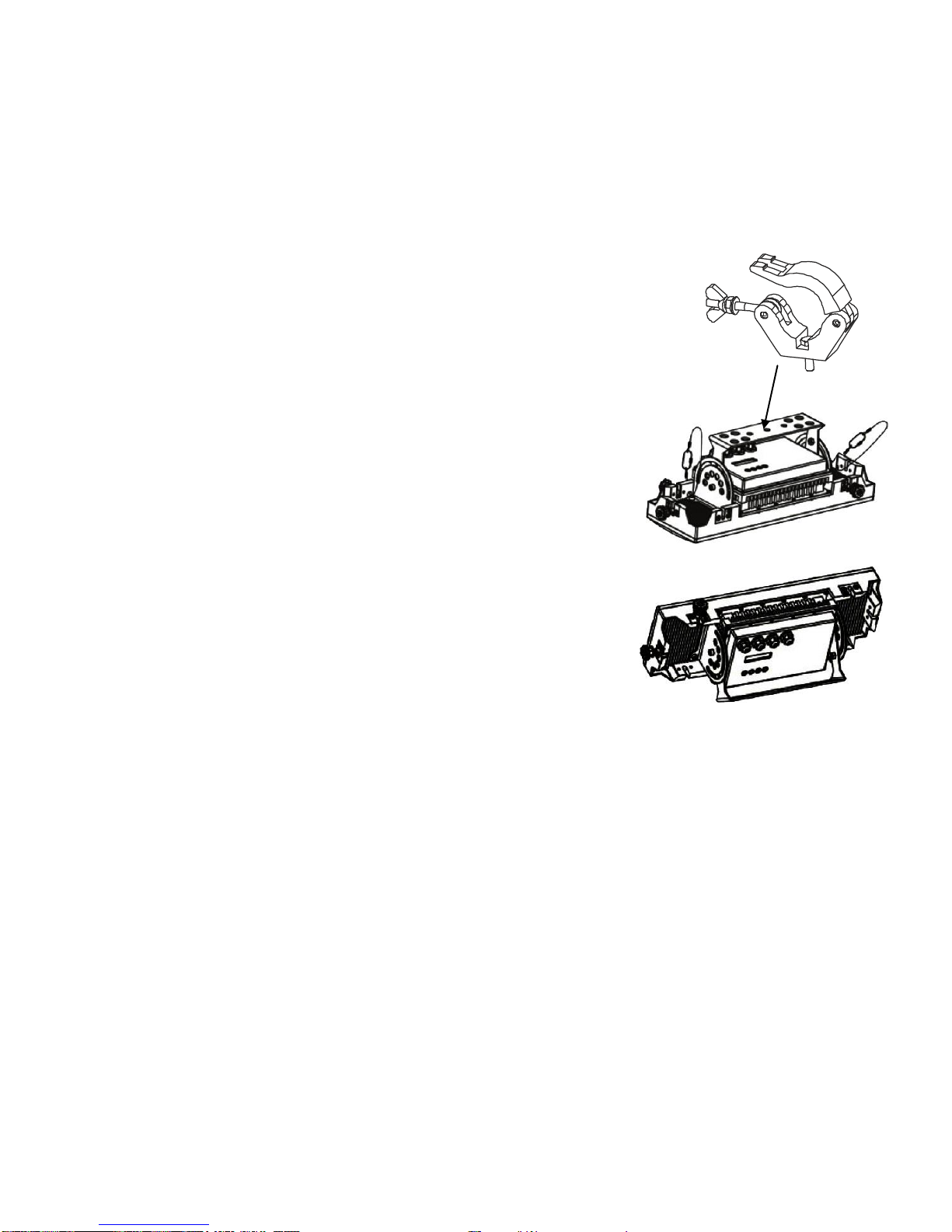
Blow-out Diagram: Parts/Assembly..........................................................................................................................................28
Technical Specifications ...........................................................................................................................................................30

Ilumipod 36X3 IP Optic RGB User Manual 3 5/21/2009 11:44 AM
1. BEFORE YOU BEGIN
What is included
1 x Ilumipanel 36X3 IP Optic RGB
1 x Power cable with plug
1 x IP66 power extension cable
1 x IP66 signal extension cable
1 x DMX input cable adapter
1 x DMX output cable adapter
1 x Warranty Card
1 x User Manual
Unpacking Instructions
Immediately upon receiving a fixture, carefully unpack the carton, check the contents to ensure that
all parts are present, and have been received in good condition. Notify the shipper immediately and
retain packing material for inspection if any parts appear damaged from shipping or the carton itself
shows signs of mishandling. Save the carton and all packing materials. In the event that a fixture
must be returned to the factory, it is important that the fixture be returned in the original factory box
and packing.

Ilumipod 36X3 IP Optic RGB User Manual 4 5/21/2009 11:44 AM
Safety Instructions
Please keep this User Guide for future consultation. If you sell the unit to another user, be sure that
they also receive this instruction booklet.
Always make sure that you are connecting to the proper voltage, and that the line voltage you are
connecting to is not higher than that stated on the decal or rear panel of the fixture.
Always disconnect from power source before servicing or replacing fuse and be sure to replace with
same fuse type.
Secure fixture to fastening device using a safety chain.
Maximum ambient temperature (Ta) is 104°F (40°C). Do not operate fixture at temperatures higher
than this.
In the event of a serious operating problem, stop using the unit immediately. Never try to repair the
unit by yourself. Repairs carried out by unskilled people can lead to damage or malfunction. Please
contact the nearest authorized technical assistance center. Always use the same type spare parts.
Never connect the device to a dimmer pack.
Make sure the power cord is never crimped or damaged.
Never disconnect the power cord by pulling or tugging on the cord.
Avoid direct eye exposure to the light source while it is on.
Do not daisy chain power to more than 8units @ 120V and 16 units @ 230V.
Caution! There are no user serviceable parts inside the unit. Do not open the housing or
attempt any repairs yourself. In the unlikely event your unit may require service,
please contact ILUMINARC™ at: (954) 923-3680.
Caution! After prolonged periods of operation, the fixture chassis may reach high
temperatures. Use caution when handling this fixture.
Note! Please refer to local code and regulation for proper installation of this fixture.
Please read these instructions carefully, which includes important
information about the installation, usage and maintenance of this
product.

Ilumipod 36X3 IP Optic RGB User Manual 5 5/21/2009 11:44 AM
2. INTRODUCTION
Features
3, 4, 9 or 12-channel DMX-512 LED bank system (with ID addressing)
Operating modes
3-channel: RGB control
4-channel: RGB, dimmer
9-channel: RGB, ID, dim, macro, strobe, automatic, custom, DMX modes
9-channel: RGB of 3 separate sections
12-channel: RGB, CMY, ID, dim, macro, strobe, automatic, custom, DMX modes
Blackout/static/dimmer/strobe
Color macros for individual pod control
RGB color mixing with or without DMX controller
Automatic DMX addressing system (ADAS)
Remote addressing system (RAS)
Additional Features
High-power, 1W (350mA) LEDs
Ingress Protection: IP66
Interlock multiple units to create blinder, wall or strip light effects
Additional power output: max 12 units @ 120V
LCD display with password protection

Ilumipod 36X3 IP Optic RGB User Manual 6 5/21/2009 11:44 AM
DMX Channel Summary
The Ilumipanel 36X3 IP Optic RGB has a total of 5 DMX channel configurations, referred to as “Personalities” in this
manual and in the fixture onboard control board. The 5 personalities are [STAGE 1, STAGE2, PIXEL, ARC1, ARC 1+D].
Each of the different personalities can be accessed from the control panel. Please see section on “Control Panel
Functions” on a description on how to accomplish this.
[STAGE 1] DMX MODE 1
CHANNEL
DESCRIPTION
1
Red
2
Green
3
Blue
4
Yellow
5
Cyan
6
Magenta
7
White
8
Strobe
9
Mode Selection
Color-cycle Mode
245 <> 255 : DMX Mode 2
10
ID Address Selection
11
Module Selection
12
Effect Macro
[STAGE 1] DMX MODE 2
CHANNEL
DESCRIPTION
1
Module #1
2
Module #2
3
Module #3
4
No Function
5
6
7
8
Strobe
9
Mode Selection
0 <> 244 : DMX Mode 1
10
ID Address Selection
11
No Function
12
[STAGE 2] DMX MODE 1
CHANNEL
DESCRIPTION
1
Dimmer
2
Red
3
Green
4
Blue
5
Color Macro Selection
6
Strobe
7
Mode Selection
Color-cycle Mode
245 <> 255 : DMX Mode 2
8
ID Addressing
9
Module Selection
Speed Control of CH7 {Color Cycle Mode}
10
Effect Macro

Ilumipod 36X3 IP Optic RGB User Manual 7 5/21/2009 11:44 AM
\
[STAGE 2] DMX MODE 2
CHANNEL
DESCRIPTION
1
Module #1
2
Module #2
3
Module #3
4
No Function
5
6
Strobe
7
Mode Selection
0 <> 244 : DMX Mode 1
0245<> 255 : DMX Mode 2
8
ID Addressing
9
No Function
10
[PIXEL]
CHANNEL
DESCRIPTION
1
Block 1Red
2
Block 1 Green
3
Block 1 Blue
4
Block 2 Red
5
Block 2 Green
6
Block 2 Blue
7
Block 3 Red
8
Block 3 Green
9
Block 3 Blue
[ARC 1]
CHANNEL
DESCRIPTION
1
Red
2
Green
3
Blue
[ARC 1+D]
CHANNEL
DESCRIPTION
1
Dimmer
2
Red
3
Green
4
Blue

Ilumipod 36X3 IP Optic RGB User Manual 8 5/21/2009 11:44 AM
Product Overview
Power Link Out
DMX in
Power in
Power out
DMX out
Safety
attachment

Ilumipod 36X3 IP Optic RGB User Manual 9 5/21/2009 11:44 AM
3. SETUP
AC Power
This fixture has an auto-switching switch-mode power supply that can accommodate a wide range of
input voltages. The only thing necessary to do before powering on the unit is to make sure the line
voltage you are applying is within the range of accepted voltages. This fixture will accommodate
between 100V and 240V AC 50/60 Hz. All fixtures must be powered directly off a switched circuit and
cannot be run off a rheostat (variable resistor) or dimmer circuit, even if the rheostat or dimmer
channel is used solely for a 0% to 100% switch.
This fixture is designed for power linking from one Ilumipanel 36X3 IP Optic RGB to another
Ilumipanel 36X3 IP Optic RGB fixture. Each fixture ships with IP66 proprietary power input cables.
Each fixture ships with a power adapter to male Edison connector.
Warning! All fixtures must be connected to circuits with a suitable Earth Ground.
Depending on the application, the lighting fixture may require a different connector. Please refer to
the below wire color code if installing a new connector.
Wire
Connection
Brown
AC Live
Blue
AC Neutral
Green/Yellow
AC Ground
Connection
Pin
AC Live
1
AC Neutral
2
Ground(Earth)
3

Ilumipod 36X3 IP Optic RGB User Manual 10 5/21/2009 11:44 AM
Note!
Clamp is sold separately.
Mounting
Orientation This fixture may be mounted in any safe position.
Rigging The fixture includes a mounting yoke to which a
rigging clamp can be attached. You must supply your
own clamp and make sure the clamp is capable of
supporting the weight of this fixture. It is
recommended to use at least 2 mounting points per
fixture.
1. Block access below the work area and use suitable and
stable platform when installing or servicing fixture.
2. Safety cables must always be used, utilizing the
provided safety attachment points. The safety cable
must be capable of holding 10 times the weight of the
fixture.
3. Verify the structure can hold 10 times the weight of all
to-be installed fixtures.

Ilumipod 36X3 IP Optic RGB User Manual 11 5/21/2009 11:44 AM
Power Link Out
The interlocking
connectors provide an
easy, fast, and secure
method for stacking
units vertically and
horizontally.
Ilumipanel 36X3 IP Optic RGB stacked for use as a large wash array
Stacking
The Ilumipanel 36X3 IP Optic RGB can be stacked vertically and horizontally to create a large flood array.
Stack them horizontally to create a high power linear wash effect.

Ilumipod 36X3 IP Optic RGB User Manual 12 5/21/2009 11:44 AM
Fixture Linking
You will need a serial data link to run light shows of one or more fixtures using a DMX-512 controller
or to run synchronized shows on two or more fixtures set to a master/slave operating mode. The
combined number of channels required by all the fixtures on a serial data link determines the number
of fixtures the data link can support.
Important: Fixtures on a serial data link must be daisy chained in one single line. To comply with the EIA-485
standard no more than 32 devices should be connected on one data link. Connecting more than 32
fixtures on one serial data link without the use of a DMX optically-isolated splitter may result in
deterioration of the digital DMX signal.
Maximum recommended serial data link distance: 500 meters (1640 ft.)
Maximum recommended number of fixtures on a serial data link: 32 fixtures
Data Cabling
To link fixtures together you must obtain data cables. If you choose to create your own cable please
use data-grade cables that can carry a high quality signal and are less prone to electromagnetic
interference.
DMX DATA CABLE
Use a Belden© 9841 or equivalent cable which meets the specifications for EIA RS-485 applications.
Standard microphone cables cannot transmit DMX data reliably over long distances. The cable will
have the following characteristics:
2-conductor twisted pair plus a shield
Maximum capacitance between conductors –30 pF/ft.
Maximum capacitance between conductor and shield –55 pF/ft.
Maximum resistance of 20 ohms / 1000 ft.
Nominal impedance 100 –140 ohms
CABLE CONNECTORS
Cabling must have a male XLR connector on one end and a female XLR connector on the other end.
CAUTION Do not allow contact between the common and the fixture’s chassis ground. Grounding the common can
cause a ground loop, and your fixture may perform erratically. Test cables with an ohm meter to verify
correct polarity and to make sure the pins are not grounded or shorted to the shield or each other.
COMMON
DMX +
DMX -
INPUT
OUTPUT
1
3
2
1
3
2
1
3
2
Resistance 120
ohm 1/4w between
pin 2 (DMX -) and
pin 3 (DMX +) of
the last fixture.
Termination reduces signal errors. To
avoid signal transmission problems
and interference, it is always
advisable to connect a DMX signal
terminator.
DMX c
o
n
n
e
c
t
o
r
c
o
n
f
i
g
u
r
a
t
i
o
n

Ilumipod 36X3 IP Optic RGB User Manual 13 5/21/2009 11:44 AM
This drawing provides a
general illustration of the
DMX Input/Output panel of
a lighting fixture.
Universal DMX Controller
Continue the link
Often, the setup for Master-Slave
and Standalone operation requires
that the first fixture in the chain be
initialized for this purpose via
settings in the control panel.
Secondarily, the fixtures that follow
may also require a slave setting.
Please consult the “Operating
Instructions” section in this manual
for complete instructions for this
type of setup and configuration.
Master
Slave
Slave
3-PIN TO 5-PIN CONVERSION CHART
Note! If you use a controller with a 5 pin DMX output connector, you will need to use a 5 pin to 3 pin adapter.
The chart below details a proper cable conversion:
3PIN TO 5PIN CONVERSION CHART
Conductor
3 Pin Female (output)
5 Pin Male (Input)
Ground/Shield
Pin 1
Pin 1
Data ( - ) signal
Pin 2
Pin 2
Data ( + ) signal
Pin 3
Pin 3
Do not use
Pin 4
Do not use
Pin 5
Setting up a DMX Serial Data
Link
1. Connect the (male) 3 pin connector side of
the DMX cable to the output (female) 3 pin
connector of the controller.
2. Connect the end of the cable coming from
the controller which will have a (female) 3
pin connector to the input connector of the
next fixture consisting of a (male) 3 pin
connector.
3. Then, proceed to connect from the output
as stated above to the input of the following
fixture and so on.
Master/Slave Fixture Linking
1. Connect the (male) 3 pin connector side of the DMX cable to the output (female) 3 pin connector
of the first fixture.
2. Connect the end of the cable coming from the first fixture which will have a (female) 3 pin
connector to the input connector of the next fixture consisting of a (male) 3 pin connector. Then,
proceed to connect from the output as stated above to the input of the following fixture and so on.

Ilumipanel 36X3 IP Optic RGB User Manual 14 2009-05-21 11:44 AM
DMX Address: 001
ID Address: 01
DMX Address: 001
ID Address: 02
DMX Address: 001
ID Address: 03
DMX Address: 013
ID Address: 01
DMX Address: 013
ID Address: 02
DMX Address: 013
ID Address: 03
DMX 512 Controller
The figure above shows a simple DMX layout which has used three units at each
DMX address. The three units have different ID addresses which allows the user to
collectively control the whole group of units at that DMX address by setting Channel
11 to 0, or to control each unit independently by first selecting the DMX address and
then by using Channel 11 to locate the target ID address. (Note that when using ID
addresses it is also possible to activate ADAS which allows for even more option with
DMX addressing and control.
4. OPERATING INSTRUCTIONS
Control Options
The Ilumipanel 36X3 IP Optic RGB is addressable in the DMX range of 001 to 512. In its simplest
control form, this allows for the control of up to 42 fixtures in the 12-channel “STAG”personality;
however, a secondary ID address system exists for use in a limited DMX universe and architectural
environments. The ID address system allows the user to assign up to 66 fixtures within the same
DMX address; in effect, multiplying the control of fixtures within a single universe to 2,772 fixtures.
The fixture’s ID address system is accessed using DMX channel 11 [STAGE 1]. Consideration must
be placed when programming live performances or cues that need to trigger on demand or on a time
line. So, to remain within one second execution time, program no greater than 10 fixtures on ID
addressing per DMX channel.
DMX-512 control without ID address
The Ilumipanel 36X3 IP Optic RGB operates on 12 channels of DMX (“STAGE 1” personality).
Address each fixture in increments of 9 channels. (I.e. 1,13,25,37, etc…) To save time you can use
the same DMX address for each fixture. All fixtures will then respond simultaneously to control. You
may also group your fixtures and address those groups alike for faster programming and control.
1. Access the control panel function by pressing the (MENU) button until the {RUN MODE} is
displayed.
2. Press (SET) and use the (UP/DOWN) buttons to select {DMX} function.
3. Then, Press (MENU) button until {DMX512 ADDRESS} is displayed.
4. Pres the (SET) button.
6. Use the (UP/DOWN) buttons to increase or decrease channels between 001 and 512.
7. Press the (SET) button to confirm action. Then press (MENU) to exit.
Deactivate ID addressing in each fixture by setting panel function {ID ON/OFF} to OFF.
{MENU} {SETTINGS} {ID ON/OFF} [OFF]
Notes: If ID addressing is not deactivated in the fixture’s control panel function, unintended results may occur if
values are present in channel 10. Make sure values on channel 11 are set to “0”.
DMX-512 addressing with ID address
1. Follow instructions 1 ~ 4 for DMX512 addressing.
2. Activate ID addressing in each fixture by setting panel function {ID ON/OFF} to ON.
{MENU} {Settings) {ID ON/OFF} [ON]
3. For every DMX512 starting address the user can set 66 separate ID addresses.
4. Set ID addresses in each fixture by setting panel function {ID address} to incremental values.
(I.e. 1,2,3,4,5,6,etc…)
{MENU} {Settings} {ID address} [01 ~ 66]
5. ID addresses are accessible using Channel 11 [STAG].

Ilumipanel 36X3 IP Optic RGB User Manual 15 2009-05-21 11:44 AM
MENU
UP
DOWN
SET
Setting the DMX address
Each fixture requires a "start address" from 1 to 512. A fixture requiring one or more channels for
control begins to read the data on the channel indicated by the start address. For example, a fixture
that occupies or uses 7 channels of DMX and was addressed to start on DMX channel 100, would
read data from channels: 100, 101, 102, 103, 104, 105 and 106. Choose start addresses so that the
channels used do not overlap and note the start address selected for future reference. The Ilumipanel
36X3 IP Optic RGB uses up to 12 channels of DMX. If this is your first time using DMX, we
recommend reading the DMX Primer in the Appendix Section.
Control Panel Functions
All fixture functions and settings are accessible via the built-in control panel interface.
BUTTON
FUNCTION
MENU
Exits from the current menu or function
SET
Enables the currently displayed menu or sets the currently selected value in to the
selected function
UP
Navigates upwards through the menu list and increases the numeric value when in a
function
DOWN
Navigates downwards through the menu list and decreases the numeric value when
in a function

Ilumipanel 36X3 IP Optic RGB User Manual 16 2009-05-21 11:44 AM
Menu Map
MAIN FUNCTION
SUB-FUNCTION
SELECTION
INSTRUCTION
Static color
Dimmer
000 ~ 255*
(0 ~ 100%)
*Strobe range
is 0 ~ 20
User can combine Red, Green and Blue to
generate a custom color
Select strobing frequency between 0 and
20Hz
Red
Green
Blue
Color Macros
Strobe
DMX512
001 ~ 512
512 addressable DMX channels
Personality
Stage 1
12 channel mode
Stage 2
10 channel mode
Pixel
9-channel RGB control for each module
Arc 1
3 channel RGB mode
Arc 1+D
4 channel RGB+D mode
Run Mode
DMX
Allow DMX control
CON
Optional controller
Auto program
1
Choose from 8 Automatic run programs
2
3
4
5
6
7
8
Settings
ID address
01 ~ 66
Assigns the ID address to a fixture
ID ON/OFF
On ~ Off
Either enables or disables ID addressing
ADAS faders no
01 ~ 244
Sets the number of ADAS channels for use
when automating DMX channel assignment
ADAS ON/OFF
On ~ Off
Enables the Automatic DMX512
Addressing System
ADAS copy
On ~ Off
When activated the DMX512 address
assigned by the ADAS will become
permanent on the fixture
Factory settings
Reset confirm
Resets fixture to factory default settings
Dimmer start
[001] or [005]
Password
ON/OFF
On ~ Off
When password is set to on the control
panel will ask for a password each time the
control panel is accessed
Set Password
[▲▼▲▼▲▲▼▼]
Use UP and DOWN buttons to set and
press SET to confirm
Note! If you forget the password use the
following factory password:
UP, DOWN, UP, DOWN, UP, UP, DOWN,
DOWN
Manual Power ON/OFF
The Ilumipanel 36X3 IP Optic RGB can be turned on and off using the control panel.
POWER
ACTION
Turn OFF
When {MENU} is displayed in the LCD panel, hold down the (EXIT) button for 3
seconds to turn off the fixture.
Turn ON
Hold the {EXIT} button for 3 seconds to turn power on.

Ilumipanel 36X3 IP Optic RGB User Manual 17 2009-05-21 11:44 AM
DMX512 Channel Values
The Ilumipanel 36X3 Optic RGB has 5 DMX512 channel configurations [STAGE 1, STAGE 2, PIXEL,
ARC1, ARC1+D].
Both [STAGE 1] & [STAGE 2] have 2 DMX modes {DMX MODE1} & {DMX MODE 2}. Channel 9 is
used to switch between modes in STAGE1, and Channel 7 is used in STAGE 2.
STAGE 1 [DMX CONTROL MODE 1]
CHANNEL
VALUE
FUNCTION
1
000 004
005 255
Red
No Function
0 100%
2
000 004
005 255
Green
No Function
0 100%
3
000 004
005 255
Blue
No Function
0 100%
4
000 004
005 255
Yellow
No Function
0 100%
5
000 004
005 255
Cyan
No Function
0 100%
6
000 004
005 255
Magenta
No Function
0 100%
7
000 004
005 255
White
No Function
0 100%
8
000 004
005 255
Strobe
No Function
0 20Hz
9
000 004
005 034
035 064
065 094
095 124
125 154
155 184
185 214
215 244
245 255
Mode Selection
No Function
Color-Cycle Mode 1
Color-Cycle Mode 2
Color-Cycle Mode 3
Color-Cycle Mode 4
Color-Cycle Mode 5
Color-Cycle Mode 6
Color-Cycle Mode 7
Color-Cycle Mode 8
DMX MODE 2
Channel 10 (ID address selection)
000 009
010 019
020 029
030 039
040 049
050 059
060 069
070 079
080 089
090 099
100 109
110 119
120 129
130 139
140 149
150 159
160 169
170 179
180 189
190 199
200 209
210
211
All IDs
ID 1
ID 2
ID 3
ID 4
ID 5
ID 6
ID 7
ID 8
ID 9
ID 10
ID 11
ID 12
ID 13
ID 14
ID 15
ID 16
ID 17
ID 18
ID 19
ID 20
ID 21
ID 22
212
213
214
215
216
217
218
219
220
221
222
223
224
225
226
227
228
229
230
231
232
233
234
ID 23
ID 24
ID 25
ID 26
ID 27
ID 28
ID 29
ID 30
ID 31
ID 32
ID 33
ID 34
ID 35
ID 36
ID 37
ID 38
ID 39
ID 40
ID 41
ID 42
ID 43
ID 44
ID 45
235
236
237
238
239
240
241
242
243
244
245
246
247
248
249
250
251
252
253
254
255
ID 46
ID 47
ID 48
ID 49
ID 50
ID 51
ID 52
ID 53
ID 54
ID 55
ID 56
ID 57
ID 58
ID 59
ID 60
ID 61
ID 62
ID 63
ID 64
ID 65
ID 66

Ilumipanel 36X3 IP Optic RGB User Manual 18 2009-05-21 11:44 AM
CHANNEL
VALUE
FUNCTION
11
000 004
005 034
035 064
065 094
095 124
125 154
155 184
185 214
215 255
Module Selection
#1=ON, #2=ON, #3=ON
#1=ON
#2=ON
#3=ON
#1=ON, #2=ON
#2=ON, #3=ON
#1=ON, #3=ON
#1=ON, #2=ON, #3=ON
#1=OFF, #2=OFF, #3=OFF
000 255
Speed control of Channel 9 Color-Cycle Mode 4
12
000 004
005 008
009 013
014 018
019 023
024 028
029 033
034 038
039 043
044 048
049 053
054 058
059 063
064 068
069 073
074 078
079 083
084 088
089 093
094 098
099 103
104 108
109 113
114 118
119 123
124 128
129 133
134 138
139 143
144 148
149 153
154 158
159 163
164 168
169 173
174 178
179 183
184 188
189 193
194 198
199 203
204 208
209 213
214 218
219 223
224 228
229 233
234 238
239 243
244 248
249 255
Effect Macro
No Function
Macro 01
Macro 02
Macro 03
Macro 04
Macro 05
Macro 06
Macro 07
Macro 08
Macro 09
Macro 10
Macro 11
Macro 12
Macro 13
Macro 14
Macro 15
Macro 16
Macro 17
Macro 18
Macro 19
Macro 20
Macro 21
Macro 22
Macro 23
Macro 24
Macro 25
Macro 26
Macro 27
Macro 28
Macro 29
Macro 30
Macro 31
Macro 32
Macro 33
Macro 34
Macro 35
Macro 36
Macro 37
Macro 38
Macro 39
Macro 40
Macro 41
Macro 42
Macro 43
Macro 44
Macro 45
Macro 46
Macro 47
Macro 48
Macro 49
Macro 50

Ilumipanel 36X3 IP Optic RGB User Manual 19 2009-05-21 11:44 AM
STAGE 1 [DMX CONTROL MODE 2]
CHANNEL
VALUE
FUNCTION
1
000 004
005 034
035 064
065 094
095 124
125 154
155 184
185 255
Module 1
No Function
Red
Green
Blue
Yellow
Cyan
Magenta
Pink-White
2
000 004
005 034
035 064
065 094
095 124
125 154
155 184
185 255
Module 2
No Function
Red
Green
Blue
Yellow
Cyan
Magenta
Pink-White
3
000 004
005 034
035 064
065 094
095 124
125 154
155 184
185 255
Module 3
No Function
Red
Green
Blue
Yellow
Cyan
Magenta
Pink-White
4
No Function
5
6
7
8
000 004
005 255
Strobe
No Function
0 20Hz
9
000 244
245 255
Mode Selection
DMX MODE 1 (only when channels 1-7 = 0)
DMX MODE 2
10
ID Address
Selection
See Channel 10 (ID address selection) on
page 20 under DMX Control Mode 1
11
No Function
12

Ilumipanel 36X3 IP Optic RGB User Manual 20 2009-05-21 11:44 AM
STAGE 2 [DMX CONTROL MODE 1]
CHANNEL
VALUE
FUNCTION
1
000 004
005 255
Dimmer
No Function
0 100%
2
000 004
005 255
Red
No Function
0 100%
3
000 004
005 255
Green
No Function
0 100%
4
000 004
005 255
Blue
No Function
0 100%
5
000 009
010 029
030 039
040 049
050 069
070 079
080 089
090 109
110 119
120 129
130 149
150 159
160 169
170 189
190 199
200 219
220 229
230 249
250 255
Color Macros
No Function
Red (100%)
Red (85%) + Green (15%)
Red (60%) + Green (40%)
Yellow (100%)
Red (15%) + Green (85%)
Red (40%) + Green (60%)
Green (100%)
Green (85%) + Blue (15%)
Green (60%) + Blue (40%)
Blue (100%)
Blue (85%) + Green (15%)
Blue (60%) + Green (40%)
Cyan (100%)
Green (50%) + Magenta (50%)
Magenta (100%)
Magenta (80%) + Green (20%)
RGB (100%)
White (100%)
6
000 004
005 255
Strobe
No Function
0 20Hz
7
000 004
005 034
035 064
065 094
095 124
125 154
155 184
185 214
215 244
245 255
Mode Selection
No Function
Color-Cycle Mode 1
Color-Cycle Mode 2
Color-Cycle Mode 3
Color-Cycle Mode 4
Color-Cycle Mode 5
Color-Cycle Mode 6
Color-Cycle Mode 7
Color-Cycle Mode 8
DMX MODE 2
Channel 8 (ID address selection)
000 009
010 019
020 029
030 039
040 049
050 059
060 069
070 079
080 089
090 099
100 109
110 119
120 129
130 139
140 149
150 159
160 169
170 179
180 189
190 199
200 209
210
211
All IDs
ID 1
ID 2
ID 3
ID 4
ID 5
ID 6
ID 7
ID 8
ID 9
ID 10
ID 11
ID 12
ID 13
ID 14
ID 15
ID 16
ID 17
ID 18
ID 19
ID 20
ID 21
ID 22
212
213
214
215
216
217
218
219
220
221
222
223
224
225
226
227
228
229
230
231
232
233
234
ID 23
ID 24
ID 25
ID 26
ID 27
ID 28
ID 29
ID 30
ID 31
ID 32
ID 33
ID 34
ID 35
ID 36
ID 37
ID 38
ID 39
ID 40
ID 41
ID 42
ID 43
ID 44
ID 45
235
236
237
238
239
240
241
242
243
244
245
246
247
248
249
250
251
252
253
254
255
ID 46
ID 47
ID 48
ID 49
ID 50
ID 51
ID 52
ID 53
ID 54
ID 55
ID 56
ID 57
ID 58
ID 59
ID 60
ID 61
ID 62
ID 63
ID 64
ID 65
ID 66
This manual suits for next models
1
Table of contents
Other Iluminarc Light Fixture manuals