Iluminarc Ilumipod Inground 36 IP VW User manual

Ilumipod Inground IP Series
User Manual
•Ilumipod Inground 36 IP VW
•Ilumipod Inground 36 IP RGB
•Ilumipod Inground Tri-12 IP

Edition Notes
Ilumipod Inground IP Series User Manual
Edition Notes
The Ilumipod Inground IP Series User Manual Rev. 03 covers the description, safety precautions, installation,
programming, operation, and maintenance of the Ilumipod Inground 36 IP RGB, Ilumipod Inground 36 IP VW,
and Ilumipod Inground Tri-12 IP products. ILUMINARC®released this edition of the Ilumipod Inground IP Series
User Manual Rev. 03 in April 2014.
Trademarks
The ILUMINARC®logo, the ILUMINARC®name, and all other trademarks in this document related to services
or products by ILUMINARC®are trademarks owned or licensed by ILUMINARC®, its affiliates, or subsidiaries.
Any other product names, logos, brands, company names, or trademark
s featured or referred to within this
document are the property of their respective trademark holders.
Copyright Notice
The entire content of this document, except where applicable and unless otherwise noted, is solely owned by
ILUMINARC®, a wholly owned trademark of CHAUVET & Sons, Inc.
© Copyright 2014 ILUMINARC®
All rights reserved.
Electronically published by ILUMINARC®in the United States of America.
Manual Usage
ILUMINARC®authorizes its customers to download and print this manual for professional information purposes
only. ILUMINARC®expressly prohibits the usage, copy, storage, distribution, modification,
or printing of this
manual or its content for any other purpose without its written consent.
Document Printing
For better results, print this document in color, on letter size paper (8.5 x 11 inches), double sided. If using A4
paper (210 x 297 mm), configure your printer to scale the content of this document to A4 paper.
Intended Audience
Any person in charge of installing, operating, and/or maintaining any of these products should read the Guide
that shipped with it and this manual in their entirety before installing, operating, or maintaining the product.
Disclaimer
ILUMINARC®believes that the information contained in this manual is accurate in
all respects. However,
ILUMINARC®assumes no responsibility for any error or omissions in this document. ILUMINARC®reserves the
right to revise this document and to make changes from time to time in the content hereof without obligation of
ILUMINARC®to notify any person or company of such revision or changes. This does not constitute in any way
a commitment by ILUMINARC®to make such changes. ILUMINARC®may issue a revision of this manual or a
new edition of it to incorporate such changes.
Document Revision
The Ilumipod Inground IP Series User Manual Rev. 03 supersedes all previous versions of this manual. Please
discard any older versions of this manual you may have, whether in printed or electronic format, and replace
them with this version.

Table of Contents
Ilumipod Inground IP Series User Manual (Rev. 03) i
Table of Contents
1. Introduction ...................................................................................................1
What is in the Box ........................................................................................................ 1
Unpacking Instructions................................................................................................. 1
Text Conventions ......................................................................................................... 1
Safety Notes................................................................................................................. 2
Personal Safety...................................................................................................................2
Mounting and Installation.....................................................................................................2
Power and Wiring................................................................................................................2
Operation.............................................................................................................................2
2. Product Description......................................................................................3
Common Features........................................................................................................ 3
Ilumipod Inground 36 IP VW Features.................................................................................3
Ilumipod Inground 36 IP RGB Features...............................................................................3
Ilumipod Inground Tri-12 IP Features..................................................................................3
Product Dimensions ..................................................................................................... 4
3. Installation.....................................................................................................5
Installation Notes.......................................................................................................... 5
Installation Sleeve Orientation.............................................................................................5
Installation Sleeve Setup.....................................................................................................5
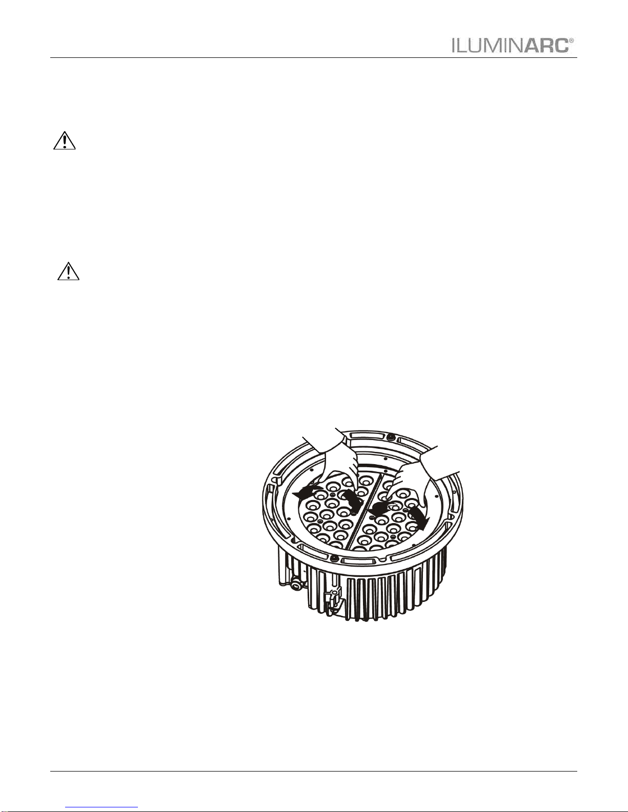
Beam Angle Adjustment......................................................................................................6
AC Power ..................................................................................................................... 7
Input Voltage and Frequency...............................................................................................7
Power Consumption............................................................................................................7
Junction Box Wiring...................................................................................................... 7
Power Wiring.......................................................................................................................7
Signal Wiring .......................................................................................................................8
External Wiring............................................................................................................. 8
Power Distribution ...............................................................................................................8
Signal Distribution................................................................................................................8
Controllers.................................................................................................................... 9
DMX Controller....................................................................................................................9
ILUMICON...........................................................................................................................9
Ilumicode...........................................................................................................................10
4. Operation.....................................................................................................11
Ilumicode.................................................................................................................... 11
Ilumicode Panel Description..............................................................................................11
Menu Map .................................................................................................................. 11
White Functions Menu Map...............................................................................................11
RGB Functions Menu Map ................................................................................................12
Programming.............................................................................................................. 13
DMX Personality................................................................................................................13
DMX Starting Address.......................................................................................................13
Dimmer..............................................................................................................................13
ILUMICON Control ............................................................................................................14
Static Color........................................................................................................................14
Color Calibration................................................................................................................14
Color..................................................................................................................................14
Reset.................................................................................................................................14
DMX Values ............................................................................................................... 15
ARC 1................................................................................................................................15
ARC 1 + D.........................................................................................................................15
ARC FULL.........................................................................................................................15
SPECIAL 1 ........................................................................................................................16

Table of Contents
ii Ilumipod Inground IP Series User Manual (Rev. 03)
VW.....................................................................................................................................16
VW + D..............................................................................................................................16
SOLID................................................................................................................................16
5. Technical Information.................................................................................17
Product Maintenance ................................................................................................. 17
Product Repairs.......................................................................................................... 17
Troubleshooting Guide............................................................................................... 18
Exploded View............................................................................................................ 19
Photometrics .............................................................................................................. 20
Ilumipod Inground 36 IP 15º VW .......................................................................................20
Ilumipod Inground 36 IP 30º VW .......................................................................................21
Ilumipod Inground 36 IP 15º RGB .....................................................................................22
Ilumipod Inground 36 IP 30º RGB .....................................................................................23
Ilumipod Inground Tri-12 IP 16º.........................................................................................24
LED Disclaimer........................................................................................................... 25
LED Life.............................................................................................................................25
LED Binning.......................................................................................................................25
Color Rendering Index (CRI).............................................................................................25
Returns Procedure..................................................................................................... 26
Claims......................................................................................................................... 26
Contact Us.................................................................................................................. 26
Technical Specifications............................................................................................. 27
Ilumipod Inground 36 IP VW..............................................................................................27
Ilumipod Inground 36 IP RGB............................................................................................28
Ilumipod Inground Tri-12 IP...............................................................................................29

Introduction
Ilumipod Inground IP Series User Manual (Rev. 03) 1
1. Introduction
This icon
indicates useful,
although non-
critical information.
This icon
indicates
important
installation or
configuration information.
Failure to comply with this
information may prevent
the product from
functioning correctly.
This icon
indicates critical
installation,
configuration, or operation
information. Failure to
comply with this
information may render
the product partially or
completely inoperative,
damage third-party
equipment, or cause harm
to the user
The term “DMX”
used throughout
this document
refers to the USITT
DMX512-A transmission
protocol.
What is in the Box
•One Ilumipod Inground IP product (36 IP RGB, 36 IP VW, or Tri-12 IP)
•Warranty Card
•Quick Reference Guide
Unpacking Instructions
Immediately upon receiving a product from ILUMINARC®, carefully unpack the carton.
Check the contents of the box to ensure that all parts are present and that they are in good
condition. If any part appears damaged from shipping, or if the carton shows signs of
mishandling, see the Claims section in the Technical Information chapter.
Text Conventions
Convention Meaning
1~512
A range of values in the text
50/60
A set of mutually exclusive values in the text
“ILUMICON UM”
The name of another publication or manual
<SET>
A button on the product’s control panel
SETTINGS
A product function or a menu option
MENU > SETTINGS
A sequence of menu options
1~10
A range of menu values from which to choose in a menu
Yes/No
A set of two mutually exclusive menu options in a menu
ON
A unique value to enter or select in a menu

Introduction
2 Ilumipod Inground IP Series User Manual (Rev. 03)
There are no
user serviceable
parts inside this
product. Any reference to
servicing it you may find
from now on in this User
Manual will only apply to
properly ILUMINARC®
authorized technicians.
Do not open the housing
or attempt any repairs
unless you are certified to
do so.
Please refer to all
applicable local
codes and
regulations for the proper
installation of this product.
Keep this manual
for future
consultation. If
you sell this product to
another user, make sure
that they also receive this
manual.
In the unlikely
event that your
Ilumipod
Inground IP product may
require service, please
contact ILUMINARC®
Technical Support.
Safety Notes
Please read all the following safety notes carefully because they include important information
on how to install, use, and maintain this product safely.
Personal Safety
•Avoid direct eye exposure to the light source while the product is on.
•Always disconnect the Ilumipod Inground IP product from its power source before
servicing.
•Always connect the Ilumipod Inground IP product to a grounded circuit to avoid the risk
of electrocution.
Mounting and Installation
•The Ilumipod Inground IP products are for outdoor use and they can work while
submerged in up to 1 m of water (IP67). However, do not submerge it deeper than 1m
for more than (30) thirty minutes.
•Observe the installation instructions regarding drainage to ensure that the water level is
never higher than 1 m for more than (30) thirty minutes to comply with the IP67 rating.
Power and Wiring
•Always make sure that you are connecting this product to the proper voltage, as per the
specifications in this manual or on the product’s sticker.
•Never connect this product to a dimmer pack.
•Make sure that the power cable is not cracked, crimped, or damaged.
•Make sure that the sealed cover is properly adjusted to avoid water entering the unit.
Operation
•The maximum ambient temperature (Ta) is 113 °F (45 °C). Do not operate this product
at a higher temperature.
•In case of a serious operating problem, stop using this product immediately!

Product Description
Ilumipod Inground IP Series User Manual (Rev. 03) 3
2. Product Description
Other than their
LED configuration
and programming
features, these
three products share the
same dimensions, as well
as the installation, wiring,
and troubleshooting
procedures.
The lenses in
these three
products are non-
changeable.
Therefore, make sure to
use the right product
order code for the desired
lens angle.
The Ilumipod Inground IP Series encompasses three products, Ilumipod Inground 36 IP RGB,
Ilumipod Inground 36 IP VW, and Ilumipod Inground Tri-12 IP.
Common Features
•Remotely addressable DMX-512 LED inground wash light
•IP67 ingress protection
•IP67 stainless steel gland nuts for cable entry
•Adjustable module angle
•Cast aluminum and stainless steel housing
•Impact resistant tempered glass lens cover (drive-over rated)
•Polished stainless steel mounting ring
•Ilumicode compatible
Ilumipod Inground 36 IP VW Features
•Operating modes:
1-channel: Dimmer
2-channel: Warm white, cool white
3-channel: Warm white, cool white, dimmer
•High power 1 W (750 mA) Warm White and Cool White LEDs
•Installed (non-changeable) optical system:
15°lenses - Product order code: 11036010
30º lenses - Product order code: 11036008
Ilumipod Inground 36 IP RGB Features
•Operating modes:
1-channel: Dimmer
3-channel: RGB control
4-channel: RGB, dimmer
6-channel: RGB per module
7-channel: RGB, dimmer, macro, strobe, dimming speed
•High power 1 W (750 mA) Red, Green, and, Blue LEDs
•Blackout/static/dimmer/strobe/pulse
•Installed (non-changeable) optical system:
15°lenses - Product order code: 11036009
30º lenses - Product order code: 11036007
Ilumipod Inground Tri-12 IP Features
•Operating modes:
1-channel: Dimmer
3-channel: RGB control
4-channel: RGB, dimmer
6-channel: RGB per module
7-channel: RGB, dimmer, macro, strobe, dimming speed
•High power 3 W (1,050 mA) tri-color LEDs
•Blackout/static/dimmer/strobe/pulse
•Installed (non-changeable) optical system:
16
°
lenses - Product order code: 11012001

Product Description
4 Ilumipod Inground IP Series User Manual (Rev. 03)
Product Dimensions
(All Ilumipod Inground IP Series models)

Installation
Ilumipod Inground IP Series User Manual (Rev. 03) 5
3. Installation
Always keep the
power cables
away from the
signal cables by
running them in different
conduits and using
separate distribution
boxes.
The Ilumipod
Inground IP
products can
support a distributed load
of up to 3,000 kg (6,614
lbs) when properly
installed.
Installation Notes
The Ilumipod Inground IP products consist of two parts, the product housing and the concrete
installation sleeve. The product housing is IP67 rated, but the installation sleeve is not. Please
pay close attention to the installation instructions for the concrete installation sleeve regarding
leveling and drainage.
You will have to run the AC power and signal cables into the concrete installation sleeve and
the product’s housing.
Do not use the product’s junction box to extend the power or signal cables to other units
because it may compromise the IP rating of the junction box. Instead, use individual cables
from the product to the corresponding distribution boxes.
Installation Sleeve Orientation
Orient the installation sleeve to allow the signal cable to enter the sleeve using one of the four
cable inlets and the power cable to use the opposite inlet, as seen in the figure. This will
reduce the stress to the signal and power cables when setting down the product, while keeping
them separated under the product’s housing.
Installation Sleeve Setup
When setting up the installation sleeve, make sure that any water that may have entered it can
drain out of the sleeve on its own. Locate the installation sleeve above the normal drainage
level so the product is never under more than 1 m of water (IP67) during heavy rain.
In addition, make sure that the installation sleeve and the stainless steel collar are horizontal
and even with the ground surface. This helps to distribute the load uniformly over the
product’s surface and avoids creating dangerous bumps.

Installation
6 Ilumipod Inground IP Series User Manual (Rev. 03)
Make sure to
disconnect the
power to the
product before opening it.
Be careful when
opening and
closing the
product’s housing as it
may compromise the
product’s IP67 rating.
Beam Angle Adjustment
The Ilumipod Inground IP products have two LED modules each. You can adjust the angle of
each of these modules to spread or narrow the product’s beam. To do so, follow these steps:
1. Loosen the Allen bolts on the stainless steel collar by turning them CCW, not more
than a turn or two, enough to release the aluminum latch from its “locked”
position.
2. Lift the product from the installation sleeve, making sure not to stretch the power
and signal cables.
3. Loosen four of the six nuts that hold the collar to the housing, leaving untouched
any two adjacent nuts.
4. Wait a few seconds for the seal to expand. This lowers the possibility of damaging
the seal.
5. Complete the removal of the two remaining nuts.
6. Remove the stainless steel collar.
7. Carefully, lift and remove the protective glass and the seal attached to it, making
sure not to reverse the glass.
8. Using only your hands, push on the sides of each module to adjust its angle, as
shown in the figure below.
9. Replace the glass and then re-silicone the seal to insure a watertight seal.
10. Replace the stainless steel collar, making sure to align it with the Allen screws and
while keeping the glass surface flush with the collar.
11. Replace all six nuts and adjust them manually until they touch the housing.
12. Tighten the nuts uniformly by alternating between opposite nuts.
13. Reattach the product to the installation sleeve by turning the Allen bolts CW. You
should only need a turn or two to have the stainless steel collar firmly attached.

Installation
Ilumipod Inground IP Series User Manual (Rev. 03) 7
Make sure to
connect the
Ilumipod Inground
IP product to a power line
with the proper voltage
and frequency, as per the
specifications in this
manual or on the
product’s sticker.
The listed
current rating
indicates the
maximum
current draw during
normal operation.
Always connect
the Ilumipod
Inground IP
products to protected
circuits (CB or fuse) with
an appropriate electrical
ground to avoid the risk of
electrocution or fire.
Never connect an
Ilumipod Inground
IP product to a
rheostat (variable resistor)
or dimmer circuit, even if
the rheostat or dimmer
channel serves only as a
0 to 100% switch.
Make sure to use
power and signal
cables with the
indicated outer diameters
to ensure that the
corresponding gland nut
makes full contact with
the cable’s external
insulation. This is required
to keep the product’s IP67
rating when fully adjusted.
AC Power
Input Voltage and Frequency
The products in the Ilumipod Inground IP Series have an auto-ranging power supply with an
input voltage range of 100~240 VAC, 50/60 Hz.
Power Consumption
To determine the power requirements for any of the Ilumipod Inground IP products see the
label affixed to the side of the product. Alternatively, you may refer to the corresponding
specifications chart in the Technical Information chapter of this manual.
Junction Box Wiring
The Ilumipod Inground IP products have an IP67 rated junction box where the power and signal
cables come into the unit. The cables access the junction box through individual (signal and
power) IP67 rated stainless steel gland nuts.
Make sure that the junction seal is clean before placing the cover back on. In addition, tighten
the gland nuts and the junction cover to prevent water from entering the junction box and
causing a short.
The figure below shows the connections in the junction box.
Power Wiring
To provide AC power for any of the Ilumipod Inground
IP products, you must run a single SJTW rated 3-
conductor cable (AWG18/3, 6~8 mm external diameter)
from the power distribution box into the installation
sleeve and the product’s junction box.
Strip the end of the AC power cable that will connect to
the junction box as indicated in the figure on the right.
Connection Wire (US) Wire (Europe)
Live
Black
Brown
Neutral
White
Blue
Ground
Green/Yellow
Green/Yellow
AC Power Input Wiring

Installation
8 Ilumipod Inground IP Series User Manual (Rev. 03)
The signal cable
must match or
exceed the
electrical
characteristics of the
Belden® 9841 cable for
EIA RS-485 applications.
If you choose to
bury the power or
signal distribution
boxes, make sure that
they are IP67 rated.
Signal Wiring
To provide signal for any of the Ilumipod Inground IP products, you must run a single, IP67
rated DMX signal cable (shielded, 2-conductor, AWG24/2, 6.5 mm external diameter 120
ohm typical impedance) from the signal distribution box into the installation sleeve and the
product’s junction box.
External Wiring
You must run AC power and signal wires from the respective AC and signal distribution
boxes into each of the Ilumipod Inground IP products.
Power Distribution
Connect the bare-ended power cable from the product to a power distribution box as indicated
below.
Signal Distribution
Connect the bare-ended signal cable from the product to a signal distribution box as indicated
below.
(Black)

Installation
Ilumipod Inground IP Series User Manual (Rev. 03) 9
If you have not
configured the
DMX starting
address and DMX
mode for each product,
they will all use their
default values. This
means that all products
will operate in unison.
Refer to the
Operation chapter
to learn how to
enable the
Ilumipod Inground IP
products to operate with
the ILUMICON controller.
Controllers
The products in the Ilumipod Inground IP Series can operate with a standard DMX controller,
the ILUMICON controller, or the Ilumicode controller. The sections below will show you how
to connect these products to the corresponding controllers. The instructions to operate these
products with each of the above controllers are in the Operation chapter of this manual.
DMX Controller
The Ilumipod Inground IP products can work with a standard DMX controller. The channel
assignments will depend on the chosen personality (see the corresponding Menu Map on
pages 11 and 12) and the DMX address assigned to each product (see Programming on page
13).
The figure below illustrates how to connect the DMX controller to the Ilumipod Inground IP
products.
ILUMICON
The Ilumipod Inground IP Tri and RGB products can also work with the ILUMICON
controller instead of a standard DMX controller. Please refer to the ILUMICON User Manual
to learn how to use this controller with the Ilumipod Inground IP products.
The figure below illustrates how to connect the ILUMICON controller to the Ilumipod
Inground IP Tri and RGB products.

Installation
10 Ilumipod Inground IP Series User Manual (Rev. 03)
To assign
individual DMX
addresses to
each product, you
must connect the
Ilumicode controller to
each product, individually.
ILUMINARC®
suggests that you
connect no more
than 20 products
in this mode and keep the
total distance to less than
60 m (197 ft). Otherwise,
you might need to use an
optically isolated signal
amplifier.
Ilumicode
The diagram below shows how to connect the Ilumicode to this product.
Note that this connection will control multiple products at the same time, all having the same
DMX address.

Operation
Ilumipod Inground IP Series User Manual (Rev. 03) 11
4. Operation
When you scroll
through the
menu options,
you will see
many of them that do not
correspond with this menu
map. Skip them, as they
do not work with the
White output products.
If you scroll after
STRB, you will
see the
RED,
GREN, BLUE,
and
AMBE
colors. Just
skip them as they do not
work with the VW
products.
Ilumicode
The products in
the Ilumipod Inground IP Series lack a control panel. Therefore, they need an
external controller, the Ilumicode device, to change their configuration.
Ilumicode Panel Description
Menu Map
The products
in the Ilumipod Inground IP Series have distinct menu maps based on the colors they
produce, whether RGB or White. The Ilumicode controller presents
the functions for both types of
products.
White Functions Menu Map
(Ilumipod Inground 36 IP VW)
This menu map shows you which parameters of the Ilumicode controller correspond to the
Ilumipod Inground 36 IP VW product.
Main Level Programming Levels Description
DMX 001~512 N/A Sets the DMX starting address
PERSON
VW
N/A
3-channel: SpectraWhite control
VW+D
4-channel: SpectraWhite control + dimmer
SOLID 1-channel: dimmer
DIMMER
OFF
N/A
Dimmer work in linear mode
DIM 1
Dimmer works in non-linear mode, from fast to
slow.
DIM 2
DIM 3
DIM 4
STATIC COOL 0~255 Configures the static color and effect
WARM
Button
Function
<MENU>
Exits from the current menu or function
<ENTER>
Enables the currently displayed menu or sets the
currently selected value into the selected function
<UP>
Navigates upwards through the menu list and increases
the numeric value when in a function
<DOWN>
Navigates downwards through the menu list and
decreases the numeric value when in a function
<POWER>
Turns the unit on. The unit will turn off automatically
after 30 seconds of inactivity.

Operation
12 Ilumipod Inground IP Series User Manual (Rev. 03)
When you scroll
through the
menu options,
you will see
many of them that do not
correspond with this menu
map. Skip them, as they
do not work with the RGB
only output products.
If you scroll after
STRB, you will
see the AMBE,
COOL and
WARM colors. Just skip
them as they do not work
with the RGB products.
RGB Functions Menu Map
(Ilumipod Inground 36 IP RGB and Ilumipod Inground Tri-12 IP)
Main Level Programming Levels Description
DMX 001~512 N/A Sets the DMX starting address
PERSON
ARC 1
N/A
3-channel: RGB control
ARC 1 + D
4-channel: RGB control + dimmer
ARC FULL
7-channel: RGB control, dimmer, color macro, strobe,
dimmer speed
REMOTE
Allows using the ILUMICON unit
SPECIAL1
6-channel: RGB control per module
SOLID
1-channel: dimmer
CALIB
WHITE (1~11) RED
GREN
BLUE 0~255
Determines the white balance for the color macros
RGBTOW Determines the white balance when RGBTOW is
active
DIMMER
OFF
N/A
Dimmer work in linear mode
DIM 1
Dimmer works in non-linear mode, from fast to slow.
DIM 2
DIM 3
DIM 4
STATIC
RED
0~255 Configures the static color and effect
GREN
BLUE
STRB
SETTINGS COLOR
OFF Maximum output, unbalanced white
RGBTOW White output is as per
CALIB > RGBTOW
settings
UC
Output matches that of product’s previous versions
RESET
NO/YES
Resets unit to factory default settings

Operation
Ilumipod Inground IP Series User Manual (Rev. 03) 13
Make sure to
press <ENTER>
after selecting an
option. Otherwise, the
product will not save the
new setting. In this case,
the Ilumicode’s display
will show “SEND…”
The DMX Starting
Address setting
works with all but
the REMOTE
personality.
Programming
Carry out all the programming procedures indicated below from Ilumicode’s panel. Refer to the
corresponding Menu Map (pages 11 and 12) to learn how the menu options relate to each other
depending on the type of product.
Use <ENTER> and <MENU> to change levels in the Menu Map. This is equivalent to moving
right and left respectively. Use <UP> and <DOWN> to move forward and backwards
respectively within the Menu Map options.
Press <ENTER> to accept the selected value for an option. This will send that value to the
product(s).
DMX Personality
(All Ilumipod Inground IP products)
1. Go to PERSON and select any DMX personality that matches the product with which
you are working (ignore any other options).
36 IP RGB & Tri-12 IP 36 IP VW
ARC1
ARC+D
ARC FULL
SOLID
SOLID
SPECIAL1
VW
VW+D
2. Make sure to arrange the DMX addresses of all products in the current DMX universe
to avoid address overlapping.
DMX Starting Address
(All Ilumipod Inground IP products)
1. Go to DMX.
2. Select a starting DMX address (001~512).
Dimmer
(All Ilumipod Inground IP products)
1. Go to DIMMER.
2. Select a dimmer curve (OFF or DIM1~4).
DIMMER
Description
OFF
Dimmer curve is linear with fader
DIM1
Non-linear (fastest)
DIM2
Non-linear (fast)
DIM3
Non-linear (slow)
DIM4
Non-linear (slowest)

Operation
14 Ilumipod Inground IP Series User Manual (Rev. 03)
Do not connect
any other
controller to the
product(s) when using the
ILUMICON controller.
WHITE 1~11
define the white
color shown
when selecting a
value 201~255 in channel
5for the ARC FULL
personality.
RGBTOW
defines the white
color shown
when the COLOR
value is set to RGBTOW.
ILUMICON Control
(Only for 36 IP RGB and Tri-12 IP)
1. Go to PERSON.
2. Select the REMOTE personality.
Static Color
(Only for 36 IP RGB and Tri-12 IP)
1. Go to STATIC.
2. Select a color (RED, GREN, or BLUE).
3. Select a color value (000~255).
4. Select STRB.
5. Select a strobe frequency (0~20).
(Only for 36 IP VW)
1. Go to STATIC.
2. Select a color (COOL or WARM).
3. Select a color value (000~255).
Color Calibration
(Only for 36 IP RGB and Tri-12 IP)
1. Go to CALIB
2. Select a white color (WHITE 1~11) or RGBTOW.
3. Select an RGB color (RED, GREN, or BLUE).
4. Select a color value (0~255).
5. Repeat steps 3and 4for the other RGB colors to obtain a white color.
6. Repeat steps 2to 5for the other white colors.
Color
(Only for 36 IP RGB and Tri-12 IP)
1. Go to SETTINGS > COLOR.
2. Select the color method (OFF, RGBTOW, or UC).
Color
Description
OFF
When the RGB faders are all at “255”, the output is at its
maximum.
RGBTOW
When the RGB faders are all at “255”, the output is the
selected white color (see Color Calibration).
UC
When the RGB faders are all at “255”, the output matches the
same color output of previous versions of this product.
Reset
(Only for 36 IP RGB and Tri-12 IP)
1. Go to SETTINGS > RESET TO FACTORY SETTINGS.
2. Select an option (YES/NO).

Operation
Ilumipod Inground IP Series User Manual (Rev. 03) 15
DMX Values
ARC 1
Channel
Function
Value
Percent/Setting
1
Red
000 ó255
0 ~ 100%
2
Green
000 ó255
0 ~ 100%
3
Blue
000 ó255
0 ~ 100%
ARC 1 + D
Channel Function Value Percent/Setting
1
Dimmer
000 ó255
0 ~ 100%
2
Red
000 ó255
0 ~ 100%
3
Green
000 ó255
0 ~ 100%
4
Blue
000 ó255
0 ~ 100%
ARC FULL
Channel Function Value Percent/Setting
1
Dimmer
000 ó255
0 ~ 100%
2
Red
000 ó255
0 ~ 100%
3
Green
000 ó255
0 ~ 100%
4
Blue
000 ó255
0 ~ 100%
5 Color Macro + White Balance
000 ó010
011 ó030
031 ó050
051 ó070
071 ó090
091 ó110
111 ó130
131 ó150
151 ó170
171 ó200
201 ó205
206 ó210
211 ó215
216 ó220
221 ó225
226 ó230
231 ó235
236 ó240
241 ó245
246 ó250
251
ó
255
No Function
Red 100% Green Up Blue 0%
Red Down Green 100% Blue 0%
Red 0% Green 100% Blue Up
Red 0% Green Down Blue 100%
Red Up Green 0% Blue 100%
Red 100% Green 0% Blue Down
Red 100% Green Up Blue Up
Red Down Green Down Blue 100%
Red 100% Green 100% Blue 100%
White 1: 3,200 K
White 2: 3,400 K
White 3: 4,200 K
White 4: 4,900 K
White 5: 5,600 K
White 6: 5,900 K
White 7: 6,500 K
White 8: 7,200 K
White 9: 8,000 K
White 10: 8,500 K
White 11: 10,000 K
6 Strobe
000 ó004
005
ó
255
No Function
0 ~ 20 Hz
7 Dimming Speed
000 ó009
010 ó029
030 ó069
070 ó129
130 ó189
190 ó255
Dimmer is set by Ilumicode
OFF (Dimmer is linear)
DIM1 (Fastest dimmer curve)
DIM2
DIM3
DIM4 (Slowest dimmer curve)

Operation
16 Ilumipod Inground IP Series User Manual (Rev. 03)
SPECIAL 1
Channel
Function
Value
Percent/Setting
1
Module 1 Red
000 ó255
0 ~ 100%
2
Module 1 Green
000 ó255
0 ~ 100%
3
Module 1 Blue
000 ó255
0 ~ 100%
4
Module 2 Red
000 ó255
0 ~ 100%
5
Module 2 Green
000 ó255
0 ~ 100%
6
Module 2 Blue
000 ó255
0 ~ 100%
VW
Channel Function Value Percent/Setting
1
Warm White
000 ó255
0 ~ 100%
2
Cool White
000 ó255
0 ~ 100%
VW + D
Channel Function Value Percent/Setting
1
Dimmer
000 ó255
0 ~ 100%
2
Warm White
000 ó255
0 ~ 100%
3
Cool White
000 ó255
0 ~ 100%
SOLID
Channel
Function
Value
Percent/Setting
1
Dimmer
000 ó255
0 ~ 100%
This manual suits for next models
1
Table of contents
Other Iluminarc Light Fixture manuals
Popular Light Fixture manuals by other brands

Lightolier
Lightolier ProSpec 26038W specification

atomi smart
atomi smart Smart WiFi LED Wall Sconce Lights quick start guide

Cooper Lighting
Cooper Lighting Ametrix Suspended Lighting Specifications

Larson Electronics
Larson Electronics EXP-EMG-EXT-LE6-4L instruction manual

Cooper Lighting
Cooper Lighting RD Series Specifications

Lightolier
Lightolier Calculite ProSpec PA2H3039 specification