ILX Lightwave TSC-599 User manual
User’s Guide
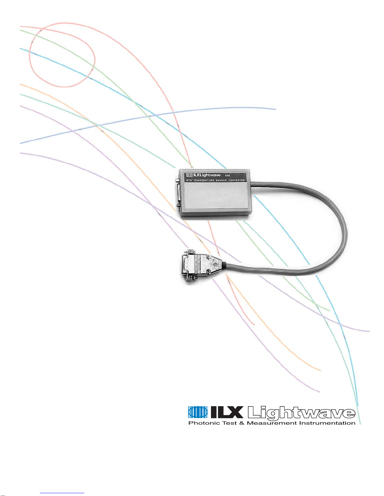
Temperature Sensor Converter
TSC-599
ILX Lightwave Corporation P. O. Box 6310 Bozeman, MT, U.S.A.59771 :· · · 1-800-459-9459 · ·
www.ilxlightwave.com
U.S.& Canada International Inquiries: 406-586-1244 Fax 406-586-9405
E-mail: support@ilxlightwave.com
70009602_R00_06/03


TABLE OF CONTENTS
4_03 TSC-599 i
TABLE OF CONTENTS
Safety Information and the Manual . . . . . . . . . . . . . . . . . . . . . . . . . . . . . . . . . iii
General Safety Considerations . . . . . . . . . . . . . . . . . . . . . . . . . . . . . . . . . . . . iii
Safety Marking Symbols . . . . . . . . . . . . . . . . . . . . . . . . . . . . . . . . . . . . . . . . . iv
Comments, Suggestions, and Problems . . . . . . . . . . . . . . . . . . . . . . . . . . . .vii
Chapter 1 Introduction and Specifications
Product Overview . . . . . . . . . . . . . . . . . . . . . . . . . . . . . . . . . . . . . . . . . . . . . . . . 1
Specifications . . . . . . . . . . . . . . . . . . . . . . . . . . . . . . . . . . . . . . . . . . . . . . . . . . . 2
Chapter 2 Operation
Installation . . . . . . . . . . . . . . . . . . . . . . . . . . . . . . . . . . . . . . . . . . . . . . . . . . . . . . 3
Possible Sources of Error . . . . . . . . . . . . . . . . . . . . . . . . . . . . . . . . . . . . . . . . 3
RTD Non-Linearity . . . . . . . . . . . . . . . . . . . . . . . . . . . . . . . . . . . . . . . . . . . . 3
RTD Self-Heating . . . . . . . . . . . . . . . . . . . . . . . . . . . . . . . . . . . . . . . . . . . . . 4
Ambient Temperature Change . . . . . . . . . . . . . . . . . . . . . . . . . . . . . . . . . . 4
Wire Resistance . . . . . . . . . . . . . . . . . . . . . . . . . . . . . . . . . . . . . . . . . . . . . . 4
Thermocouple Effects . . . . . . . . . . . . . . . . . . . . . . . . . . . . . . . . . . . . . . . . . 4
Setting the Calibration Constants . . . . . . . . . . . . . . . . . . . . . . . . . . . . . . . . . . . 5

TABLE OF CONTENTS
ii TSC-599
TSC-599 iii
SAFETY AND WARRANTY INFORMATION
The Safety and Warranty Information section provides details about cautionary
symbols used in the manual, safety markings used on the instrument, and
information about the Warranty including Customer Service contact information.
Safety Information and the Manual
Throughout this manual, you will see the words
Caution
and
Warning
indicating
potentially dangerous or hazardous situations which, if not avoided, could result in
death, serious or minor injury, or damage to the product. Specifically:
Caution indicates a potentially hazardous situation which can result in minor or
moderate injury or damage to the product or equipment.
Warning indicates a potentially dangerous situation which can result in serious injury or
death.
WARNING
Visible and/or invisible laser radiation. Avoid direct exposure to the beam.
General Safety Considerations
If any of the following conditions exist, or are even suspected, do not use the
instrument until safe operation can be verified by trained service personnel:
•Visible damage
•Severe transport stress
•Prolonged storage under adverse conditions
•Failure to perform intended measurements or functions
If necessary, return the instrument to ILX Lightwave, or authorized local ILX
Lightwave distributor, for service or repair to ensure that safety features are
maintained (see the contact information on page vii).
All instruments returned to ILX Lightwave are required to have a Return
Authorization Number assigned by an official representative of ILX Lightwave
Corporation. See Returning an Instrument on page v for more information.

SAFETY SYMBOLS
iv TSC-599
SAFETY SYMBOLS
This section describes the safety symbols and classifications.
Technical specifications including electrical ratings and weight are included within
the manual. See the Table of Contents to locate the specifications and other
product information. The following classifications are standard across all ILX
Lightwave products:
•Indoor use only
•Ordinary Protection: This product is NOT protected against the harmful ingress of moisture.
•Class I Equipment (grounded type)
•Mains supply voltage fluctuations are not to exceed ±10% of the nominal supply voltage.
•Pollution Degree II
•Installation (overvoltage) Category II for transient overvoltages
•Maximum Relative Humidity: <80% RH, non-condensing
•Operating temperature range of 0 °C to 40 °C
•Storage and transportation temperature of –40 °C to 70 °C
•Maximum altitude: 3000 m (9843 ft.)
•This equipment is suitable for continuous operation.
Safety Marking Symbols
This section provides a description of the safety marking symbols that appear on
the instrument. These symbols provide information about potentially dangerous
situations which can result in death, injury, or damage to the instrument and other
components.
Caution,
refer to
manual
Earth
ground
Te r m i n a l
Alternating
current
Visible and/or
invisible laser
radiation
Caution, risk
of electric
shock
Protective
Conductor
Te r m i n a l
Caution, hot
surface
Frame or
chassis
Termin a l
On: In position of a bistable push control.
The slash (I) only denotes that mains are on.
Off: Out position of a bistable push control.
The circle (O) only denotes that mains are off.
or
(I) or
(O)

WARRANTY
06_03 TSC-599 v
WARRANTY
ILX LIGHTWAVE CORPORATION warrants this instrument to be free from
defects in material and workmanship for a period of one year from date of
shipment. During the warranty period, ILX will repair or replace the unit, at our
option, without charge.
Limitations
This warranty does not apply to fuses, lamps, defects caused by abuse,
modifications, or to use of the product for which it was not intended.
This warranty is in lieu of all other warranties, expressed or implied, including any
implied warranty of merchantability or fitness for any particular purpose. ILX
Lightwave Corporation shall not be liable for any incidental, special, or
consequential damages.
If a problem occurs, please contact ILX Lightwave Corporation with the
instrument's serial number, and thoroughly describe the nature of the problem.
Returning an Instrument
If an instrument is to be shipped to ILX Lightwave for repair or service, be sure to:
1Obtain a Return Authorization number (RA) from ILX Customer Service.
2Attach a tag to the instrument identifying the owner and indicating the required service or
repair. Include the instrument serial number from the rear panel of the instrument.
3Attach the anti-static protective caps that were shipped with the instrument and place the
instrument in a protective anti-static bag.
4Place the instrument in the original packing container with at least 3 inches (7.5 cm) of
compressible packaging material. Shipping damage is not covered by this warranty.
5Secure the packing box with fiber reinforced strapping tape or metal bands.
6Send the instrument, transportation pre-paid, to ILX Lightwave. Clearly write the return
authorization number on the outside of the box and on the shipping paperwork. ILX
Lightwave recommends you insure the shipment.
If the original shipping container is not available, place your instrument in a
container with at least 3 inches (7.5 cm) of compressible packaging material on all
sides.
Repairs are made and the instrument returned transportation pre-paid. Repairs
are warranted for the remainder of the original warranty or for 90 days, whichever
is greater.

WARRANTY
vi TSC-599
Claims for Shipping Damage
When you receive the instrument, inspect it immediately for any damage or
shortages on the packing list. If the instrument is damaged, file a claim with the
carrier. The factory will supply you with a quotation for estimated costs of repair.
You must negotiate and settle with the carrier for the amount of damage.

WARRANTY
06_03 TSC-599 vii
Comments, Suggestions, and Problems
To ensure that you get the most out of your ILX Lightwave product, we ask that
you direct any product operation or service related questions or comments to ILX
Lightwave Customer Support. You may contact us in whatever way is most
convenient:
Phone . . . . . . . . . . . . . . . . . . . . . . . . . . . (800) 459-9459 or (406) 586-1244
Fax . . . . . . . . . . . . . . . . . . . . . . . . . . . . . . . . . . . . . . . . . . . . . (406) 586-9405
On the web at: . . . . . . . . . . . . . . . . . . . . . . . . . . . . . . . . . . . .ilx.custhelp.com
Or mail to:
ILX Lightwave Corporation
P. O. Box 6310
Bozeman, Montana, U.S.A 59771
www.ilxlightwave.com
When you contact us, please have the following information:
If ILX Lightwave determines that a return to the factory is necessary, you are
issued a Return Authorization (RA) number. Please mark this number on the
outside of the shipping box.
You or your shipping service are responsible for any shipping damage when
returning the instrument to ILX Lightwave; ILX recommends you insure the
shipment. If the original shipping container is not available, place your instrument
Model Number:
Serial Number:
End-user Name:
Company:
Phone:
Fax:
Description of what is
connected to the ILX
Lightwave instrument:
Description of the problem:

WARRANTY
viii TSC-599
in a container with at least 3 inches (7.5 cm) of compressible packaging material
on all sides.
We look forward to serving you even better in the future!

TSC-599 1
CHAPTER 1
INTRODUCTION AND SPECIFICATIONS
This manual contains information for using the 599 RTD Temperature Sensor
Converter, as well as procedures for optimizing the calibration of your temperature
sensor. By following these procedures, the user will be able to achieve the most
accurate results.
Product Overview
The 599 RTD Temperature Sensor Converter is a device which allows an RTD, or
resistance temperature detector, to be used as a temperature sensor with the ILX
Lightwave LDT-5910B, LDT-5525 Temperature Controllers, ILX Lightwave Laser
Diode Controllers (LDC-3700 Series), and the LPA-9000 Series Laser Parameter
Analyzers. The 599 is designed to be used with 100 ohm, 500 ohm and 1Kohm
two-lead RTDs.
INTRODUCTION AND SPECIFICATIONS
Specifications
2 TSC-599
CHAPTER 1
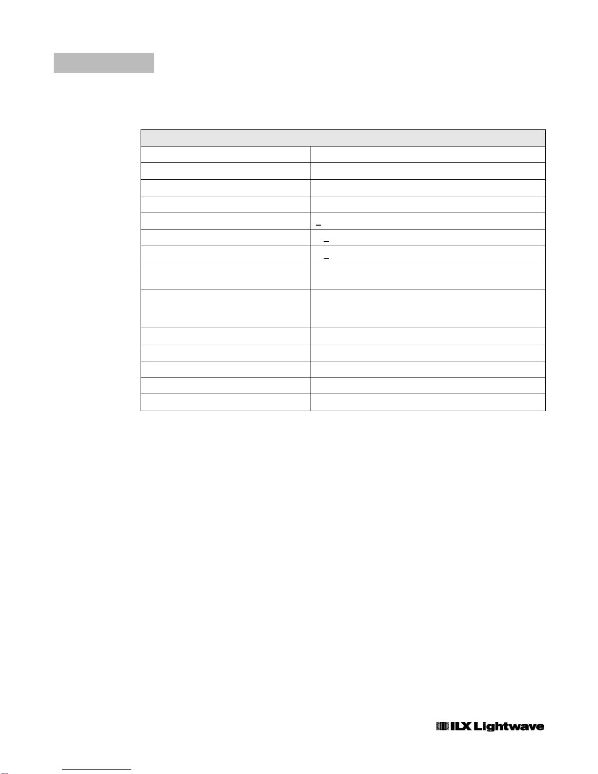
Specifications
1. Input connector pin configuration is compatible with the ILX Lightwave LDT-5910B, LDT-5525 Temperature Controllers, ILX
Lightwave Laser Diode Controllers (LDC-3700 Series) and the LPA-9000 Series Laser Parameter Analyzers.
2. Sensor resistance setting is internally switch selectable.
3. Specification of ILX Lightwave LDT-5910B Temperature Controller used with the 599 RTD Temperature Sensor Converter and a
100 ohm platinum RTD temperature sensor.
4. Typical specification; set-point accuracy depends upon user-defined calibration constants, ambient temperature fluctuations, the
particular temperature sensor used and other factors.
Connectors115-pin D-subminiature
Sensor Type22-wire RTD (1K, 500 and 100 ohm)
Sensor Current (mA) 2.0 mA
Temperature Readout Range -20 oC to +100 oC
RTD Set Point Accuracy3,4 +0.2 oC
Short Term Stability (10 minutes)3< + 0.01 oC
Long Term Stability (24 hours)3< + 0.02 oC
Error Due to a Temperature Change of
Enclosure 0.04% / oC
Typical Temperature Readout Error Due
to RTD Non-Linearity
(-20 oC to + 100 oC)
0.75 oC
Size 0.9” x 2.4” x 3.8”
Weight 6.75 ounces (191 grams)
Operating Temperature 0 oC to 40 oC
Storage Temperature -40 oC to +70 oC
Humidity < 95% relative humity, non-condensing

TSC-599 3
CHAPTER 2
OPERATION
Installation
Prior to installing the 599, the RTD sensor type must be selected. Open the 599
enclosure by removing the two #2 Phillips-head screws. Position the large slide
switch into either the 100 ohm, 500 ohm or 1Kohm position depending on the RTD
sensor type used. (Switch positions are labeled on the printed circuit board.)
Reassemble the 599 enclosure.
Note: Opening the 599 enclosure will NOT void the ILX Lightwave Warranty. However, the
user should not adjust any internal trimpots, as the 599 has been factory calibrated.
To install the 599 Temperature Sensor Converter, first position the sensor select
switch of your ILX Lightwave Temperature Controller to the “AD590” position.
Then plug the 15-pin male D-subminiature connector on the 599 into the 15-pin
female D-subminiature connector on the rear panel of the temperature controller.
The 15-pin female D-sub connector on the 599 will now function the same as the
15-pin D-sub connector on the back of the temperature controller (with the
exception that an RTD temperature sensor, instead of an AD590 sensor, should
be connected to pins seven and eight). Refer to the appropriate ILX Lightwave
Temperature Controller Manual for temperature control operation.
Possible Sources of Error
The following sections outline several factors which may reduce the accuracy of
the 599 RTD Temperature Sensor Converter. ILX suggests that the user follow the
outlined suggestions to minimize the influence of these factors.
RTD Non-Linearity
By a first approximation, the change in resistance of an RTD with respect to
temperature is given by:
R = Ro(1 + αT)

OPERATION
Installation
4 TSC-599
CHAPTER 2
where Rois the resistance of the RTD at 0 oC, T is the temperature in Celsius and
αis a constant. However, this approximation is not completely accurate, as an
RTD is typically about 0.5% non-linear in the range between 0 and 100 oC. The
599 RTD Temperature Sensor Converter gives a linear response for a change in
sensor resistance, R. The formula for the temperature displayed on the
temperature controller (in oC) is given by:
Tdisplay = C1 + C2 * (K * R - 273.15)
where C1 and C2 are the calibration constants set on the temperature controller,
and K is an internally-set constant. To reduce the error due to non-linearity of the
RTD, the calibration constants C1 and C2 should be set using the two-point
calibration method. The two points should be as close together as possible (while
still spanning the region of interest). Refer to a later section for a description of the
two-point calibration.
RTD Self-Heating
The error due to self-heating of the RTD will vary, depending on the size and
shape of the RTD and the thermal environment. To minimize this error, the
calibration constants on the temperature sensor should be set with the RTD in the
same type of thermal environment in which is will be used.
Ambient Temperature Change
The change in ambient temperature surrounding the enclosure will effect the
temperature reading slightly. To minimize this error, the temperature controller and
the 599 should be warmed-up properly prior to calibration (approximately 1 hour is
sufficient) and the room temperature should be fairly stable.
Wire Resistance
The wire used to connect the RTD to the 599 Temperature Converter will add
some small error. However, this error may be offset by properly adjusting the
calibration constant C1.
Thermocouple Effects
This effect is usually quite small and can be minimized by property selecting the
type of wire used to connect the RTD leads to the 599 Temperature Converter. In
addition, these effects may be offset by properly adjusting the calibration constant
C1.

OPERATION
Setting the Calibration Constants
06_03 TSC-599 5
CHAPTER 2
Setting the Calibration Constants
For a firs approximation, the calibration constants C1 and C2 may be set by using
the following equations. This will usually give an accuracy within 1 oC.
C1 = 0
C2 = 1 / 273.15 * α
Here αis a constant dependent upon the particular RTD. Two common values of
αare 0.00385 and 0.00392.
If more accuracy is desired, the two-point calibration method may be used. The
accuracy of this procedure depends upon the accuracy of the known
temperatures, externally measured. It is used to determine the zero offset and the
gain offset (slope) of the RTD device.
The two-point calibration procedure is outlined below:
1Connect the RTD to the 599 Temperature Converter unit. Connect the 599 Temperature
Converter to the Temperature Controller and allow the Temperature Controller to warm up
for at least 1 hour.
2Select the C1 parameter of the Temperature Controller and enter a value for C1. Read
and record the value of C1. Next, select the C2 parameter and enter a value for C2. Read
and record the value of C2. (The user may with to use the formulas for C1 and C2 as a
first approximation.)
3Set up the Temperature Controller for constant temperature operation. Place the sensor at
an accurately known and stable temperature Ta1. Allow the temperature controller to
stabilize and read the displayed temperature, Td1. Record these values.
4Repeat step 3 for another known temperature, Ta2, and the corresponding displayed
temperature, Td2.
Note: The two temperature,Ta1 and Ta2, should be at the bounds of the intended operating
range. For best results, make the range between the two temperatures as small as
possible, while still covering the temperature range of interest.
5Calculate the new values of C1 (C1new) and C2 (C2new) using the following equations:
First, determine the intermediate values of V and U, where:
V = ( Ta1 - Ta2 ) / ( Td1 - Td2 ), and
U = Ta1 - ( Td1 * V )
C1new and C2new can then be determined with the following:
C1new = U + ( V * C1 )
C2new = V * C2
6Replace C1 with C1new by selecting the C1 parameter of the Temperature Controller and
entering the new value, C1new. Similarly, replace C2 with C2new. It is not necessary to
repeat the calibration procedure at this point.

OPERATION
Setting the Calibration Constants
6 TSC-599
CHAPTER 2
Table of contents


