Lavry LavryBlack Series User manual

LavryBlack Series
Model DA10
Digital to Analog Converter
Lavry Engineering, Inc.
945 Hildebrand Lane
Suite 110
Bainbridge Island, WA 98110
http://lavryengineering.com
email: [email protected]
February 17, 2006

2
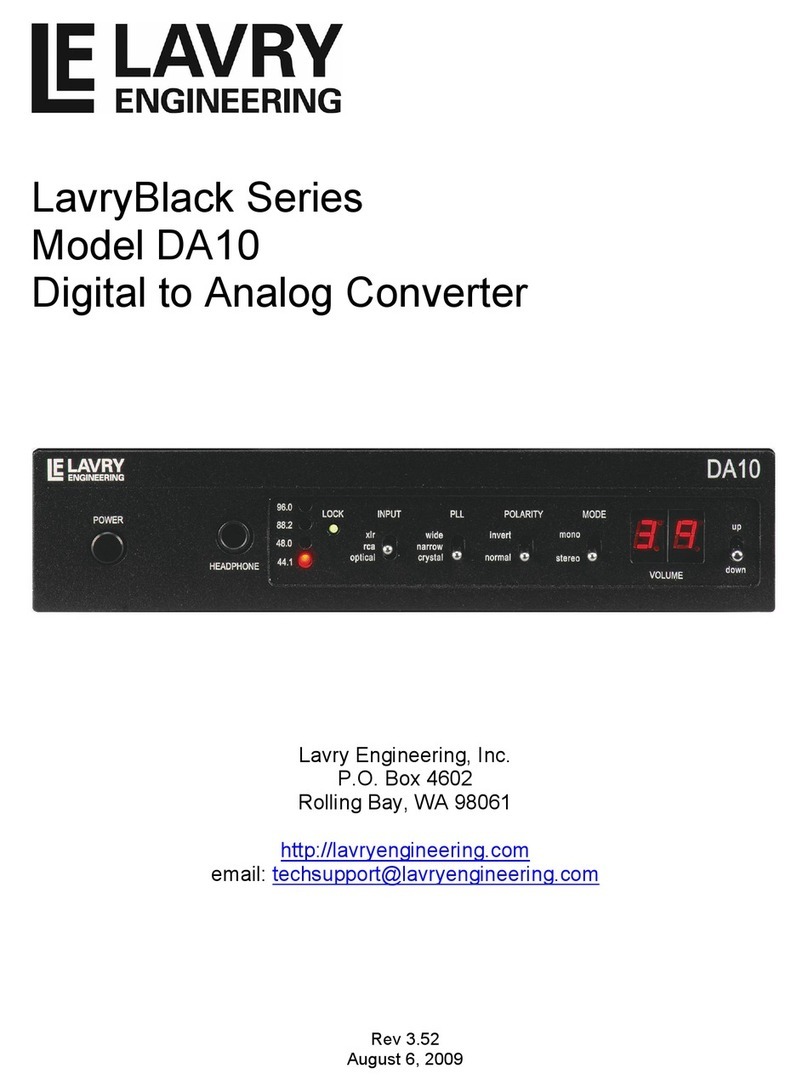
MODEL DA10
The LavryBlack DA10 features:
- Ultra low jitter modes (without sample rate conversion).
- Included sample rate conversion for non standard rates.
- Potentiometer free digitally controlled analog volume control.
- High power discrete headphone output.
- XLR, Coaxial (RCA) and Optical (Toslink light pipe) inputs.
- Stereo/Mono switch (for monitoring of stereo sound field).
- Polarity Inversion.
- Optional twin DA10 19 inch rack mount kit. (available soon)
CONNECTIONS:
CAUTION:
Please switch OFF and disconnect power to all devices before connection.
Connect a Digital INPUT from your source using any or all of the following:
- XLR cable to the AES connector.
- Toslink light pipe to OPTICAL (after removing the Optical dust cover).
- Coaxial cable to the SPDIF connector.
Note:
All the connectors can receive either AES/EBU (professional format) or SPDIF (consumer
format).
Connect the XLR OUTPUTS to your destination device (receiver, power amplifier or powered
speaker).
- THE XLR marked RIGHT to the RIGHT Channel of the destination.
- THE XLR marked LEFT to the LEFT Channel of the destination.
- Connect headphones to the HEADPHONE jack.
- Connect the AC power cord to the rear power entry receptacle.
- Connect the DA10 and other devices to an AC power source.

3
CONFIGURING THE XLR OUTPUTS:
The unit is factory configured to operate in Balanced output mode. The balanced signal comes
out PIN 2 and PIN 3 of the XLR outputs. PIN 1 is a ground connection for the cable shield. The
unit may be configured (via internal jumpers) to drive Unbalanced signals only, but the Balanced
configuration can be made to drive an Unbalanced load when using the proper
interconnecting cables as follows:
Alternative 1: Use PIN 2 for the signal and leave PIN 3 unconnected.
Alternative 2: Use PIN 3 for the signal and leave PIN 2 unconnected.
In both cases, PIN 1 is used for signal ground return. You may also tie a shield to PIN 1.
Note: Most XLR cable adaptors (such as a cable with XLR Female and a ¼ inch MONO plug)
work correctly as Balanced to Unbalanced converters.
Rear Panel
OPERATION:
A. PLL SETTINGS:
Use Crystal or Narrow settings for 44.1, 48, 88.2 and 96KHz rates.
For stereo operation use CRYSTAL mode. When using multiple DA10 units use NARROW mode.
When a unit is locked to an input (LOCK lamp is ON), the received rate is indicated by a lamp.
Use WIDE for non standard frequencies between 30KHz and 200KHz.
When set to WIDE, all 4 lamps (44.1, 48, 88.2 and 96KHz) are ON.
Before turning the DA10 ON, select the PLL mode (Crystal, Narrow, or Wide).
Changing between Crystal and Narrow while the power is ON may take up to 50 seconds
to take full effect.
B. AVOIDING CLICKS:
The DA10 provides protection against “power ON clicks”.
Switching between input sources (XLR, RCA or OPTICAL) and PLL modes (WIDE, NARROW
or CRYSTAL) during operation may cause unwanted clicks, especially when the signal is loud.
To avoid unwanted clicks when the unit is powered ON, it is advisable to reduce the volume down
when operating the INPUT switch, (XLR, RCA or OPTICAL) or the PLL switch (WIDE, NARROW
or CRYSTAL).

4
C. VOLUME CONTROL:
Note: the unit is shipped in BALANCED configuration. Internal jumpers enable Unbalanced
operation with PIN 2 or PIN 3 HOT. Moving Jumpers is not usually required. See “Configuring the
XLR Outputs”
Volume Balanced Unbalanced Headphone
Setting Configuration Configuration Level
----------------------------------------------------------------------------------
56 24dBu 18dBu 20dBu
55 23dBu 17dBu 19dBu
54 22dBu 16dBu 18dBu
--- --------- --------- ---------
--- --------- --------- ---------
01 -31dBu -37dBu -35dBu
00 OFF OFF OFF
The volume setting is non volatile – the unit recalls the last setting when powered ON.
D. MONO and POLARITY:
For normal use set to STEREO position. MONO mode is provided for monitoring the impact of the
stereo sound field. The MONO signal is the AVERAGE (sum divided by 2) of the L and R signals.
Both MONO and INVERT can be switched during operation.
SPECIFICATIONS:
THD+N at max volume (volume = 55) – typical, 0.0008% FS, maximum 0.0013% FS
Test conditions: 20Hz – 20KHz, -3dBFS sine wave, 22-22KHz BW
At all possible settings and switch combinations.
Dynamic Range: -110dB typical, -109 dB minimum
Test conditions: Non weighted
At all possible settings and switch combinations.
Drive Capability:
24dBu Balanced XLR output into 1K ohms at Volume = 56 or lower
21dBu Balanced XLR output into 600 ohms at Volume = 53 or lower
18dBu Unbalanced XLR output into 600 ohms at Volume = 56 or lower
20dBu Headphone into 100 ohms at Volume = 56 or lower
20dBu Headphone into 50 ohms at Volume = 50 or lower
Volume Control Precision:
Integral linearity (deviation from straight line) – better than 0.1dB
Differential linearity (step size) – better than 0.08dB
AC Power:
Voltage 90-264 VAC, Frequency 40-63Hz, Current 0.1A
Fuse Rating 2.5A

5
LIMITED WARRANTY – LAVRYBLACK SERIES MODEL DA10
Subject to the conditions set forth below, for six months after the original purchase date of the
product, Lavry Engineering will repair the product free of charge in the United States in the event
of a defect in materials or workmanship.
Lavry Engineering may exchange new or rebuilt parts for defective parts. Please call the factory
for an RMA number prior to shipment. No product will be accepted for warranty service without
a pre-issued RMA number.
This warranty is extended only to an original purchaser of the product from Lavry Engineering, or
an authorized reseller of Lavry Engineering. Products that are purchased from unauthorized
resellers do not have any warranty coverage. A valid purchase receipt or other valid proof of
purchase will be required before warranty service is provided. This warranty only covers failures
due to defects in materials or workmanship and does not cover damages which occur in shipment
or failures resulting from accident, misuse, line power surges, mishandling, maintenance,
alterations and modifications of the product, or service by an unauthorized service center or
personnel. Lavry Engineering reserves the right to deny warranty service to products that have
been used in rental, service bureau, or similar businesses.
This limited warranty gives you specific legal rights. You may have others which vary from
state/jurisdiction to state/jurisdiction.
LIMITS AND EXCLUSIONS
LAVRY ENGINEERING DOES NOT, BY VIRTUE OF THIS AGREEMENT, OR BY ANY
COURSE OF PERFORMANCE, COURSE OF DEALING, OR USAGE OF TRADE, MAKE
ANY OTHER WARRANTIES, EXPRESS OR IMPLIED, INCLUDING, WITHOUT
LIMITATION, ANY WARRANTY OF MERCHANTABILITY, FITNESS FOR A
PARTICULAR PURPOSE, TITLE OR NONINFRINGEMENT, AND ALL SUCH
WARRANTIES ARE HEREBY EXPRESSLY DISCLAIMED. LAVRY ENGINEERING
EXPRESSLY DISCLAIMS ANY IMPLIED INDEMNITIES. LAVRY ENGINEERING SHALL
NOT BE LIABLE FOR ANY INDIRECT, INCIDENTAL, CONSEQUENTIAL, PUNITIVE,
SPECIAL OR EXEMPLARY LOSSES OR DAMAGES, INCLUDING, WITHOUT
LIMITATION, DAMAGES TO RECORDINGS, TAPES OR DISKS, DAMAGES FOR LOSS
OF BUSINESS PROFITS, BUSINESS INTERRUPTION, LOSS OF BUSINESS
INFORMATION, LOSS OF GOODWILL, COVER, OR OTHER PECUNIARY LOSS,
ARISING OUT OF OR RELATING TO THE USE OF THE PRODUCT, OR ARISING FROM
BREACH OF WARRANTY OR CONTRACT, NEGLIGENCE, OR ANY OTHER LEGAL
THEORY, EVEN IF LAVRY ENGINEERING HAS BEEN ADVISED OF THE POSSIBILITY
OF SUCH LOSSES OR DAMAGES. ANY DAMAGES THAT Lavry ENGINEERING IS
REQUIRED TO PAY FOR ANY PURPOSE WHATSOEVER SHALL NOT EXCEED THE
ORIGINAL COST PAID TO LAVRY ENGINEERING FOR THE APPLICABLE PRODUCT.
BECAUSE SOME STATES/JURISDICTIONS DO NOT ALLOW THE EXCLUSION OR
LIMITATION OF LIABILITY FOR CONSEQUENTIAL OR INCIDENTAL DAMAGES, THE
FOREGOING LIMITATION MAY NOT APPLY TO YOU.
Other manuals for LavryBlack Series
1
This manual suits for next models
1
Table of contents
Other Lavry Media Converter manuals