manuals.online logo
Brands
  1. Home
  2. •
  3. Brands
  4. •
  5. Lika
  6. •
  7. Media Converter
  8. •
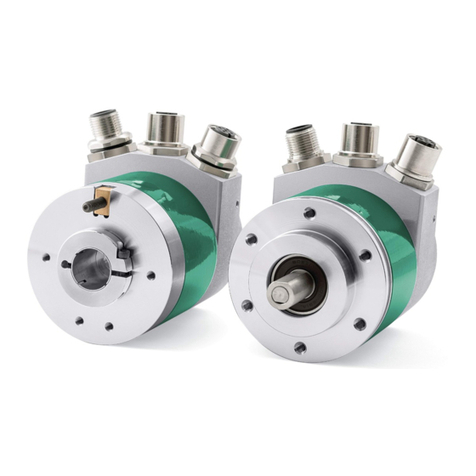
  9. Lika EM58 PA Series User manual

Lika EM58 PA Series User manual

User's guide
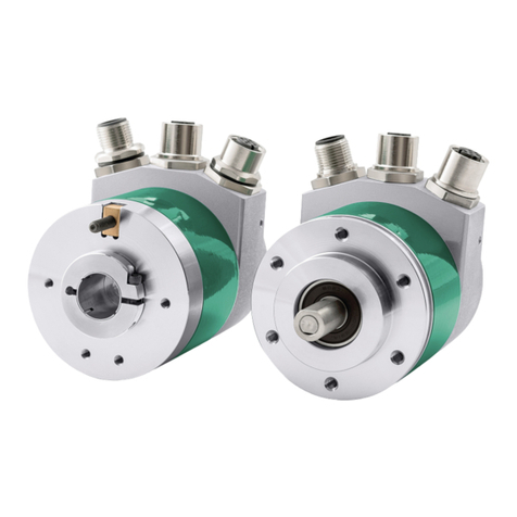
EM58 PA
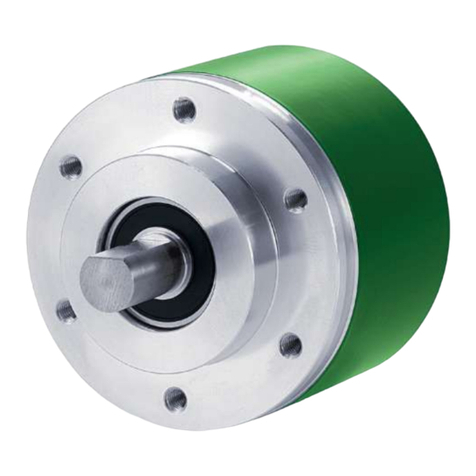
Programmable encoder
•Programmable analogue encoder
•Current and voltage programmable outputs
•24 bit resolution (4, 96 cpr x 16,384 rev.)
•Programmable scaling and TEACH-IN function
•Programmable overrun mode
•Solid and hollow shaft versions
•Free-of-charge programming software
Suitable for the following models:
•EM5812/16384PA...
•EM58S12/16384PA...
•EMC5812/16384PA...
•EMC5912/16384PA...
•EMC6 12/16384PA...
Table of Contents
Preliminary information 8
Safety summary 9
Identification 11
Mechanical installation 12
Electrical connection 17
Software and configuration parameters 27
Default parameters list 58
Lika Electronic • Tel. +39 445 8 66 • [email protected] • www.lika.biz
Smart encoders & actuators
This publication was produced by Lika Electronic s.r.l. 2020. All rights reserved. Tutti i diritti riservati. Alle Rechte vorbehalten. Todos los
derechos reservados. Tous droits réservés.
This document and in ormation contained herein are the property o Lika Electronic s.r.l. and shall not be reproduced in whole or in
part without prior written approval o Lika Electronic s.r.l. Translation, reproduction and total or partial modi ication (photostat copies,
ilm and micro ilm included and any other means) are orbidden without written authorisation o Lika Electronic s.r.l.
The in ormation herein is subject to change without notice and should not be construed as a commitment by Lika Electronic s.r.l. Lika
Electronic s.r.l. reserves the right to make all modi ications at any moments and without orewarning.
This manual is periodically reviewed and revised. As required we suggest checking i a new or updated edition o this document is
available at Lika Electronic s.r.l.'s website. Lika Electronic s.r.l. assumes no responsibility or any errors or omissions in this document.
Critical evaluation o this manual by the user is welcomed. Your comments assist us in preparation o uture documentation, in order
to make it as clear and complete as possible. Please send an e-mail to the ollowing address in [email protected] or submitting your
comments, suggestions and criticisms.
General contents
User's guide............................................................................................................................................................................................1
General contents.............................................................................................................................................................................3
Subject index.....................................................................................................................................................................................6
Typographic and iconographic conventions...................................................................................................................7
Preliminary information..............................................................................................................................................................8
1 Safety summary..................................................................................................................................... 9
1.1 Sa ety.............................................................................................................................................................................9
1.2 Electrical sa ety.........................................................................................................................................................9
1.3 Mechanical sa ety..................................................................................................................................................10
2 Identification....................................................................................................................................... 11
3 Mechanical installation..................................................................................................................... 12
3.1 Encoder with solid sha t EM58, EM58S.......................................................................................................12
3.1.1 Customary installation................................................................................................................................12
3.1.2 Installation using ixing clamps (optional kit code LKM-386)...................................................13
3.1.3 Installation using a mounting bell (optional kit code PF4256).................................................13
3.2 Encoder with hollow sha t................................................................................................................................14
3.2.1 EMC58 PA installation using the antirotation pin..........................................................................14
3.2.2 EMC59 PA installation using the ixing plate...................................................................................15
3.2.3 EMC60 PA installation using the antirotation pin and the ixing plate................................16
4 Electrical connection.......................................................................................................................... 17
4.1 Cable and connectors connections................................................................................................................17
4.2 T12 cable speci ications......................................................................................................................................17
4.3 M23H 12-pin (counter-clockwise) connector speci ications.............................................................18
4.4 M12 12-pin connector speci ications...........................................................................................................18
4.5 Connection o the shield....................................................................................................................................18
4.6 Ground connection...............................................................................................................................................19
4.7 RS-232 serial connection...................................................................................................................................19
4.8 0Vdc.............................................................................................................................................................................20
4.9 Fault output.............................................................................................................................................................20
4.9.1 Fault output connected to a PLC input................................................................................................21
4.9.2 Fault output connected to a relay.........................................................................................................22
4.10 Current analogue output.................................................................................................................................22
4.11 Voltage analogue output.................................................................................................................................23
4.12 Counting direction.............................................................................................................................................24
4.13 Preset........................................................................................................................................................................25
4.14 Recommended current analogue output circuit...................................................................................25
4.15 Recommended voltage analogue output circuit...................................................................................26
5 Software and configuration parameters.......................................................................................27
5.1 Con iguring the device using the Lika Electronic so tware tool.......................................................27
5.1.1 Available pages and commands..............................................................................................................28
5.2 IDENTIFICATION page...........................................................................................................................................28
5.2.1 COM PORT box................................................................................................................................................31
Device search..........................................................................................................................................................31
Port...............................................................................................................................................................................31
5.2.2 ENCODER box..................................................................................................................................................32
Device type..............................................................................................................................................................32
Serial number.........................................................................................................................................................32
Output type.............................................................................................................................................................32
Version........................................................................................................................................................................32
Read parameters..................................................................................................................................................32
Load default parameters.................................................................................................................................32
5.3 CONFIGURATION page.........................................................................................................................................33
5.3.1 POSITION box...................................................................................................................................................33
Position......................................................................................................................................................................34
Turns............................................................................................................................................................................34
Counts/rev................................................................................................................................................................34
5.3.2 PRESET box.......................................................................................................................................................34
Preset..........................................................................................................................................................................34
Activate preset......................................................................................................................................................36
5.3.3 DIAGNOSTICS box..........................................................................................................................................36
Encoder travel not valid: counts to be displayed greater than physical resolution
between start and stop...............................................................................................................................36
Encoder travel not valid: unable to reach the minimum stroke.............................................36
No error.....................................................................................................................................................................37
5.3.4 ENCODER CONFIGURATION box..............................................................................................................37
Enable analog output........................................................................................................................................37
Enable preset..........................................................................................................................................................37
Positive counting direction............................................................................................................................37
Output type.............................................................................................................................................................38
Output range..........................................................................................................................................................38
5.3.5 RESOLUTION SETTING box.........................................................................................................................39
Programming mode: Start / Stop (single ramp)................................................................................41
1 – Start teaching...............................................................................................................................................43
2 - Stop teaching.................................................................................................................................................43
Programming mode: Start / Stop (cyclic ramp).................................................................................44
1 – Start teaching...............................................................................................................................................46
2 - Stop teaching.................................................................................................................................................46
Programming mode: Prog (single ramp)................................................................................................47
Encoder HW counts............................................................................................................................................48
Programming mode: Prog (cyclic ramp).................................................................................................50
Encoder HW counts............................................................................................................................................51
5.3.6 ENCODER SPECIFICATIONS box...............................................................................................................52
Counts per revolution.......................................................................................................................................52
Max number of revolutions...........................................................................................................................52
Max total counts..................................................................................................................................................52
5.4 LOAD / SAVE CONFIGURATION page.............................................................................................................54
5.4.1 Saving the encoder con iguration to a ile........................................................................................54
5.4.2 Loading the encoder con iguration rom a ile................................................................................55
5.5 Error messages........................................................................................................................................................56
Carattere non valido.................................................................................................................................................56
Disconnected cable...................................................................................................................................................56
Encoder HW counts to be converted into the selected output range must be lower than the
maximum total counts........................................................................................................................................56
Error creating the ile...............................................................................................................................................56
Error reading the ile................................................................................................................................................56
Value not valid: preset greater than the maximum position..................................................................56
6 Default parameters list......................................................................................................................58
Subject index
1
1 – Start teaching....................................................43, 46
2
2 - Stop teaching.....................................................43, 46
A
Activate preset..................................................................36
C
Carattere non valido.......................................................56
Counts per revolution....................................................52
Counts/rev...........................................................................34
D
Device search.....................................................................31
Device type.........................................................................32
Disconnected cable.........................................................56

E
Enable analog output.....................................................37
Enable preset......................................................................37
Encoder HW counts.................................................48, 51
Encoder HW counts to be converted.......................56
Encoder travel not valid: counts to be displayed
greater than physical resolution between start
and stop...........................................................................36
Encoder travel not valid: unable to reach the
minimum stroke...........................................................36
Error creating the ile.....................................................56
Error reading the ile......................................................56
L
Load de ault parameters...............................................32
M
Max number o revolutions.........................................52
Max total counts..............................................................52
N
No error................................................................................37
O
Output range......................................................................38
Output type.................................................................32, 38
P
Port.........................................................................................31
Position.................................................................................34
Positive counting direction..........................................37
Preset.....................................................................................34
Programming mode: Prog (cyclic ramp)................50
Programming mode: Prog (single ramp)................47
Programming mode: Start / Stop (cyclic ramp)..44
Programming mode: Start / Stop (single ramp)..41
R
Read parameters...............................................................32
S
Serial number....................................................................32
T
Turns......................................................................................34
V
Value not valid: preset...................................................56
Version..................................................................................32
Typographic and iconographic conventions
In this guide, to make it easier to understand and read the text the ollowing typographic and
iconographic conventions are used:
•parameters and objects both o Lika device and inter ace are coloured in GREEN;
•alarms are coloured in RED;
•states are coloured in FUCSIA.
When scrolling through the text some icons can be ound on the side o the page: they are expressly
designed to highlight the parts o the text which are o great interest and signi icance or the user.
Sometimes they are used to warn against dangers or potential sources o danger arising rom the use o
the device. You are advised to ollow strictly the instructions given in this guide in order to guarantee the
sa ety o the user and ensure the per ormance o the device. In this guide the ollowing symbols are
used:
This icon, ollowed by the word WARNING, is meant to highlight the parts o the
text where in ormation o great signi icance or the user can be ound: user must
pay the greatest attention to them! Instructions must be ollowed strictly in order
to guarantee the sa ety o the user and a correct use o the device. Failure to heed
a warning or comply with instructions could lead to personal injury and/or damage
to the unit or other equipment.
This icon, ollowed by the word NOTE, is meant to highlight the parts o the text
where important notes need ul or a correct and reliable use o the device can be
ound. User must pay attention to them! Failure to comply with instructions could
cause the equipment to be set wrongly: hence a aulty and improper working o
the device could be the consequence.
This icon is meant to highlight the parts o the text where suggestions use ul or
making it easier to set the device and optimize per ormance and reliability can be
ound. Sometimes this symbol is ollowed by the word EXAMPLE when instructions
or setting parameters are accompanied by examples to clari y the explanation.
Preliminary information
This guide is designed to provide the most complete and exhaustive in ormation the operator needs to
correctly and sa ely install and operate the EM58 PA absolute multiturn programmable encoder
fitted with current and voltage analogue output.
EM58 PA programmable encoder rom Lika Electronic is designed to maximize customization and
versatility and really allows the operator to get, along with the absolute position in ormation, a complete
parametrization and the better con iguration that per ectly suit speci ic needs in a good many
applications and machines. The operator in act can not only choose the type o analogue output
required by the controller and application (current or voltage) and the range o output (0-5V; 0-10V; -5
÷ +5V; -10 ÷ +10V; 4-20mA; 0-20mA; 0-24mA); but also set the desired resolution in the range o max.
12 bits singleturn (4,096 in ormation per revolution) and 14 bits multiturn (16,384 revolutions). Please
note that the encoder uses an internal 16-bit DAC or conversion.
EM58 PA programmable encoder is available in both hollow and solid sha t versions.
The parametrization and set up o the EM58 PA programmable encoder is achieved through a so tware
expressly developed and released by Lika Electronic. The program is supplied or ree and can be installed
in any PC itted with a Windows operating system (Windows XP or later). It allows the operator to set the
working parameters o the device and monitor whether the device is running properly. Communication is
established using RS-232 serial cable and port. The so tware tool is compatible with the whole series
o HM- and EM- programmable encoders: programmable encoder with SSI serial output (PS code),
programmable encoder with parallel output (PN and PY codes), programmable encoder with analogue
output (PA code).
To make it easier to read and understand the text, this guide is divided into two main sections.
In the irst section some general in ormation concerning the sa ety, the mechanical installation and the
electrical connection as well as tips or setting up and running properly and e iciently the unit are
provided.
In the second section, entitled Software and configuration parameters, the parameters implemented
in the unit are ully described.
EM58 PA
1 Safety summary
1.1 Safety
•Always adhere to the pro essional sa ety and accident prevention
regulations applicable to your country during device installation and
operation;
•installation and maintenance operations have to be carried out by
quali ied personnel only, with power supply disconnected and stationary
mechanical parts;
•device must be used only or the purpose appropriate to its design: use or
purposes other than those or which it has been designed could result in
serious personal and/or the environment damage;
•high current, voltage and moving mechanical parts can cause serious or
atal injury;
•warning ! Do not use in explosive or lammable areas;
•ailure to comply with these precautions or with speci ic warnings
elsewhere in this manual violates sa ety standards o design, manu acture,
and intended use o the equipment;
•Lika Electronic assumes no liability or the customer's ailure to comply
with these requirements.
1.2 Electrical safety
•Turn OFF the power supply be ore connecting the device;
•connect according to explanation in the ”Electrical connection” section on
page 17;
•the wires o unused output signals must be cut at di erent lengths and
insulated singularly;
•in compliance with 2014/30/EU norm on electromagnetic
compatibility, ollowing precautions must be taken:
-be ore handling and installing the equipment, discharge
electrical charge rom your body and tools which may come in touch
with the device;
- power supply must be stabilized without noise; install EMC ilters on
device power supply i needed;
- always use shielded cables (twisted pair cables whenever possible);
- avoid cables runs longer than necessary;
- avoid running the signal cable near high voltage power cables;
- mount the device as ar as possible rom any capacitive or inductive
noise source; shield the device rom noise source i needed;
- to guarantee a correct working o the device, avoid using strong magnets
on or near by the unit;
MAN EM58 PA E 1.1 Sa ety summary 9 o 60
EM58 PA
- minimize noise by connecting the shield and/or the connector housing
and/or the rame to ground. Make sure that ground is not a ected by
noise. The connection point to ground can be situated both on the device
side and on user’s side. The best solution to minimize the inter erence
must be carried out by the user.
1.3 Mechanical safety
•Install the device ollowing strictly the in ormation in the “Mechanical
installation” section on page 12;
•mechanical installation has to be carried out with stationary mechanical
parts;
•do not disassemble the unit;
•do not tool the unit or its sha t;
•delicate electronic equipment: handle with care; do not subject the device
and the sha t to knocks or shocks;
•respect the environmental characteristics o the product;
•unit with solid sha t: in order to guarantee the maximum reliability over
time o the mechanical parts, we recommend a lexible coupling to be
installed to connect the encoder and the installation sha t; make sure the
misalignment tolerances o the lexible coupling are respected;
•unit with hollow sha t: the encoder can be mounted directly on a sha t
whose diameter has to respect the technical characteristics speci ied in the
purchase order and clamped by means o the collar and the ixing plate
into which an anti-rotation pin has to be inserted.
MAN EM58 PA E 1.1 Sa ety summary 10 o 60
EM58 PA
2 Identification
Device can be identi ied through the order code and the serial number printed
on the label applied to its body. In ormation is listed in the delivery document
too. Please always quote the order code and the serial number when reaching
Lika Electronic or purchasing spare parts or needing assistance. For any
in ormation on the technical characteristics o the product re er to the technical
catalogue.
Warning: encoders having order code ending with "/Sxxx" may have
mechanical and electrical characteristics di erent rom standard and
be supplied with additional documentation or special connections
(Technical In o).
MAN EM58 PA E 1.1 Identi ication 11 o 60
EM58 PA
3 Mechanical installation
WARNING
Installation and maintenance operations has to be carried out by quali ied
personnel only, with power supply disconnected and mechanical parts
compulsorily in stop.
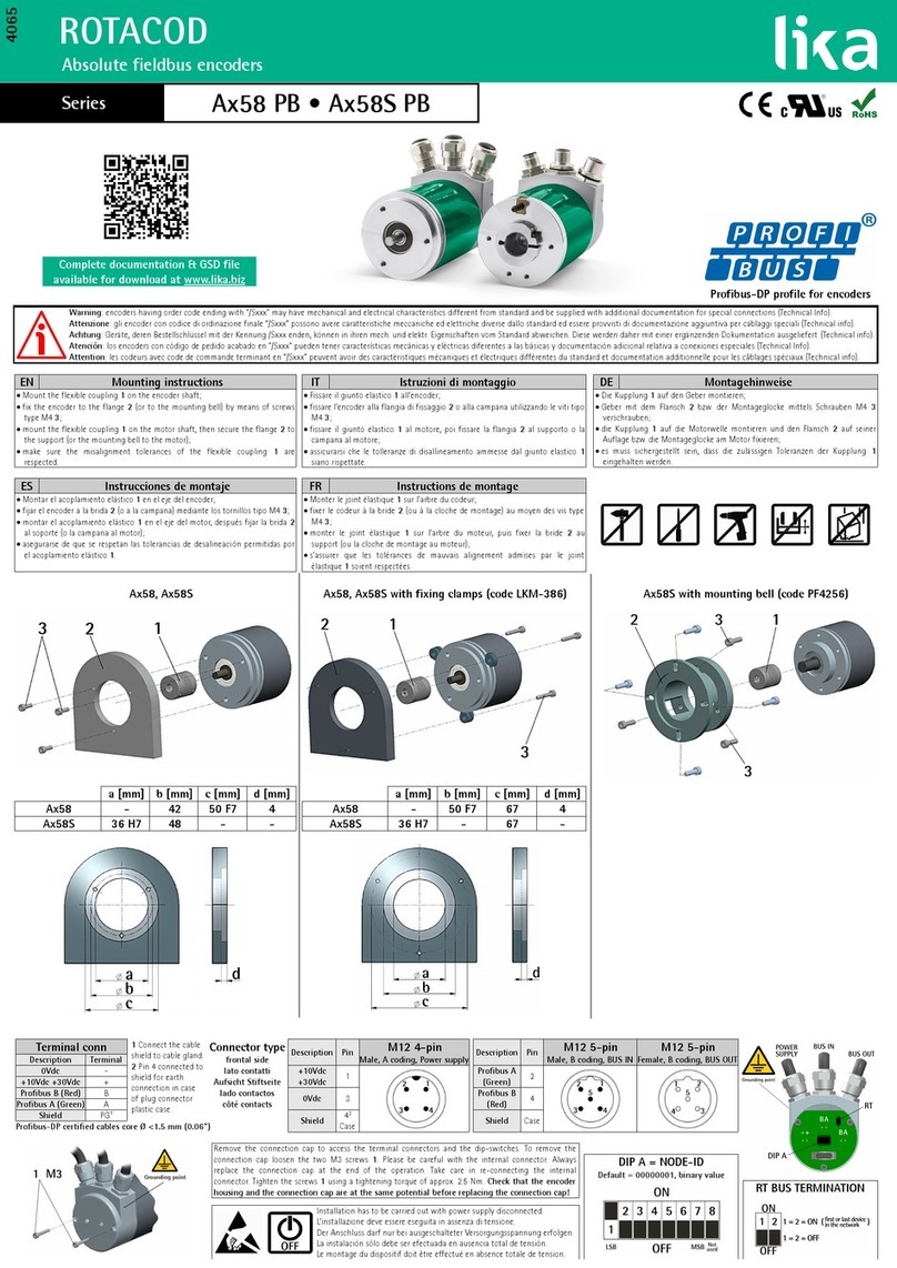
3.1 Encoder with solid shaft EM58, EM58S
•Mount the lexible coupling 1 on the encoder sha t;
•ix the encoder to the lange 2 (or to the mounting bell) by means o the
screws 3;
•secure the lange 2 to the support (or the mounting bell to the motor);
•mount the lexible coupling 1 on the motor sha t;
•make sure the misalignment tolerances o the lexible coupling 1 are
respected.
3.1.1 Customary installation
a
[mm]
b
[mm]
c
[mm]
d
[mm]
EM58 PA - 42 50 F7 4
EM58S PA 36 H7 48 - -
MAN EM58 PA E 1.1 Mechanical installation 12 o 60
EM58 PA
3.1.2 Installation using fixing clamps (optional kit code LKM-386)
a
[mm]
b
[mm]
c
[mm]
d
[mm]
EM58 PA - 50 F7 67 4
EM58S PA 36 H7 - 67 -
3.1.3 Installation using a mounting bell (optional kit code PF4256)
NOTE
In order to guarantee reliability over time o the encoder mechanical parts, we
recommend a lexible coupling to be installed between the encoder and the
motor sha t. Make sure the misalignment tolerances o the lexible coupling are
respected.
MAN EM58 PA E 1.1 Mechanical installation 13 o 60
EM58 PA
3.2 Encoder with hollow shaft
3.2.1 EMC58 PA installation using the antirotation pin
•Fasten the anti-rotation pin 1 to the rear o the motor (secure it using a
locknut);
•mount the encoder on the motor sha t using the reducing sleeve 8 (i
supplied). Avoid orcing the encoder sha t;
•insert the anti-rotation pin 1 into the slot on the lange o the encoder; this
secures it in place by grub screw 2, preset at Lika;
•ix the collar 3 to the encoder sha t.
A = min. 8, max. 18 mm
MAN EM58 PA E 1.1 Mechanical installation 14 o 60
EM58 PA
3.2.2 EMC59 PA installation using the fixing plate
•Remove the antirotation pin 1 (see the Figure in the previous page);
•mount the encoder on the motor sha t using the reducing sleeve 8 (i
supplied). Avoid orcing the encoder sha t;
•asten the ixing plate 4 to the rear o the motor using two M3 x 8 cylindrical
head screws 5;
•ix the collar 3 to the encoder sha t.
A = min. 8, max. 18 mm
MAN EM58 PA E 1.1 Mechanical installation 15 o 60
EM58 PA
3.2.3 EMC6 PA installation using the antirotation pin and the fixing
plate
•Remove the antirotation pin 1 (see the Figure on page 14);
•ix the tempered pin 6 to the rear o the motor;
•mount the encoder on the motor sha t using the reducing sleeve 8 (i
supplied). Avoid orcing the encoder sha t;
•make sure the anti-rotation pin 6 is inserted properly into the ixing plate 7;
•ix the collar 3 to the encoder sha t.
A = min. 8, max. 18 mm
NOTE
You are strongly advised not to carry out any mechanical operations (drilling,
milling, etc.) on the encoder sha t. This could cause serious damages to the
internal parts and an immediate warranty loss. Please contact our technical
personnel or the complete availability o "custom made" sha ts.
MAN EM58 PA E 1.1 Mechanical installation 16 o 60
EM58 PA
4 Electrical connection
WARNING
Electrical connection has to be carried out by quali ied personnel only, with
power supply disconnected and mechanical parts compulsorily in stop.
WARNING
I wires o unused signals come in contact, irreparable damage could be caused
to the device. Thus they must be cut at di erent lengths and insulated
singularly.
4.1 Cable and connectors connections
Function T12 cable M23H 12-pin M12 12-pin
TD RS-232 Red 1 11
RD RS-232 Green 2 9
Fault Yellow 3 4
Vdc RS-232 Brown 4 10
+Iout Grey 5 5
Vdc analogue Violet 6 3
+Vout Pink 7 6
Counting direction Blue 8 8
Preset White 9 7
Not connected Black 10 12
+13Vdc +3 Vdc Brown_Green 11 2
Vdc Power Supply White_Green 12 1
Shield Shield Case Case
4.2 T12 cable specifications
Model : LIKA T12 cable
Cross section : 4 x 0.25 mm2 + 4 x 2 x 0.14 mm2 twisted pairs (24/26 AWG)
Jacket : TPU, extra lexible
Shield : tinned copper braid, coverage > 85%
Outer diameter : Ø 6.1 mm ±0.1 mm (Ø 0.24” ±0.004”)
Min. bending radius : ix min. 25 mm (0.98”) / dynamic min. 45 mm (1.77”)
Work temperature : ix -40 +90°C (-40 +194°F) / dyn -50 +90°C (-58 +194°F)
Conductor resistance : < 148 /km - < 90 /km
MAN EM58 PA E 1.1 Electrical connection 17 o 60
EM58 PA
4.3 M23H 12-pin (counter-clockwise) connector specifications
M23H 12-pin connector
Male
Counter-clockwise
4.4 M12 12-pin connector specifications
Male
Frontal side
A coding
4.5 Connection of the shield
For signals transmission always use shielded cables. The cable shielding must be
connected properly to the metal ring nut 3 o the connector in order to ensure
a good earthing through the rame o the device. To do this disentangle and
shorten the shielding 1 and then bend it over the part 2; inally place the ring
nut 3 o the connector. Be sure that the shielding 1 is in tight contact with the
ring nut 3.
MAN EM58 PA E 1.1 Electrical connection 18 o 60
EM58 PA
4.6 Ground connection
Minimize noise by connecting the shield and/or the connector housing and/or
the rame to ground. Make sure that ground is not a ected by noise. The
connection point to ground can be situated both on the device side and on
user’s side. The best solution to minimize the inter erence must be carried out by
the user. You are advised to provide the ground connection as close as possible
to the encoder.
4.7 RS-232 serial connection
EM58 PA programmable encoder is equipped with a serial inter ace or the
parametrization and set up o the device. A so tware tool is designed to program
the encoder via RS-232 inter ace, it is available at our website. Be ore starting
the program, connect the device to the personal computer through a serial port.
Should the personal computer not be equipped with a serial port, you must
install a USB / RS-232 converter, easily available in the market.
The serial cable must be connected as shown in the table herea ter. See also the
“4.1 Cable and connectors connections” section on page 17.
Function T12
cable
M23 12-pin M12 12-pin
DSub 9-pin
male
Function
TD Red 1 11 2 RD
RD Green 2 9 3 TD
0Vdc Brown 4 10 5 0Vdc
Please always make sure that the RD o the ENCODER is cross-wired to the TD o
the PC while the TD is cross-wired to the RD.
An optional kit itted with RS-232/USB adapter or the communication between
the encoder and the PC is available.
The order codes are as ollows:
•IF92 converter
+
•EC-CR12F-S68-I5- ,5 M23H / USB mating cordset
or
•EC-M12F12-S69-I5- ,5 M12 / USB mating cordset.
MAN EM58 PA E 1.1 Electrical connection 19 o 60
EM58 PA
NOTE
Encoders with T12 cable output require IF92 converter only.
Please note that the con iguration parameters o the serial port have ixed
values so the user cannot change them.
They are:
RS-232 serial port settings Value
Baud rate 9600
Byte size 8
Parity None
Stop bits 1
Flow control None
4.8 Vdc
0Vdc RS-232, 0Vdc analogue and 0Vdc Power Supply are internally connected.
4.9 Fault output
This output is only available i the current output is enabled (Output type =
CURRENT). It is intended to signal an error such as a circuit break. As soon as the
Fault signal is activated, a message is also invoked to appear in the
DIAGNOSTICS box o the CONFIGURATION page (see the error message
Disconnected cable).
To connect the Fault signal please re er to the examples herea ter: “4.9.1 Fault
output connected to a PLC input“ and “4.9.2 Fault output connected to a relay“.
Please pay attention to the value o the R2 resistor (Figure 2 and Figure 3).
Imax = 50 mA
R1 = 47 
R1
I
Vdc
R2








No encoder error = transistor ON (conducting)
Encoder error = transistor OFF (open)
MAN EM58 PA E 1.1 Electrical connection 20 o 60

This manual suits for next models

6

Other Lika Media Converter manuals

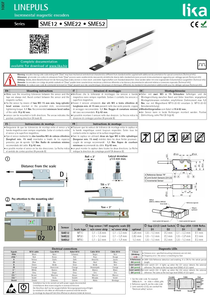
Lika Linepuls SME22 Series User manual

Lika

Lika Linepuls SME22 Series User manual

Lika HS58 User manual

Lika

Lika HS58 User manual

Lika ROTACOD AxC58 CB Series User manual

Lika

Lika ROTACOD AxC58 CB Series User manual

Lika ES58 Series User manual

Lika

Lika ES58 Series User manual

Lika AMM5A / BG1 Series User manual

Lika

Lika AMM5A / BG1 Series User manual

Lika HMC59 User manual

Lika

Lika HMC59 User manual

Lika AMM8A User manual

Lika

Lika AMM8A User manual

Lika ROTAPULS CH59 Series User manual

Lika

Lika ROTAPULS CH59 Series User manual

Lika Posicontrol IF55 LIN CB Series User manual

Lika

Lika Posicontrol IF55 LIN CB Series User manual

Lika LINEPULS SMIG Series User manual

Lika

Lika LINEPULS SMIG Series User manual

Lika SMRI2 User manual

Lika

Lika SMRI2 User manual

Lika Linepuls SME12 Series User manual

Lika

Lika Linepuls SME12 Series User manual

Lika Posicontrol IF55 LIN CB Series User manual

Lika

Lika Posicontrol IF55 LIN CB Series User manual

Lika ES5812/MB Series User manual

Lika

Lika ES5812/MB Series User manual

Lika Posicontrol IF55 LIN CB Series User manual

Lika

Lika Posicontrol IF55 LIN CB Series User manual

Lika CB62 User manual

Lika

Lika CB62 User manual

Lika Posicontrol IF55 LIN CB Series User manual

Lika

Lika Posicontrol IF55 LIN CB Series User manual

Lika ROTAPULS I58S User manual

Lika

Lika ROTAPULS I58S User manual

Lika IP58S User manual

Lika

Lika IP58S User manual

Lika ROTAMAG SMRIL Plus MRI Series User manual

Lika

Lika ROTAMAG SMRIL Plus MRI Series User manual

Lika ROTACOD SMRA Series User manual

Lika

Lika ROTACOD SMRA Series User manual

Lika DRAW WIRE SFES1 Series User manual

Lika

Lika DRAW WIRE SFES1 Series User manual

Lika IP58 User manual

Lika

Lika IP58 User manual

Lika SFA-5000-FD User manual

Lika

Lika SFA-5000-FD User manual

Popular Media Converter manuals by other brands

Jay's Audio DAC2-MK3 user manual

Jay's Audio

Jay's Audio DAC2-MK3 user manual

GRASS VALLEY K2 BASECAMP EXPRESS quick start guide

GRASS VALLEY

GRASS VALLEY K2 BASECAMP EXPRESS quick start guide

Clarion DVH940 owner's manual

Clarion

Clarion DVH940 owner's manual

IS5 COMMUNICATIONS iPS2 quick start guide

IS5 COMMUNICATIONS

IS5 COMMUNICATIONS iPS2 quick start guide

birddog STRP12050A-WIFIRT instructions

birddog

birddog STRP12050A-WIFIRT instructions

Vitec Multimedia MGW user manual

Vitec Multimedia

Vitec Multimedia MGW user manual

ADF Web HD67948-2-A1 user manual

ADF Web

ADF Web HD67948-2-A1 user manual

RGBlink Q16pro-2 user manual

RGBlink

RGBlink Q16pro-2 user manual

MultiDyne HD-3000 Series instruction manual

MultiDyne

MultiDyne HD-3000 Series instruction manual

Siko WV5800M user manual

Siko

Siko WV5800M user manual

Husqvarna CF 11M Operator's manual

Husqvarna

Husqvarna CF 11M Operator's manual

Reliance electric 1203-USB instruction manual

Reliance electric

Reliance electric 1203-USB instruction manual

Kramer VW-16 quick start guide

Kramer

Kramer VW-16 quick start guide

Onbon OVP-H8X user manual

Onbon

Onbon OVP-H8X user manual

Texas Instruments TPS61092 instruction manual

Texas Instruments

Texas Instruments TPS61092 instruction manual

Coosis HDuniversal HU-H user manual

Coosis

Coosis HDuniversal HU-H user manual

M-system 18JV instruction manual

M-system

M-system 18JV instruction manual

DRAKE DDC864A manual

DRAKE

DRAKE DDC864A manual

manuals.online logo
manuals.online logoBrands
  • About & Mission
  • Contact us
  • Privacy Policy
  • Terms and Conditions

Copyright 2025 Manuals.Online. All Rights Reserved.