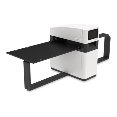
iM3 CR 8 VET Guide

Page 1 of 4
Inlet Guide Replacement Kit
Part Number: IC0118
Replacement Instructions
Introduction. This document provides the instructions necessary to replace the Inlet Guide of a CR 8 VET system. Make
sure to read this entire document before proceeding with any service.
The following information is supplementary to the device installation and operating instructions.
As a general rule, the installation and operating instructions for the device must also be observed. These instructions
include important information such as safety instructions and information on the setup, electrical connections, disinfection
process, cleaning process, etc.
Any repairs above and beyond routine maintenance must only be carried out by suitably qualified personnel.
Scope of Delivery. The following items are included in the scope of delivery:
– Inlet Guide (Qty 1)
– M3 X 8 Socket Head Cap Screws (Qty 10)
Required Tools (not supplied).
– 2.5 mm Allen wrench
– 5 mm flat-head screwdriver
NOTICE
Electrostatic-sensitive devices on the
assemblies
iAlways switch off the operating voltage before
carrying out any assembly or installation work on
the device.
iBefore and during the installation or assembly
work on the device, always ensure that the person
carrying out the work is grounded.
Before working on the appliance or in case of
danger, disconnect it from the mains (e. g. pull the
mains plug).
Task Guidelines. Personnel performing the replacement tasks should use standard industry guidelines for working
on equipment. These include the following:
iAlways use a clean well-lit work area with ample space required for the size of the job.
iObserve all warnings and precautions for safety as shown by the labels placed on the equipment. Keep all attaching
hardware and fastening screws together with the associated removed assembly.
iIf necessary use separate storage containers or envelopes for each hardware group.
iPrior to removing any part or assembly, note location and orientation of assemblies being removed.
iTag wires and associated mating connectors before disconnecting.
iUse care when disconnecting mating connectors so as not to damage the connector keys and connection to
the associated printed circuit board, wire or cable.
iBe aware of the damage impact of electrostatic discharge (ESD) on electronic devices and use ESD precautions
when handling printed circuit boards and wiring.
iDo not lift or move the unit by the top Touchscreen Assembly.
iOnly llift the unit by the sides of the Transport Assembly and/or the bottom base.
(J1650)
Image Plate Scanner

Page 2 of 4
Removal Procedures
Removing the Inlet Guide. Refer to Figure 1 and remove the Inlet Guide as follows:
1. Remove the SDHC card and the Access Cover.
2. Unplug the power supply, communication cable, and Wi-Fi adapter.
3. Remove the Rear Cover by removing the two screws located at the lower back of the unit. Lift at the bottom and
then pull off.
4. Disconnect the multi-color harness located at the top of the Main Circuit Board.
5. Remove top left Main Circuit Board screw connecting the (green) ground wire to the board.
6. Remove the Inlet Guide with the Touchscreen Assembly attached by removing the 4 upper screws (2 each side)
located on the back of the unit.
CAUTION
Risk of Touchscreen Damage
iPlace soft dry cloth on bench to protect Touchscreen when setting
screen side down on the work area.
7. Once the Inlet Guide with the Touchscreen Assembly attached has been removed, flip it over to detach the
Touchscreen Assembly.
8. Remove the Touchscreen Assembly, by removing the three securing screws and sliding the two assemblies
apart. Discard the Inlet Guide to be replaced.
Power Removal. Prior to performing the procedures contained in this document, turn off power by disconnecting the line
cord from the wall outlet.
CAUTION
Risk of damage to unit as a result of improper handling.
iDo not move the unit during operation.
iDo not lift or move the unit by the top Touchscreen Assembly.
iOnly llift the unit by the sides of the Transport Assembly and/or the bottom base.
Figure 1. Inlet Guide Removal
Rear Cover
securing screws
Main
Circuit
Board
Inlet Guide
securing screws
(2 each side)
Inlet Guide
Touch-
screen
Assembly
1
3
2
SDHC
card
Access
Cover
Ground
Connection Touchscreen
Main Circuit
Board
Connections

Page 3 of 4
Re-Assembly Procedures
Installing the Inlet Guide. Refer to Figure 2 and install the Inlet Guide as follows:
CAUTION
Risk Wiring Damage
iMake sure to feed all of the wires from the Touchscreen Assembly
through the center hole of the replacement Inlet Guide.
iMake sure all Main board wires are properly connected.
iMake sure not to kink or damage wiring.
1. Install the replacement Inlet Guide onto the Touchscreen Assembly by lining up the pegs from the Touchscreen
Assembly with the holes in the Inlet Guide and sliding them into place. Secure with the three securing screws.
2. Making sure to engage the front lip of the Inlet Guide into the groove on the Upper Roller Housing, install the Inlet
Guide with the Touchscreen Assembly attached by securing the 4 upper screws (2 each side) located on the
back of the unit.
3. Install the top left Main Circuit Board screw connecting the (green) ground wire to the board.
4. Connect the multi-color harness located at the top of the Main Circuit Board.
5. Place the Rear Cover onto the unit, inserting the three points on the top of the Rear Cover into the slots on the
bottom of the Touchscreen Assembly.
6. Secure the Rear Cover to the unit using the two screws installed at the lower portion of the cover as shown.
7. Plug in the power cable, communication cable, and Wi-Fi adapter. Install the SDHC card and the Access Cover.
Figure 2. Inlet Guide Installation
Rear Cover
securing screws
Main
Circuit
Board
Inlet Guide
securing screws
(2 each side)
Inlet Guide
Touch-
screen
assembly
1
32
SDHC
card
Access
Cover
Ground
Connection
Touchscreen
Main Circuit
Board
Connections

Page 4 of 4
Check Scanner Operation. Check the scanner operation with the replacement Inlet Guide by performing the following
steps:
1. Reconnect the power supply to the wall outlet.
2. Turn the unit power ON.
3. Initialize the unit for scanning normal images using the user’s imaging software.
4. Refer to the Operator’s Manual and perform a scan operation of one (or more) sample image using any
reasonable image exposure.
5. If the unit operates normally and the scanned image appears nominal, return the unit to user operation.
Recommissioning Procedures
© 2022 Air Techniques, Inc. •P/N J1633-LIT Rev. A •April 2022
Manufactured By:
Air Techniques, Inc. 1295 Walt Whitman Road
Melville, New York, USA 11747- 3062
Phone: 800-247-8324 |Fax: 888-247-8481
This manual suits for next models
1
Table of contents
