i
i15
i
i
To help you make informed decisions about safety, you
will nd important safety information in a variety of forms,
including:
• Safety Labels on the post driver
• Safety Messages Preceded by a safety alert
symbol and one of three signal words, DANGER,
WARNING, or CAUTION. These signal words mean:
Immediate hazards that will result in
severe personal injury or death.
Hazards or unsafe practices that could
result in personal injury.
Hazards or unsafe practices that could
result in injury, product or property
damage.
• Safety Headings such as IMPORTANT SAFETY
INFORMATION.
• Safety Section such as POST DRIVER SAFETY.
• Instructions how to use this post driver correctly
and safely.
TAKE SAFETY SERIOUSLY TROUBLE SHOOTING
15
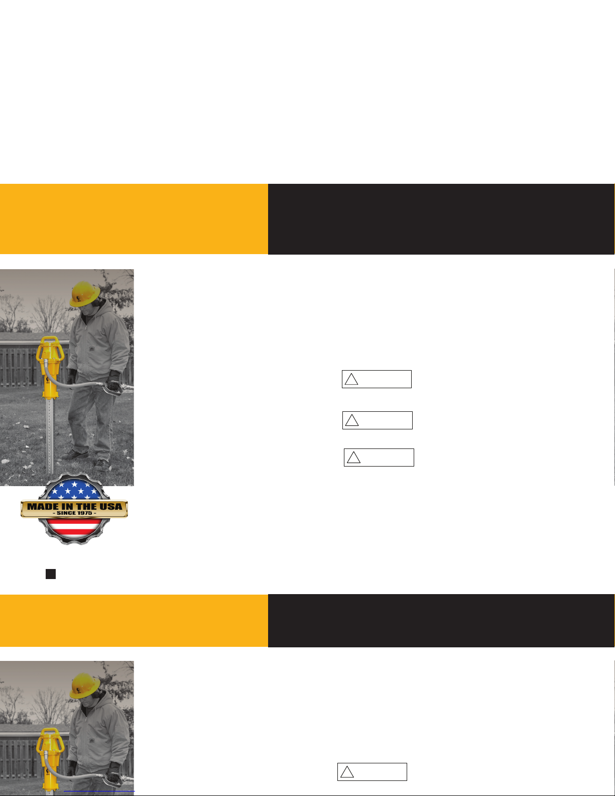
Your safety, and the safety of oth-
ers, is very important. The proper
and safe use of your Rhino® post
driver is an important responsibility
and should be taken seriously.
Keep this owner’s manual avail-
able, so you can refer to it at
any time. This owner’s manual is
considered a permanent part of the
post driver and should remain with
the post driver if resold.
The information and specications
included in this publication were
in eect at the time of approval
for printing. Rhino Tool Company,
Inc. reserves the right, however,
to discontinue or change
specications or design at any time
without notice and without incurring
any obligation whatever. No part of
this publication may be reproduced
without written permission from:
Rhino Tool Company
!DANGER
!CAUTION
IMPORTANT
NOTE
This book contains important safety information.
Please read it carefully.
Call your local dealer, service center or Rhino Tool
Company for more assistance with your post driver
i
To help you make informed decisions about safety, you
will nd important safety information in a variety of forms,
including:
• Safety Labels on the post driver
• Safety Messages Preceded by a safety alert
symbol and one of three signal words, DANGER,
WARNING, or CAUTION. These signal words mean:
Immediate hazards that will result in
severe personal injury or death.
Hazards or unsafe practices that could
result in personal injury.
Hazards or unsafe practices that could
result in injury, product or property
damage.
• Safety Headings such as IMPORTANT SAFETY
INFORMATION.
• Safety Section such as POST DRIVER SAFETY.
• Instructions how to use this post driver correctly
and safely.
TAKE SAFETY SERIOUSLY TROUBLE SHOOTING
!DANGER
!CAUTION
IMPORTANT
NOTE
This book contains important safety information.
Please read it carefully.
Call your local dealer, service center or Rhino Tool
Company for more assistance with your post driver
Symptom Explanation/Procedure
Post lodged in the
driver
1. Remove the 2 bolts that secure the adapter and separate the driver from the adapter.
2. Slide the adapter down the post to expose the top of the post. With the proper cutting tool for the type of post, cut
through the post below the ared portion.
3. Once the deformed portion is removed, slide the adapter off the post and reassemble it to the driver. Please follow
bolt tightening procedure.
Drives post slow
or sluggish
performance
1. Inspect the chuck to see if there is any foreign material blocking the piston.
2. Check to see if piston is moving freely by disconnecting the driver from air, tipping upside down and back upright.
You should be able to hear the piston moving freely.
3. Check to ensure the rate of lubrication is adequate.
4. If using a FRL, inspect the lter on the FRL, if impacted with residue replace with new lter.
5. Inspect the lter on the Throttle. If clogged, blow off debris with air hose, or clean with a common cleaning solvent.
6. Check to see if air pressure is correct
7. Check output on compressor
8. In temperatures under 40ºF (4ºC) or high humidity conditions check air lines and tool for icing.
Noticeable air passing
through driver or
“blow by”
To conrm this condition exists, connected to air source, place driver on a post, while activating the throttle lift the
driver slightly if the piston increases in activity blow by is conrmed. This indicates there is most likely damaged or
worn parts inside the driver. In this event the driver should be sent to Rhino Tool Company to be inspected and we
will report if the driver is repairable.
Other problems or
technical questions
Other problems or technical questions: Document your serial number and contact Rhino Tool Company. Phone:
309.853.5555 or Toll Free 866-707-1808, Fax:309.856.5905, Email: [email protected]. In Europe contact Eurogate Int. F: (0031) (0) 523 638286, M: (0031) (0) 610 502607.
© 2013, 2015, 2017 Rhino Tool Company Inc., - All Rights Reserved
© 2013, 2015, 2017 Rhino Tool Company Inc., - All Rights Reserved