ImageTech MCU4 User manual

MCU 4
S0 S1 S2 S3 S4M
RESERVE
SLAVE
1234 0
+
-G
SOURCE
OUTPUTINPUT
INDIVIDUAL
1 2 1 2
PAIR
CONSOLE
S0S1S2S3S4
1 2 3 4 5 6 128 117 9 10
I/O Port & LED
Packing:
iMageTech MCU4 Wireless Meeting Speakerphone System
Start
iMageTech MCU4 unit USB cable USB adapter Terminal port
(16pin+12pin)
VCS cable set
(Differs according to VCS model)
Step1 : Connect the USB adapter (No.12) to the iMageTech MCU 4 Wireless Meeting Speakerphone System.
Step2 : Press the “Bluetooth Speakerphone pairing button (No.8)” on the back for 3 seconds, and wait until “the Bluetooth connection status indicator
(blue)” rapidly flashes, then it can automatically be mapped to the iMage A1/A2 Bluetooth Conference Speakerphone. Simply pair five sets of
iMage A1/A2 Bluetooth Conference Speakerphones to S0, S1, S2, S3 and S4 in order (make sure that the iMage A1/A2 Bluetooth Conference
Speakerphone is set to “Adpter mode” before pairing).
Step3 : Select audio source (Bluetooth, USB or video mode). You can select Bluetooth to connect mobile devices or USB devices to the computer, or connect
a VCS using dedicated audio cables. If Bluetooth audio source is selected, please pair it using the Bluetooth audio source pairing button (No.10).
1. Power indicator
2. Audio source status indicator
(Bluetooth/blue, USB/red, VCS/none)
3. Bluetooth connection status indicator (Blue)
4. System-reserved port
5. Audio Out (independent audio output)
6. Audio In (connect to Audio Out of the VCS)
7. Audio Out (connect to the Audio In of the
VCS)
8. Bluetooth Speakerphone pairing button (S0,
S1, S2, S3, S4)
9. Console pairing button
10. Bluetooth audio source pairing button
11. Audio source selection switch (video, USB, Bluetooth)
12. USB power
Source
The iMageTech MCU4 Wireless Meeting Speakerphone System can quickly connect to the audio device you require through the “audio source
selection switch (No.11)”; it provides three connection modes: Bluetooth, USB and VCS.
*Bluetooth mode: Press and hold the “Bluetooth audio source pairing button (No.10)”for 3 seconds to enter pairing mode to pair and use the
device.
*USB mode: Simply connect the PC and the iMageTech MCU4 Wireless Meeting Speakerphone System with a USB cable.
*VCS mode: Please refer to the chapters “Connecting VCS” and “Wiring method”.
Specification
Notes
Statement
Contact Us! Need more help? Please contact us now
LED Indicator Bluetooth connection status display
*This product must be used with iMage A1/A2 Bluetooth Conference Speakerphone and be set up by professional engineers before it can be used; please contact an engineer if you encounter any problems during use.
*When connecting with iMage A1/A2 Bluetooth Conference Speakerphone, the maximum distance allowed between the two is approximately 10 meters provided that there are no large objects (such as walls etc) or barriers
in between them.
*iMageTech MCU4 Wireless Meeting Speakerphone System can be paired with a maximum of 5 iMage A1/A2 Bluetooth Conference Speakerphones. Please be careful to only pair one speakerphone at a time; when one
speakerphone is successfully paired with the system, then proceed to pair the next one.
*If you are pairing your iMageTech MCU4 Wireless Meeting Speakerphone System and iMage A1/A2 Bluetooth Conference Speakerphone for the first time, it takes approximately 30~45 seconds to complete the pairing
process; but if you have previously paired them before, pairing can be completed in approximately 10 seconds.
This product complies with the provisions of the low-power radio wave radiation Administrative Regulations Article XII-XIV etc.
*Without permission granted by the DGT, any company, enterprise, or user is not allowed to change frequency, enhance transmitting power or alter original characteristic as well as performance to an approved low power
radio-frequency devices.
*The low power radio-frequency devices shall not influence aircraft security and interfere legal communications; If found, the user shall cease operating immediately until no interference is achieved.
*The said legal communications means radio communications is operated in compliance with the Telecommunications Act.
*The low power radio-frequency devices must be susceptible with the interference from legal communications or ISM radio wave radiated devices.
1. Website Introduction: http://www.iMagetech.com.tw (provides the newest support information and online user manual)
2. E-mail address: http://www.iMagetech.com.tw/contact.php
3. Please call: 886-2-27967771
4. Address 5F., No.16, Ln.15, Sec. 6, Minquan E. Rd., Neihu Dist., Taipei City 114
The current connection status can be determined by how the “Bluetooth
connection status indicator (blue)” flash:
*Entering pairing mode: Flash rapidly
*Pairing successful: Light remains constantly
*Flash once every 5 seconds: No devices to pair
*Note: The data listed above were acquired by laboratory testing; actual data may vary according to different usage scenarios.
Model:
iMageTech_MCU4_03
Dimensions:
265mm X 127mm X 44.5mm
Weight:
445±5g
Bluetooth Version:
Bluetooth v3.0+EDR/AGHFP V1.6
Operating Frequency:
2402MHz~2480MHz
Module Type:
Bluetooth Specification V3.0 Class 2 and Class 3
Audio Input/Output Type:
Bluetooth/Terminal/USB
Audio Performance:
Sample rate: 16K
Crosstalk: 75dB
SNR: 85dB
Audio Mixer:
5 channel analog in/out
Audio Input:
MIC in/Line In
Impedance: < 10 KΩ
Maximum Level: 0 dB
Audio Output:
Impedance: > 600 Ω
Maximum Level: 0 dB
Individual Audio Output:
Impedance: > 600 Ω
Maximum Level: 0 dB
Configuration & Admin Software:
iMageTech Audio Parameter Editor....TBD
Control Ports:
Serial Command Protocol Only (Console
software not supported on RS- 232 port)
DB-9 female - Reserve
38,400 baud rate; 8 bits,1 stop bit, no parity
USB:
Mini-USB Type B
Antenna Type:
Build-in Antenna
Power:
DC5v ±10%
Operating Temperature:
0 ~ 60℃
Optional Accessories:
iMage A1/A2 Bluetooth Conference Speakerphone
PSTN/SIP Moduel
Dial Pad

iMageTech MCU4 Advanced settings
VCS wiring instructions (Cisco SX20, advision XT series)
VCS cable set is already included in the iMageTech MCU4 Wireless Meeting Speakerphone System product package, allowing you to connect to several frequently used VCS mode (Cisco SX20, Radvision
XT series) directly. The following are the wiring methods and the reference figure for the corresponding pins.
Please note that the wiring of this product must be performed by a professional engineer in order to avoid misconnection resulting in function failure.
RESERVE
SLAVE
1234 0
+G
SOURCE
OUTPUTINPUT
INDIVIDUAL
1 2 1 2
PAIR
CONSOLE
S0S1S2S3S4
RESERVE
SLAVE
1234 0
+
-G
SOURCE
OUTPUTINPUT
INDIVIDUAL
1 2 1 2
PAIR
CONSOLE
S0S1S2S3S4
Connect Cisco to SX20
Audio Out
Connect Cisco to SX20
Audio In
Cisco SX20 Radvision XT series(XT5000, XT4200)
1. Cable required: 1. Cable required:
3.5mm (4-pole) to stripped wire
connector
3.5mm (3-pole) to stripped wire
connector
3.5mm (3-pole) to stripped wire
connector+RCA
3.5mm (3-pole) to stripped wire
connector+RCA
2. Wiring instructions:
Connect the “+ (positive)”and “G (ground)”of the stripped wire connector to the corresponding
iMageTech MCU4 Wireless Meeting Speakerphone System terminal ports; insert the 3.5mm
terminal directly into the Audio In/Out of Cisco SX20.
2. Wiring instructions:
Connect the “+ (positive)”and “G (ground)”of the stripped wire connector to the corresponding
iMageTech MCU4 Wireless Meeting Speakerphone System terminal ports; insert the 3.5mm
terminal directly into the Audio In/Out of Radvision XT series.
Connect Radvision to XT series
Audio Out
Connect Radvision to XT series
Audio In
-
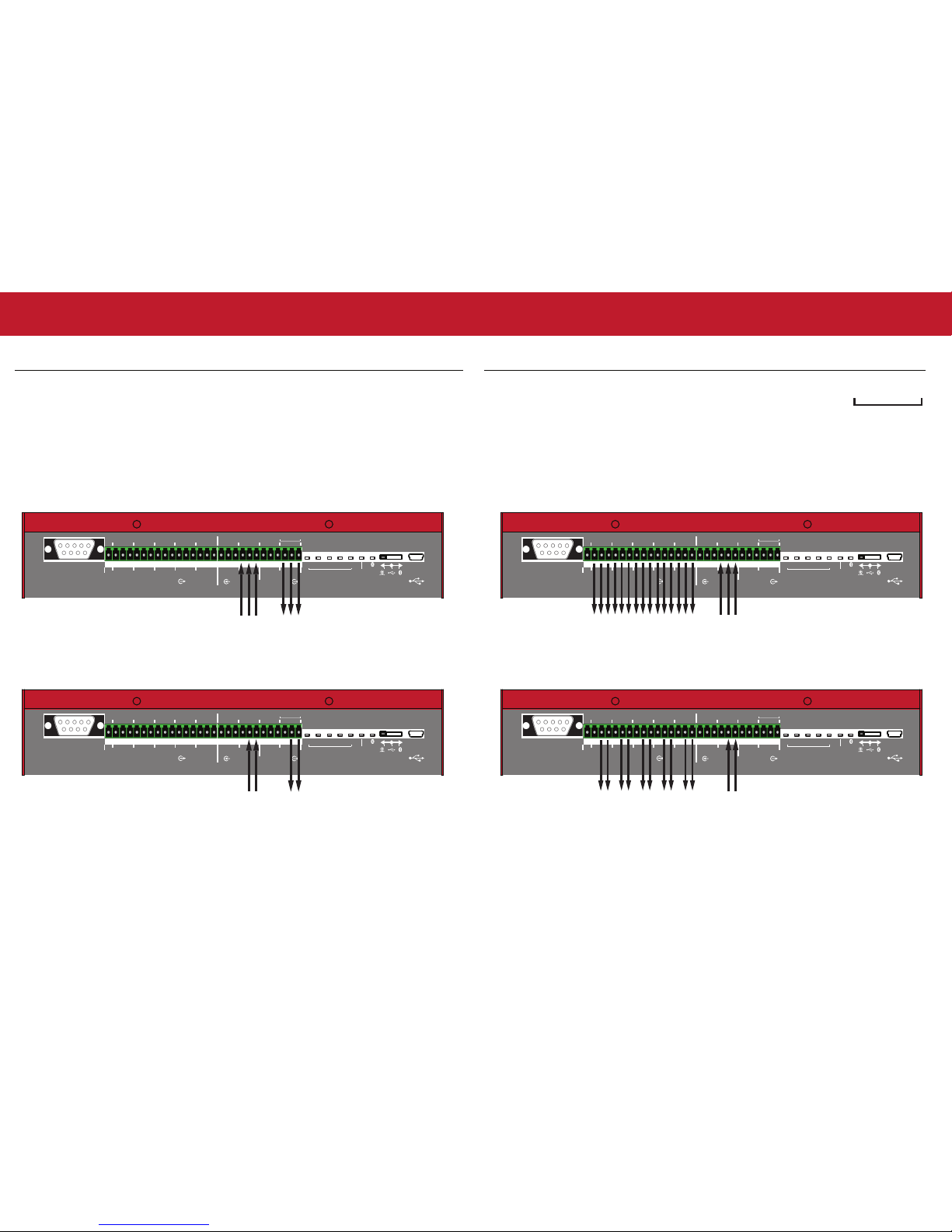
VCS Wiring (other models)
If your VCS is another model, you can still use the following wiring method to connect and use
with the iMageTech MCU4 Wireless Meeting Speakerphone System; the following is the reference
figure for the corresponding wiring pins.
Note! The output/input terminal audio values and standards of different VCS may differ; please
first refer to the user manual of the VCS you want to connect to.
RESERVE
SLAVE
1234 0
+G
SOURCE
OUTPUTINPUT
INDIVIDUAL
1 2 1 2
PAIR
CONSOLE
S0S1S2S3S4
RESERVE
SLAVE
1234 0
+G
SOURCE
OUTPUTINPUT
INDIVIDUAL
1 2 1 2
PAIR
CONSOLE
S0S1S2S3S4
RESERVE
SLAVE
1234 0
+
-G
SOURCE
OUTPUTINPUT
INDIVIDUAL
1 2 1 2
PAIR
CONSOLE
S0S1S2S3S4
RESERVE
SLAVE
1234 0
+
-G
SOURCE
OUTPUTINPUT
INDIVIDUAL
1 2 1 2
PAIR
CONSOLE
S0S1S2S3S4
Balanced connection
+
-G
Terminal connection
When connecting, please note that the order from left to right is negative, positive
and ground respectively.
Connect to VCS
Audio Out
Connect to VCS
Audio In
Connect to VCS
Audio Out
Connect to VCS
Audio In
Unbalanced connection
Independent audio output connection (balanced) (the reception of each iMage A1/A2 Bluetooth
Conference Speakerphone can be output to external audio equipment independently)
Independent audio output connection (unbalanced) (the reception of each iMage A1/A2 Bluetooth
Conference Speakerphone can be output to external audio equipment independently)
Connect to VCS
Audio Out
Connect to external audio equipment or VCS
Audio In
Connect to VCS
Audio Out
Connect to external audio equipment or VCS
Audio In
iMageTech MCU4 Advanced settings
-
-


.
Table of contents
Other ImageTech Telephone manuals


Popular Telephone manuals by other brands


Williams Sound
Williams Sound TeleTalker TEL 040 User's installation guide

Cooper safety
Cooper safety VoCALL CFVCM User manual & log book

NEC
NEC Univerge SV8100 Administrator's manual

Aastra
Aastra 9009 user guide

Uniden
Uniden D1688 Guide d'utilisation

Dolby Laboratories
Dolby Laboratories Conference Phone Configuration guide


