IMC CS-C1 Owner's manual

Installation, Operating and Servicing
Instructions
A34/038 R11 ECN 4825 February 2021
CHIPPER –CS-C1
Please make a note of your product details for
future use:
Date Purchased:_________________________
Model Number:__________________________
Serial Number:__________________________
Dealer:_________________________________
________________________________
_______

CONTENTS
DELIVERY ............................................................................................................1
INTRODUCTION...................................................................................................1
CHIPPER DIMENSIONS.......................................................................................1
INSTALLATION....................................................................................................2
PROCEDURE .......................................................................................................2
ELECTRICITY SUPPLY CONNECTION ..............................................................2
COMMISSIONING ................................................................................................3
OPERATION.........................................................................................................3
KNIFE BLOCK FITTING.......................................................................................4
CHANGE CHIP SIZES..........................................................................................5
CLEANING............................................................................................................5
CHANGING KNIFE BLADES ...............................................................................5
WIRING DIAGRAM FOR CHIPPER .....................................................................7
EXPLODED VIEW ................................................................................................8
ELECTRICAL CONTROL PARTS..................................................................... 9
SPARES LIST.....................................................................................................10
PARTS LIST CONTINUED…..............................................................................11
GUARANTEE......................................................................................................12
SERVICE INFORMATION ..................................................................................13
The packaged machine consists of:
Chipper Unit, Comprising:
1
Hopper
1
Knife Block
1
Main Unit
1
Instruction Booklet
1
Wall Plaque
1
Please notify both the carrier and the supplier within 24 hours of receipt if
anything is missing or damaged.
Check that the correct machine has been supplied and that the voltage, marked
on the rating plate, is suitable for the supply available. The rating plate is
located on the right hand side of the case.
The Chipper is intended for cutting peeled potatoes into chips or scallops, in a
batch process.
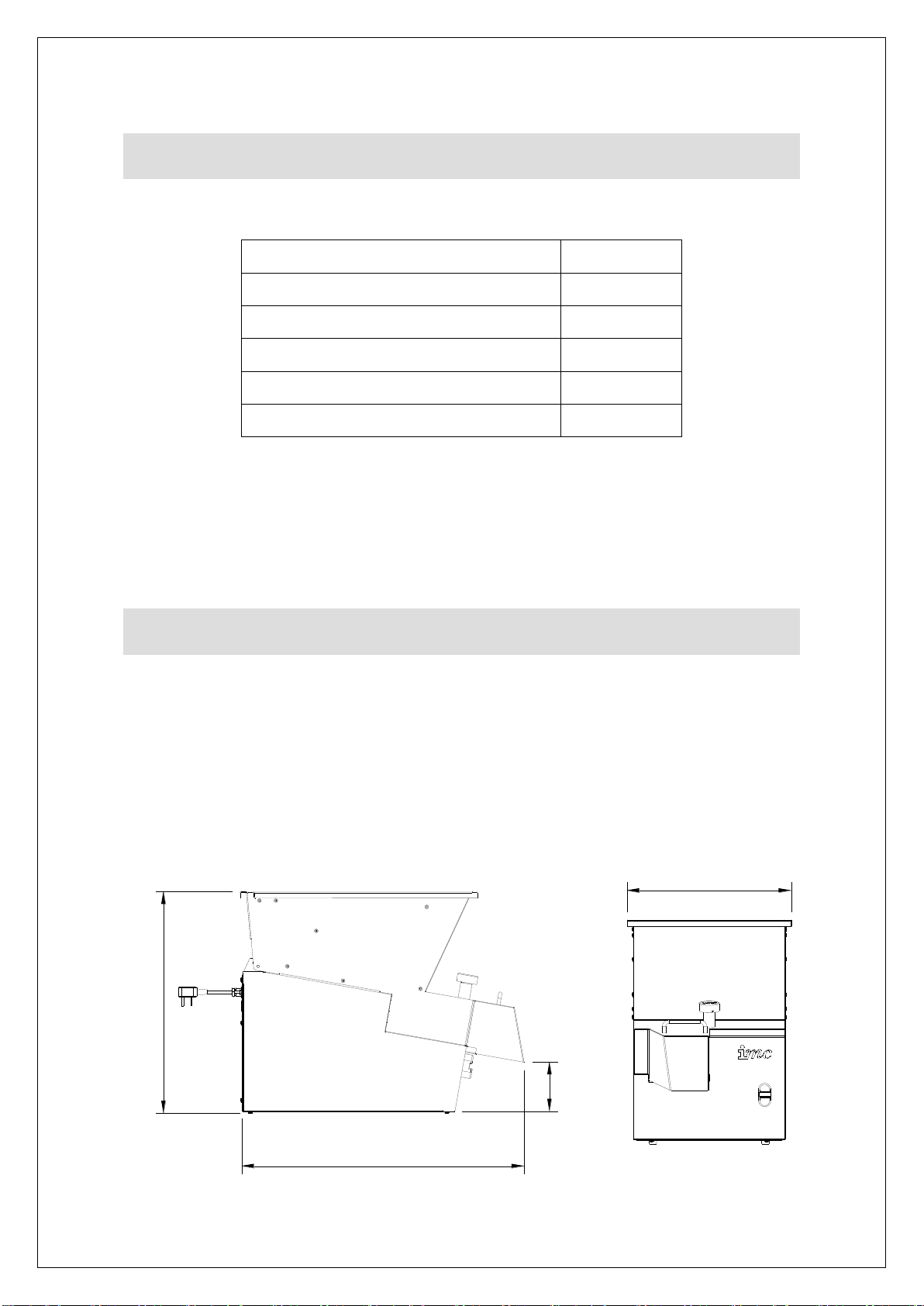
CHIPPER DIMENSIONS
All dimensions are in mm.
690
550
400
120
DELIVERY
INTRODUCTION

For the Installer:
These Instructions contain important information designed to help the user
obtain the maximum benefit from the investment in an IMC Chipper.
Please read them carefully before starting work, and consult with the supplier in
the event of any queries.
Be sure to leave this Instruction Manual with the user after installation of the
machine is complete.
The unit is designed to stand on a bench, table, or on a draining board. Ensure
that whatever is used for this purpose is sturdy and rigid and not more than 750
mm high. A higher table makes it difficult to load the machine.
The Chipper should be placed where supplies of peeled potatoes from the
peeling machine are readily accessible, after which the output of chips need to
be in easy reach of the fryer.
The IMC Chipper has a top loading hopper into which potatoes can be tipped
from either side or from the front. It is not handed, and no consideration need be
given to its loading direction. The discharge of chips is from the chute at the
front of the machine, and the machine should be placed so that this chute is
directly over the receiving container.
A Wiring Diagram is shown on Page 7.
Position the Chipper in the chosen site. The electricity supply connection should
be made to a power outlet socket or isolator mounted on the wall close to the
machine. This socket or isolator must be accessible once the machine is
installed. Before connecting, check that the voltage shown on the rating is
correct for the electricity supply you have available. The outlet should be fused
at 13 amps.
NOTE: The plug is fitted with a 10amp fuse.
WARNING: This machine must be earthed
Should the supply cord become damaged then an approved electrician must fit
a replacement. The IET Codes of Practice must be observed.
INSTALLATION
PROCEDURE
ELECTRICITY SUPPLY CONNECTION

An equipotential bonding terminal is provided at the back of the unit near the
cable outlet for external earth bonding. Provision of an earth bond does not
remove the requirement for an earth in the electrical supply.
Open the hopper by fully unscrewing the interlock knob at the front and lifting up
until the hopper is fully resting back on its hinges. Turn the rotor by hand to
ensure that it is completely free to rotate and that the knife block assembly is
properly in position. Replace the hopper and screw down the interlock knob until
it is tight.
It is now safe to switch on at the wall socket and to start the machine by
pressing the start button on the front of the machine (green button). To stop the
machine press the red button.
One of the safety features provided on the IMC Chipper are the interlock
devices that ensures that the machine cannot run unless both the knife block
and the hopper are properly and fully in position. This makes it impossible for
the operator to touch the spinning rotor whilst it is running.
To confirm that the interlock is operating correctly press the start button to
switch the machine on. Then whilst it is still running, unscrew the hopper
interlock knob. After two or three turns the machine should switch off, but there
are still two or three further turns of the knob necessary before the hopper can
be opened. The rotor should be stationary within 2 seconds of the hopper being
opened. If the knife block is not in place, another interlock will prevent the
machine from running.
With the machine running, feed peeled potatoes into the hopper. It will hold
approximately 15kg of potatoes, which self feed into the mechanism of the
machine and discharge as cut chips from the chute.
Some care is necessary when loading, as the rotor will not accept abnormally
large potatoes, so these must be cut into two. The hopper is specially designed
not to pass potatoes which are over size and which could otherwise clog the
mechanism. It is also essential that only potatoes be fed in to this machine.
NOTE: take great care to ensure that there are no stones mixed in with the
potatoes.
A stone or any other foreign object will damage the cutting knives and could
cause the machine to jam. In this event the machine has an inbuilt protection
device, which will switch it off before the electric motor burns out. This overload
protection feature will automatically reset itself when it cools down but it is
necessary to wait a few minutes for this to happen. After clearing the jam
COMMISSIONING
OPERATION
resume operation by pressing the start button. Should a stone damage the knife
blades they must be replaced as further use could break the blades.
This Chipper is designed for batch process work; switch the machine off once
all the potatoes have been cut. The motor is fitted with a thermal trip that will
stop the machine if the motor overheats. This protection feature will
automatically reset itself when it cools down but it is necessary to wait a few
minutes for this to happen.
The machine will switch itself off in the event of failure of the electricity supply
whilst operating. When the supply is restored the machine must again be
switched on. It is fitted with no-volt release.
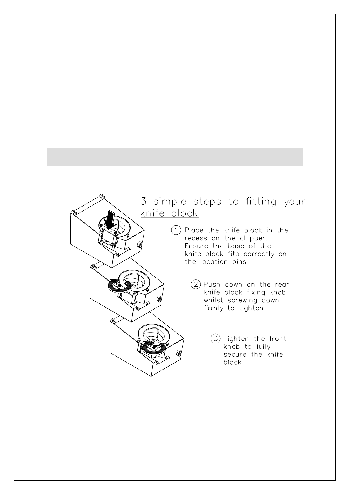
KNIFE BLOCK FITTING

To change to a different size of chip, change the knife block assembly. Spare
knife block assemblies are available from Lincat. Open the hopper, lift out the
knife block and replace with the alternative selected. Knife blocks are available
in the following sizes from the standard range: 12mm, 14mm, 14 x 17mm and
17 x 21mm.
It is essential to clean the machine at least once a day, preferably at the end of
each period of operation.
1. Switch off at the socket or isolator.
2. Fully unscrew the interlock knob, open the hopper and lift it out of its hinge
seating at the back.
3. Clean the hopper in a sink, dishwasher, pot wash or by hosing with a
spray.
4. Remove the knife block by lifting upwards, off its locating dowels
NOTE: Take care when handling the knife block. The blades are
sharp.
5. Clean the knife block under a spray or running tap and remove any
residual pieces of potato. Visually inspect all blades for wear or damage,
and replace the knife pack as necessary. Do not attempt to straighten a
bent blade - bent blades should be replaced immediately.
6. Lift the rotor carefully off its spindle.
7. Clean the rotor in a sink, pot wash, etc.
8. Clean out the interior of the base unit and wipe over the exterior with a
damp soft cloth. Do not hose down the exterior of the machine.
DO NOT USE CLEANING MATERIALS CONTAINING ABRASIVES OR
BLEACHES.
9. Reassemble the machine, reversing the above disassembly procedure.
When replacing the rotor, ensure that it is put back square on its spindle.
Make sure that it is properly seated on its cross pin by turning it slowly until
it drops onto this seating. When replacing the knife block it should slip
down easily on to its dowel pins, make certain that it is fully down.
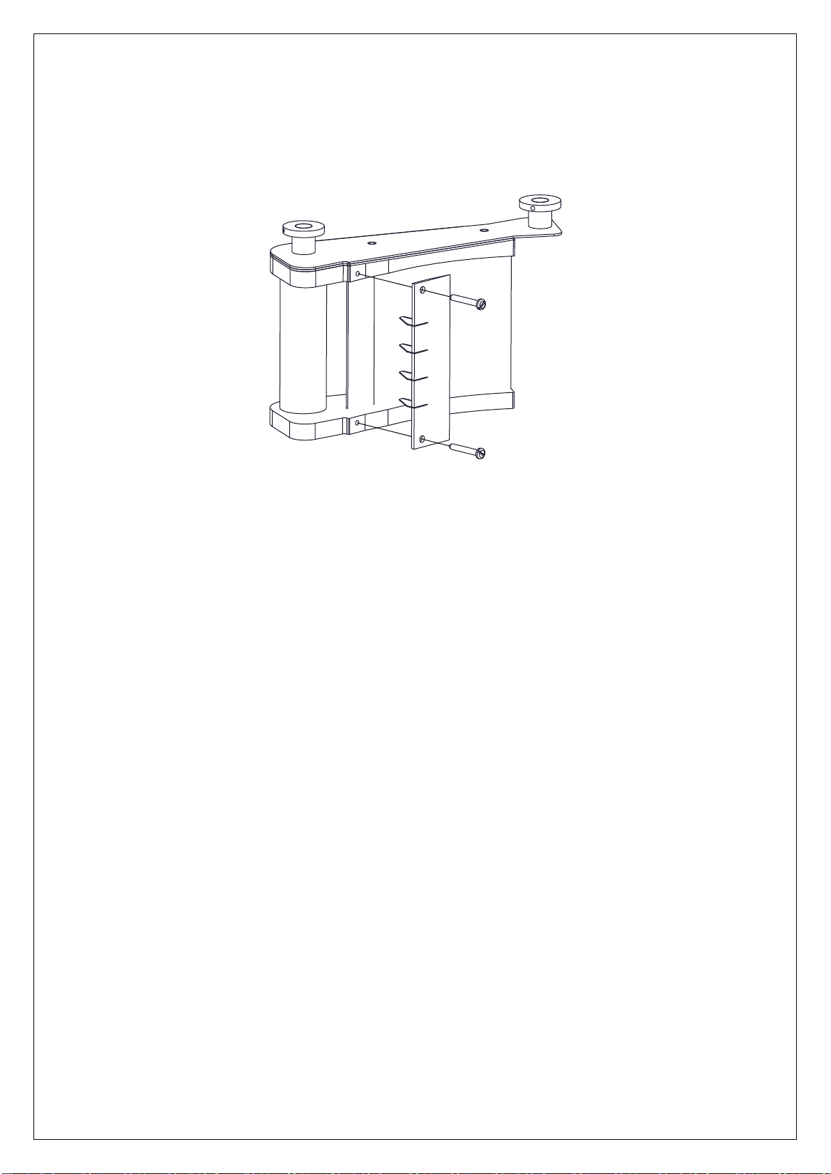
The knife blades are supplied as a pack and individual blades cannot be
changed. Change the knife blade pack as soon as it is damaged or blunt. To
change the knife blade pack remove the knife block and undo the two screws
securing the knife blade pack. Dispose of the old blades carefully and screw the
new knife blade pack in place. See diagram on the next page.
CHANGE CHIP SIZES
CLEANING
CHANGING KNIFE BLADES
For optimum performance Lincat recommend changing the blade pack every 6
months, or sooner depending on usage.
NOTE: Take care when handling the knife block. The blades are sharp.

WIRING DIAGRAM FOR CHIPPER
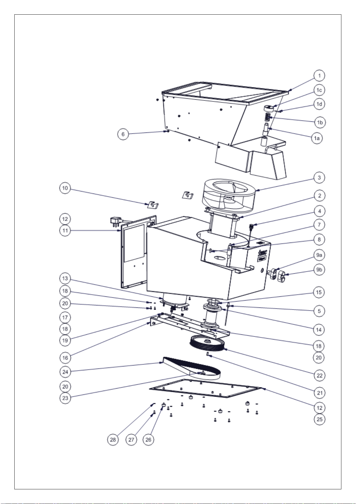
EXPLODED VIEW

ELECTRICAL CONTROL PARTS

ITEM
PART NO
DESCRIPTION
1
S61/150
HOPPER ASSEMBLY, INCORPORATING:
1a
M81A
INTERLOCK BODY & MAGNET
1b
A12/011
INTERLOCK SPRING
1c
L61/024
HOPPER KNOB
1d
D26/017
INTERLOCK PIN
2a
S61/184
21x17mm KNIFE BLOCK
S61/145
12mm KNIFE BLOCK
S61/151
14mm KNIFE BLOCK
S61/144
14x17mm KNIFE BLOCK
2b
S61/183
21x17mm KNIFE PACK ASSY
S61/134
12mm KNIFE PACK
S61/129
14mm KNIFE PACK
S61/128
17mm KNIFE PACK
3
C61/002 M1 Z
ROTOR
4
S61/178
HOPPER MAGNETIC SWITCH ASSY
5
S61/179
KNIFE BLOCK MAGNETIC SWITCH ASSY
6
D19/138
SCREW M5 X 8 SKT BUTTON HEAD
7
L61/025
KNIFE BLOCK LOCATING PIN, INCORPORATING:
7a
D25/003
SPRING WASHER M10 S.S.
7b
D20/015
M10 FULL NUT S.S.
8
L34/005
KNIFE BLOCK SHORT PIN, INCORPORATING:
8a
D25/052
PLAIN WASHER M6 ST STEEL
8b
D20/013
NUT M6 FULL SS
9
G45/109
PUSH BUTTON RED & GREEN, INCORPORATING:
9a
G45/110
BOOT FOR PUSH BUTTON
9b
G45/111
BUTTON CONTACTORS NO & NC
10
A13/024
HOPPER TRUNNION, INCORPORATING:
10a
D25/033
WASHER M4 SHAKEPROOF S.S.
10b
D19/120
SCREW M4 X 8MM HEX S.S.
11
S61/176
ELECTRIC PANEL ASSY, INCORPORATING:
11a
E61/133
REAR PLATE
11b
G60/101 M4
PLUG & CABLE ASSY
11c
A10/266
M20 CABLE GLAND BLACK
11d
A10/224
M20 GLAND LOCKNUT
11e
G35/012
FUSE HOLDER
11f
G35/004
FUSE 0.5A SEMI DELAY
11h
G30/343
24V AC MINI CONTACTOR
11i
G60/427
TRANSFORMER TERMINATED
11l
D19/110
SCREW M4 X 10MM HEX.S.S.
11m
D25/033
WASHER M4 SHAKEPROOF S.S.
11n
D20/011
NUT M4 FULL S.S.
SPARES LIST

PARTS LIST CONTINUED…
11o
D25/004
WASHER M5 SHAKEPROOF
11p
D20/038
NUT M5 FULL S.S.
11q
D25/062
LOCK WASHER M8 S.S.
11r
D20/014
M8 FULL S.S. NUT
12
K08/043
GASKET STRIP
13
S61/177
MOTOR ASSY, INCORPORATING:
13a
E61/014
MOTOR MOUNTING BRACKET
13b
D19/032
SCREW M5 X 12MM HEX S.S.
13c
D19/115
SCREW M6 X 30MM HEX S.S.
13d
D20/013
NUT M6 FULL SS
13e
A06/099
DRIVE PULLEY WITH KEYWAY
13f
L61/041
BUSH (FOR DRIVE PULLEY)
13g
D19/142
SCREW M4 x 25L HEX SS (FOR DRIVE PULLEY)
13h
G60/323
MOTOR CABLE ASSY 1PH
14
S61/118
BEARING HOUSING ASSEMBLY
15
A02/068
O-RING
16
E61/015
DRIVE BRACKET
17
D25/052
PLAIN WASHER M6 ST STEEL
18
D25/005
WASHER M6 SHAKEPROOF S.S.
19
D20/013
NUT M6 FULL S.S.
20
D19/038
SCREW M6 X 12MM HEX S.S.
21
D27/031
DRIVE KEY
22
A06/090
DRIVE PULLEY 114-5M-25F
23
D25/019
M6 WASHER 25OD
24
A05/041
DRIVE BELT 850 - 5M - 25
25
E61/107
BASE PLATE
26
A13/108
FOOT, BLACK POLYTHENE
27
D21/044
M5 X 12 PAN HEAD SCREW
28
D25/004
WASHER M5 SHAKEPROOF

This unit carries a comprehensive UK mainland 2 year warranty. The
guarantee is in addition to, and does not diminish your statutory or legal
rights.
The guarantee does not cover:
Accidental damage, misuse or use not in accordance with the
manufacturer’s instructions.
Consumable items (such as filters, glass, bulbs, slot toaster elements
and door seals.)
Damage due to incorrect installation, modification, unauthorised service
work or damage due to scale, food debris build-up, etc.
The manufacturer disclaims any liability for incidental, or consequential
damages.
Attendance is based on reasonable access to the appliance to allow the
authorised technician to carry out the warranty work.
Service calls to equipment under warranty will be carried out in accordance
with the conditions of sale. Unless otherwise specified, a maximum of 15
minutes of administrative time, not spent directly carrying out servicing
work, is provided for within the warranty. Any requirement for staff
attending the call to spend greater time than 15 minutes due to
administrative requirements, such as on health and safety risk
assessments, will be chargeable at the prevailing rate.
GUARANTEE

For help with the installation, maintenance and use of your Lincat
equipment, please contact our service department:
UK: 01522 875520
For non-UK customers, please contact your local Lincat dealer
All service work, other than routine cleaning should be carried out by one
of our authorised service agents. We cannot accept responsibility for
work carried out by other persons.
To ensure your service enquiry is handled as efficiently as possible,
please tell us:
Brief details of the problem
Product code
All available on serial plate
Type number
Serial number
Lincat reserve the right to carry out any work under warranty, given
reasonable access to the appliance, during normal working hours,
Monday to Friday, 08:30 to 17:00.
SERVICE INFORMATION
Other manuals for CS-C1
1
Table of contents
Other IMC Chipper manuals


Popular Chipper manuals by other brands

Farmi Forest Corporation
Farmi Forest Corporation CH180HF OPERATION, MAINTENANCE AND SPARE PARTS MANUAL

SAKAWA
SAKAWA AS15TE user manual

Craftsman
Craftsman 247 780892 owner's manual

Echo
Echo Bear Cat 76824 owner's manual

REMET CNC
REMET CNC RS80 TECHNICAL AND MOTION DOCUMENTATION, OPERATING INSTRUCTIONS, GUARANTEE CARD, EXCHANGE PARTS CATALOG

Redgum
Redgum GX390 owner's manual


Farmi Forest
Farmi Forest FARMI 260 OPERATION, MAINTENANCE AND SPARE PARTS MANUAL

Retsch
Retsch BB100 operating instructions

Dorite
Dorite LAWC1500 user manual

B.W. Machinery
B.W. Machinery Greatbull GBK65 Series user manual

Snapper
Snapper GRINDER SG 8000 parts manual

White
White YARD BOSS 950 Operator's manual