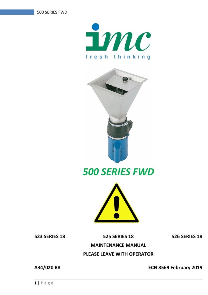
IMC 500 Series User manual

500 SERIES
FOOD WASTE DISPOSERS
MAINTENANCE MANUAL
PLEASE LEAVE WITH OPERATOR
523 SERIES 17 525 SERIES 17 526 SERIES 17
A34/020 R6 ECN 7872 August 2012
IMC Mainland Agent:
The Green Machine Ind.
Tel. +31 ( 0 ) 653192745
info@thegreenmachine.nl
www.thegreenmachine.nl

500 Series Food Waste Disposer
EC DECLARATION OF CONFORMITY
(Guarantee of Production Quality)
We, Imperial Machine Company Limited of:
Unit 1, Abbey Road, Wrexham Industrial Estate, Wrexham, LL13 9RF
Declare under our sole responsibility that the machines:
523 – SERIES 17
525 – SERIES 17
526 – SERIES 17
As described in the attached technical documentation is in conformity with the Machinery
Directive 98/37/EC (formerly 89/392/EEC) and is manufactured under a quality system BS EN
ISO 9001. It is also in conformity with the protection requirements of the Electro Magnetic
Compatibility Directive 2004/108/EC and is manufactured in accordance with harmonised
standards EN61000-6-1:2001 Immunity and EN61000-6-3: 2001 Emissions (plus product specific
standards).
IMC’s product range also satisfy the essential health and safety requirements of the Low Voltage
Directive 2006/95/EC and are manufactured in accordance with standards BS EN 60335-1 and
relevant product specific standards.
Approved by S Witt, Product Support Manager
Signed at Wrexham, Date August 2012

500 Series Food Waste Disposer

500 Series Food Waste Disposer
INDEX
GUARANTEE..................................................................................................1
WASTE OUTLET CONNECTION....................................................................1
WATER SUPPLY CONNECTION ...................................................................2
ELECTRICAL CONNECTION .........................................................................2
RELEASING A JAM........................................................................................3
NOTE...............................................................................................................3
FAULT DIAGNOSIS........................................................................................4
Machine does not start ..............................................................................4
Unexpected system stop...........................................................................4
Waste not processed .................................................................................4
MAINTENANCE ..............................................................................................5
ORDERING SPARE PARTS:..........................................................................5
MATERIAL CONTENT....................................................................................5
WIRING DIAGRAMS.......................................................................................6
Figure 1 - Wiring Diagram, Single Phase..................................................6
Figure 2 - Wiring Diagram, 3 Phase 4 Wire...............................................7
Figure 3 - Wiring Diagram, 3 Phase 5 Wire...............................................7
Figure 3 - Wiring Diagram, 3 Phase 5 Wire...............................................8
BASIC UNIT EXPLODED VIEW......................................................................8
BASIC UNIT EXPLODED VIEW......................................................................9
523 EXPLODED VIEW..................................................................................11
525 EXPLODED VIEW..................................................................................13
526 EXPLODED VIEW..................................................................................15

500 Series Food Waste Disposer 1
GUARANTEE
This machine is guaranteed by IMC for 1 Year from the date of purchase from
IMC or from one of its stockists, dealers or distributors.
The guarantee is limited to the replacement of faulty parts or products and
excludes any consequential loss or expense incurred by purchasers. Defects
which arise from faulty installation, inadequate maintenance, incorrect use,
connection to the wrong electricity supply or fair wear and tear are not
covered by the guarantee.
PLEASE OBSERVE THESE INSTRUCTIONS CAREFULLY
This guarantee applies in this form to installations within the UK only.
WASTE OUTLET CONNECTION
All 500 Series Disposers are fitted with a neoprene housing which is designed
to couple to a 42mm copper or plastic fitting, lead piping should not be used.
The size of the waste outlet must not be reduced. A running trap should be
fitted although ‘P’ or ‘S’ type traps can be used. Do not fit a bottle trap. The
length of run between the machine and the main junction must be kept to a
minimum and the pipe must have a positive fall of at least 1 in 7. Changes of
direction should be made with swept bends rather than elbows, and cleaning
eyes should be fitted where possible, in accordance with standard plumbing
practice.
The waste outlet position can be changed by loosening the hose clip at the
top of the neoprene housing. The motor and housing can then be rotated until
the outlet is in the required position. Tighten the hose clip once the outlet is in
the required position.
All Waste Disposers must have an independent drain pipe that does not also
serve sinks, dishwashers or similar equipment. The end of the waste pipe
must be beyond any grease traps and if the outlet feeds into an outside gully,
the pipe should enter the gully below the covering grid. Use a back entry yard
gully.
When fitting the trap make certain that the top invert of the trap lies below the
rubber outlet spout of the waste disposer. Failure to do this will prevent the
machine from draining completely. Also ensure that on all models the outlet
tail does not enter the outlet spout beyond the register, if this tail is fitted to
deeply into the spout it will obstruct the outlet flow
The 523 Disposer is sink mounted and the neoprene housing contains an inlet
boss for the sink overflow near the top of the housing. If this is required the
center of boss needs to be cutout before the overflow is connected.

2500 Series Food Waste Disposer
WATER SUPPLY CONNECTION
A cold water supply with a minimum head of 4m is required on the 525 and
526 Disposers. This is connected to the units at the solenoid valve using a
15mm compression joint, supplied with the machine. A stopcock should be
fitted to the water supply. The 523 disposer draws its water supply from the
sink tap.
The 500 series machine is to be fed by a cistern tank not mains water supply.
ELECTRICAL CONNECTION
All electrical work must be carried out by a qualified electrician and in
accordance with the IEE Codes of Practice. Examine the rating plate
attached to the motor to ensure that the characteristics shown are correct for
the supply available. The cables fitted to the controller are the minimum
required for individual connection to the mains supply. Site conditions may
vary with additional length of cable run, encapsulation in trunking, bunched
with other cables etc. Should this apply, the electrician must alter the cable
accordingly.
All machines are supplied with a starter with forward, reverse and stop
buttons. Where automatic water control is supplied the starter also controls
the water flow. This unit must be connected to the mains supply using the
starter provided. Omission of the starter eliminates overload protection for the
motor and will invalidate the guarantee.
The 500 Series Disposers should be connected to a 30A isolator providing at
least 3mm separation in all poles. The table below illustrates typical fuse
ratings for an ambient temperature of 25 to 35°C. Should the environment
temperature be greater than this, adjust accordingly.
Voltage Full Load Current Fuse Rating per Phase
230 – 1 – 50 5.0 Amps 13 Amps
115 – 1 – 60 10.0 Amps 13 Amps
220 – 1 – 60 5.6 Amps 13 Amps
254 – 1 – 60 5.2 Amps 13 Amps
400 – 3 – 50 1.7 Amps 5 Amps
220 – 3 – 50 3.0 Amps 5 Amps
230 – 3 - 60 2.7 Amps 5 Amps
440/460 – 3 – 60 1.7 Amps 5 Amps
The supply to the machine must also be protected by a 30mA RCD.
Warning: This appliance must be earthed.
If the supply cord becomes damaged it must be replaced by qualified
electrician in order to avoid a hazard.

500 Series Food Waste Disposer 3
RELEASING A JAM
Food Waste Disposers can jam under overload or if unsuitable materials are
placed inside. IMC machines are designed to withstand this and no damage
will normally result as the machine will switch itself off. It is necessary to clear
the jam as follows:
1. Switch off at the mains isolating switch.
2. Remove the baffle by unscrewing the interlock knob and lifting off.
3. Take out any bulk waste in the disposal chamber. Rubber gloves are
recommended
4. If the item which blocked the disposer is apparent, remove it.
5. A release wrench is provided with which to turn the rotor if it is jammed.
Place the hexagon socket of the wrench over the hexagonal boss on
the centre of the rotor and lever backwards and forwards until the
jammed material releases. Remove the release wrench and pull out
the material.
6. Replace the wrench, engaging the hexagon and ensure that the rotor is
totally free throughout its full rotation.
7. Remove the release wrench
8. Replace the baffle, screwing the interlock knob fully home.
9. Switch on at the mains isolating switch.
10. Press the START button and continue disposal.
NOTE
Single phase motors have a thermal overload switch built into the motor. If a
jam occurs and the motor cuts out then a cool down period of approximately
40 minutes will be required before the unit will restart. The thermal overload
will reset itself during this period. Do not try and restart the FWD before the 40
minute time period is over and the motor has cooled down. Doing so could
cause unnessasary damage to the motor.

4500 Series Food Waste Disposer
FAULT DIAGNOSIS
Machine does not start
Cause Action
Electrical supply is not turned on. Switch on supply.
The fuses have blown or the circuit
breaker has tripped. Call site electrician to change fuse or
reset circuit breaker. If problem persists
contact service personnel.
Baffle is not correctly fitted. Check baffle is secured. If problem
persists contact service personnel.
Unexpected system stop
Cause Action
Electrical supply turned off. Switch on supply.
The fuses have blown or the circuit
breaker has tripped. Call site electrician to change fuse or
reset circuit breaker. If problem persists
contact service personnel.
Baffle is not correctly fitted. Check baffle is secured. If problem
persists contact service personnel.
Waste jammed in disposer grinding
unit. Remove blockage from grinding unit.
See instructions on page 3.
Motor overload has tripped. Allow motor to cool for 10 minutes and
restart. If problem persists contact
service personnel.
Waste not processed
Cause Action
A blockage has occured in the waste
pipe. Clear blockage from waste pipe

500 Series Food Waste Disposer 5
MAINTENANCE
12 Monthly, All models
Check for bearing wear by the sound of motor and side to side movement of
rotor.
WARNING – BEFORE ATTEMPTING SERVICE WORK ENSURE THAT
ELECTRICITY AND WATER SUPPLIES ARE TURNED OFF AT THE MAIN
SUPPLY AND STOP COCK
ORDERING SPARE PARTS:
In the event that spare parts or accessories need to be ordered, please
always quote the SERIES AND SERIAL NUMBER of the machine. This is to
be found on the rating plate located near the supply cable.
For installations outside the UK please contact your supplier.
For information on IMC spares and service support (if applicable), please call
IMC on +44 (0)1978 661155. Alternatively, contact us via email or fax:
IMC Service Desk Fax: +44 (0)1978 667766
E-mail: service@imco.co.uk
IMC Spares Desk Fax: +44 (0)1978 667759
E-mail: spares@imco.co.uk
MATERIAL CONTENT
The 500 Series disposers contain the following material:
Metals Stainless steel, mild steel, brass and copper.
Plastics and rubber Neoprene rubber. ABS and nylon
Other Electrical components

6500 Series Food Waste Disposer
WIRING DIAGRAMS
Figure 1 - Wiring Diagram, Single Phase
For supply: 230 –1 – 50, 115 – 1 – 60, 220 – 1 – 60 & 254 – 1 – 60

500 Series Food Waste Disposer 7
Figure 2 - Wiring Diagram, 3 Phase 4 Wire
For supply: 400 – 3 – 50, 220 – 3 – 50, 440/460 – 3 – 60 & 230 – 3 – 60.

8500 Series Food Waste Disposer
Figure 3 - Wiring Diagram, 3 Phase 5 Wire
For supply: 400 – 3 – 50.

500 Series Food Waste Disposer 9
BASIC UNIT EXPLODED VIEW
518
817
10
2019
6
15
1
14
7
4
3
12
13
2
NOTEORIENTATION
OFLIPSEALS
**SINGLE PHASE
MOTOR SHOWN

10 500 Series Food Waste Disposer
Item
number Part number Description
1 A02/050 BROWN LIP SEAL
2 A02/051 BLACK LIP SEAL
3 A02/054 SPEEDI SLEEVE
4 A028/704 WARNING LABEL
5 C14/014-M1 CUTTER
6 C14/023-M1 ROTOR
7 D14/012 KEY
8 D19/039 M6X16L HEX SCREW
9 - -
10 D25/020 WASHER
11 - -
12 D26/010 TENSION PIN
13 G40/238 MOTOR 1ph
G40/223 MOTOR 3ph
14 L52/001 DISTANCE RING
15 E35/076 SEAL PROTECTOR
17 K09/029 LOCTITE 270
18 K09/079 ARALDITE
19 K09/115 HYLOMAR 303 SILICONE
20 D25/085 WASHER
When ordering spare parts or accessories always quote the SERIES
NUMBER of the machine, found on the rating label.

500 Series Food Waste Disposer 11
523 EXPLODED VIEW
7
8
5
6
12
3
12
4
14 9
13
1
15
10
3
10
11

12 500 Series Food Waste Disposer
When ordering spare parts or accessories always quote the SERIES
NUMBER of the machine, found on the rating label.
PartsList DESCRIPTIONQTY
PARTNUMBERITEM RATINGLABEL11 CABLEGLAND
1
A10/280
2SINKOUTLETGASKETANGLED1A11/0273 RUBBERHOUSING1E07/018A4 SINKOUTLET
1
E10/016
5CLAMP3E10/0176 SINKSTOPPER1E10/0187 SILVERSAVER1E10/0198 5001PHCONTROLBOX1G30/3609
1PHMOTORCABLE1G60/49110
1PHMAINSCABLE1G60/49311
HOSECLIP80-100mmDIA
2J06/00612 HOSECLIP40-60mmDIA1J06/01013 HOSECLIP150-180mmDIA1J06/01414 BASICUNITASSY5001PH1S52/010
15 BASICUNITASSY5003PH1S52/020
5003PHCONTROLBOX
1
G30/293
3PHMOTORCABLE
1
G60/165
3PHMAINSCABLE1G60/154

500 Series Food Waste Disposer 13
525 EXPLODED VIEW
22
9
4
21
5
6
14 19
8
17
7 18
16
20 2
15
13
11 12
1

14 500 Series Food Waste Disposer
When ordering spare parts or accessories always quote the SERIES
NUMBER of the machine, found on the rating label.
Parts List DESCRIPTIONQTY
PART NUMBERITEM RATING LABEL1A08/4801 CABLE GLAND NUT3A10/2242 CABLE GLAND M20 BLACK3A10/2803 GASKET1A11/1764 SCREW M4 X 12L SS PAN
4
D21/038
5WASHER M4 SHAKEPROOF SS4D25/0076 RUBBER TOP HOUSING1E07/020
7HOPPER ASSEMBLY-500 FWD1E35/0458 CONTROL BOX ASSEMBLY 500 1 PH1G30/3609 INTERLOCK CABLE1G60/15210 MOTOR CABLE1G60/49111 MAINS CABLE
1
G60/493
12 BALL VALVE1J03/09313 SOLENOID VALVE1J03/14414 HOSE CLIP 40-60mm DIA1J06/01015 HOSE CLIP 150-180mm DIA1J06/01416 HOSE CLIP
1
J06/039
17 SILICONE OILA/RK07/06318 LOCTITE 542A/RK09/02719 BASIC UNIT ASSY 500 1PH1S52/01020 ELECTRICS PLT ASSY 500 FWD1S52/02521 BAFFLE ASSEMBLY FWD 500
1
S52/031
22

500 Series Food Waste Disposer 15
526 EXPLODED VIEW
ONLY ADDITIONAL PARTS TO THE 525 ASSEMBLY ARE SHOWN
11
10
6
9
19
14 15
13
78
1
3
4
5
3 3
12
20
22
23
21
24

16 500 Series Food Waste Disposer
When ordering spare parts or accessories always quote the SERIES
NUMBER of the machine, found on the rating label.
Parts List DESCRIPTIONQTY
PART NUMBERITEM BLIND GROMMET PV626
4
A10/134
1CABLE GLAND3A10/2802 INSERT PLAIN 25x16G SQ TUBE3A13-0643 ADJUSTABLE FOOT M8x401A13/0564 INSERT M8 THREAD 25x16G SQ TUBE1A13/065
5SCREW M4 X 12L SS PAN
6
D21/038
6SCREW M6x12 PAN SS2D21/0507 WASHER M6 SHAKEPROOF SS2D25/0058 WASHER M4 SHAKEPROOF SS6D25/0339 OPTIONAL SIDE PANEL FWD 5261E3/05610 TOP SURROUND AND HOPPER-500 FWD
1
E35/050
11 FRAME ASSEMBLY FWD526
1
E35/051
12 FRONT PANEL 5262E35/06213 BRACKET2E60/00614 BACK PLATE1E60/00715 SEE 525 EXPLODED VIEW ABOVE119 GROMMET
2A10-01220 SCREW M5 X 12 SS PAN2D21/04421 WASHER M5 TYPE A SS2D25/02122 WASHER M5 SHAKEPROOF SS2D25/00423 WATER INLET WASHER3A11/17724
CONTROL BOX
Other manuals for 500 Series
2
This manual suits for next models
3
Table of contents
Other IMC Garbage Disposal manuals
Popular Garbage Disposal manuals by other brands

Jatco
Jatco J-5000 SM-P 200 ABV Installation instruction

Frymaster
Frymaster BKSDU Installation & operation manual

Ninestars
Ninestars DZT-70-11 user manual

KWC
KWC RODAN RODX605SL Installation and operating instructions

Husqvarna
Husqvarna LX 95 Operator's manual

Stark
Stark 61021 Owner's manual and safety instructions