IMC 700 Series Owner's manual

700 SERIES FOOD WASTE DISPOSERS
Installation, Operating and Servicing
Instructions
A34/006 R7 ECN 4825 February 2021
Please make a note of your product details for
future use:
Date Purchased:_________________________
Model Number:__________________________
Serial Number:__________________________
Dealer:_________________________________
________________________________
_______

CONTENTS
CONTENTS...........................................................................................................2
IMPORTANT INFORMATION ...............................................................................3
DELIVERY.............................................................................................................4
INTRODUCTION ...................................................................................................4
INSTALLATION.....................................................................................................4
PROCEDURE........................................................................................................4
Waste Outlet Connection ....................................................................................5
WATER SUPPLY ..................................................................................................6
ELECTRICITY SUPPLY CONNECTION...............................................................6
COMMISSIONING.................................................................................................7
USAGE..................................................................................................................7
OPERATION..........................................................................................................8
RELEASING A JAM..............................................................................................9
WATER FLOW CONTROL (OPTIONAL EXTRA)...............................................10
CLEANING..........................................................................................................11
MAINTENANCE ..................................................................................................11
DO’S AND DON’TS.............................................................................................11
FAULT DIAGNOSIS............................................................................................12
Machine does not start..................................................................................12
Unexpected system stop...............................................................................12
Waste not processed.....................................................................................12
GUARANTEE......................................................................................................13
SERVICE INFORMATION...................................................................................14

IMPORTANT INFORMATION
Read these instructions carefully before using this product, paying
particular attention to all sections that carry warning symbols, caution
symbols and notices. Ensure that these are understood at all times.
WARNING!
This symbol is used whenever there is a risk of personal injury.
CAUTION!
This symbol is used whenever there is a risk of damaging your Lincat
product.
NOTE:
This symbol is used to provide additional information, hints and tips.
KEEP THIS MANUAL FOR FUTURE REFERENCE
WARNINGS AND PRECAUTIONS
This appliance must be installed, commissioned and serviced by a qualified
person in accordance with national and local regulations in force in the
country of installation.
If the supply cord is damaged, it must be replaced by the manufacturer, its
service agent or similarly qualified person.
Ensure that the plug/socket is accessible at all times.
Strip plastic coating and clean the appliance before use.
Disconnect this appliance before servicing, maintenance or cleaning.

The packaged machine also comes with a Release Key and Wall Plaque.
Please notify the carrier and the supplier within 24 hours if anything is missing or
damaged.
Check that the correct machine has been supplied and that the voltage, marked
on the rating plate on the motor, is suitable for the supply and control voltage
available.
These machines are intended for the disposal of food waste matter by maceration
under water flow and discharge into the drainage system. Before fitting this
appliance ensure that the installation is allowed by the authorities.
For the installer:
These instructions contain important information designed to help the user obtain
the maximum benefit from the investment in an IMC food waste disposer. Please
read them carefully before starting work, and consult the supplier in the event of
any queries. Be sure to leave this Instruction Manual with the user after
installation of the machine is complete.
The 723 is designed to be welded into a sink outlet. Weld the disposer inlet
assembly into a 83mm diameter prepared hole in the base of the sink and the
water inlet into a 22mm diameter prepared hole in the side of the sink.
The 725 is designed to be welded into a tabletop, the required size of the cutout in
the tabletop is shown on the next page.
The 726 Dump Station is designed to be free standing and must be bolted to the
floor, using the bolt holes provided, to avoid straining the service connections.
When installing the food waste disposer ensure that the controls are located in a
position that is readily accessible to unit operator.
The wall plaque supplied with the machine should be placed in a prominent
position near the machine.
DELIVERY
INTRODUCTION
INSTALLATION
Procedure

Figure 2 –725 Tabletop cutout details
Waste Outlet Connection
All 700 Series Disposers have a 2” BSP female threaded outlet which is designed
to be connected to 54mm copper or plastic piping. The size of the waste outlet
must not be reduced. A running trap should be fitted although ‘P’ or ‘S’ type traps
can be used. Do not fit a bottle trap. The length of run between the machine and
the main junction must be kept to a minimum and the pipe must have a positive
fall of at least 1 in 7. Changes of direction should be made with swept bends
rather than elbows, and cleaning eyes should be fitted where possible, in
accordance with standard plumbing practice.
The waste outlet position can be rotated at 90° intervals by unbolting the waste
outlet casting from the hopper flange plate. Rotate the motor and waste outlet
casting to the required orientation. Check that the gasket between the waste
outlet casting and the flange plate is in place. Refit the nuts and bolts and tighten
uniformly all round. Do not over tighten, but ensure that the gasket is nipped firmly
and the hopper is rigidly fixed without any distortion of its bottom flange.
All Waste Disposers must have an independent drain pipe that does not also
serve sinks, dishwashers or similar equipment. The end of the waste pipe must be
beyond any grease traps and if the outlet feeds into an outside gully, the pipe
should enter the gully below the covering grid. Use a back entry yard gully.
When fitting the trap make certain that the top invert of the trap lies below the
waste outlet of the waste disposer. Failure to do this will prevent the machine from
draining completely. In case of difficulty contact your supplier or Lincat.

A cold water supply with a minimum head of 0.2 to 10 bar is required. This is
connected to the units at the water control valve using a 15mm compression joint,
supplied with the machine. A stopcock should be fitted to the water supply.
The rate of water flow for the disposal of normal food waste is 14-18 litres per
minute for 700 Series machines. Adjust the water supply control valve to achieve
the desired flow rate.
These machines have approval from the Water Research Centre to be connected
to a potable water supply via a Class A air break or for connection to a storage
cistern by a distributing pipe to which no fittings for other purposes are connected.
Lincat can supply Class A air break parts if required.
All electrical work must be carried out by a qualified electrician and in accordance
with the IET Codes of Practice. Examine the rating plate attached to the motor to
ensure that the characteristics shown are correct for the supply available. The
cables fitted to the controller are the minimum required for individual connection to
the mains supply. Site conditions may vary with additional length of cable run,
encapsulation in trunking, bunched with other cables etc. Should this apply, the
electrician must alter the cable accordingly.
All machines are supplied with a starter with forward, reverse and stop buttons.
The starter also controls the water flow. This unit must be connected to the mains
supply using the starter provided. Omission of the starter eliminates overload
protection for the motor and will invalidate the guarantee.
The 700 Series Disposers should be connected to a 30A isolator providing at least
3mm separation in all poles. The table below illustrates typical fuse ratings for an
ambient temperature of 25°C to 35°C. Should the environment temperature be
greater than this, de-rate accordingly.
Unit
Voltage
Full Load Current
Fuse Rating per
Phase
700
400-3-50
2.8 Amps
5 Amps
230-1-50
7.4 Amps
15 Amps
Warning: This appliance must be earthed.
If the supply cord becomes damaged it must be replaced by qualified electrician in
order to avoid a hazard.
WATER SUPPLY
ELECTRICITY SUPPLY CONNECTION
1. Turn on the water supply, and check for leaks in the supply pipework.
2. Switch on the electricity supply.
3. Press one of the start buttons the unit will start and water flow into the
disposer. Press the red button to stop the machine. All models are
reversing and have two start buttons, one for each direction (check them
both).
4. Inspect the waste piping for leaks. Adjust the water supply control valve to
achieve the desired flow rate. Maximum flow is with the handle in line with
the pipe.
5. Feed a small amount of food into the disposer to check that there are no
obstructions in the waste pipe.
6. With the machine running unscrew the hopper baffle knob. The machine
will switch itself off. By the time the knob of fully unscrewed and the baffle
removed the rotor in the grinding chamber will have stopped.
USAGE
The 700 series disposers are designed for the disposal of food waste. Fat can be
safely disposed of provided that it has solidified. Non-food waste may also be
disposed of in small quantities providing they are mixed in with the food waste.
Do not introduce waste into the machine unless it is running. More efficient
disposal will be obtained by introducing mixed rather than accumulating and
introducing waste of a similar nature into the disposer.
COMMISSIONING
DO NOT PUT CLING FILM, LIQUID FAT, STRING, CLOTH, PLASTIC,
WIRE, GLASS, CORK, STYROFOAM OR METAL OBJECTS INTO
THE DISPOSER.

723 Disposer
1. Turn on the cold water tap to medium flow.
2. Press the START button. NOTE units are reversing and have two start
buttons, one for each direction, use them alternately.
3. Feed in the food waste and leave the machine running until the noise of
grinding ceases.
4. Allow to run for 20-30 seconds longer to ensure thorough flushing through.
5. Press the red STOP button and turn off tap.
725 and 726 Series Disposers
1. Close the baffle and screw the interlock knob fully down.
2. Switch on at the mains isolating switch.
3. Press the START button. NOTE units are reversing and have two start
buttons, one for each direction, use them alternately.
4. Place waste food into the baffle and push into the disposal chamber.
5. Allow the machine to run until the disposal is complete. The noise of
operation will indicate when the disposal chamber is empty.
6. Press the red STOP button.
OPERATION

RELEASING A JAM
Food Waste Disposers can jam under overload or if unsuitable materials are
placed inside. IMC machines are designed to withstand this and no damage will
normally result as the machine will switch itself off. It is necessary to clear the jam
as follows: 723 DISPOSER
1. Switch off at the mains isolating switch.
2. Take out any bulk waste in the baffle chamber. Rubber gloves are
recommended.
3. Lower the release wrench though the aperture in the baffles and locate
between the hexagonal boss on the centre of the rotor and the vane of the
rotor. Exert pressure in both directions until the jammed material releases.
4. Remove the release wrench.
5. Switch on at the mains isolating switch.
6. Press the START button and continue disposal.
725 and 726 Series Disposers
1. Switch off at the mains isolating switch.
2. Remove the baffle by unscrewing the interlock knob and lifting off.
3. Take out any bulk waste in the disposal chamber. Rubber gloves are
recommended. If the item which blocked the disposer is apparent, remove it.
4. Place the hexagon socket of the release wrench over the central hexagonal
boss on the rotor and lever backwards and forwards until the jammed
material releases. Remove the release wrench and pull out the material.
5. Replace the wrench and ensure that the rotor is totally free throughout its full
rotation. Remove the release wrench.
6. Replace the baffle, screwing the interlock knob fully home.
7. Switch on at the mains isolating switch.
8. Press the START button and continue disposal.
In the event of difficulty call your supplier or the manufacturer for a qualified
service engineer.

WATER FLOW CONTROL (OPTIONAL EXTRA)
Your IMC Food Waste Disposer is equipped with a device with which the operator
can adjust the volume of water that flows through the Food Waste Disposer whilst
it is processing food waste.
To reduce water flow, simply turn the water control knob to the left i.e. anti-
clockwise.
To increase water flow, turn the knob to the right i.e. clockwise.
When operating the FWD, the water flow control should initially be set at its
highest position before turning it down whilst the waste is being processed. The
rate of water flow can be adjusted up or down for each installation to take account
of unique factors such as the length of, and number of bends in, the drainage
piping, the fall of the pipe, the amount of liquid already present in the waste and
whether a Dewaterer and / or Grease Trap is fitted downstream of the FWD.
When operating the system on reduced water flow it is recommended that, at the
end of each “session,” the water flow is turned up full for a minimum of 15
seconds to ensure that any residue is flushed through the drainage system. A
bucket of warm, soapy water poured into the FWD’s hopper at the end of each
day will both clean the equipment and help disperse any residual solids in the
piping.
Note: The control knob operates within an arc from vertical (min water flow) to the
3 o’clock position (max water flow). Please do NOT force the control knob beyond
its end stop positions.
Unless the FWD is being used to process food that is either consistently very wet
or very dry, Lincat recommends that the water pressure should be set at the mid-
point of the published scale when the equipment is first installed.

723 Disposers
Clean the sink thoroughly after use.
725 and 726 Series Disposers
Clean down thoroughly after use especially inside the hopper. Unscrew the
interlock knob and open the baffle to gain access internally.
Cleaning is assisted by the use of a low pressure spray, an IMC Pre-Rinse Spray
or a Reel-Kleen retractable hose reel.
Wipe over the exterior of the machine, including the back areas not normally
visible with a damp cloth, using a mild detergent if required.
DO NOT USE CLEANING MATERIALS CONTAINING ABRASIVES OR
BLEACHES. DO NOT STEAM CLEAN.
12 Monthly, All models
Check for bearing wear by the sound of motor and side to side movement of rotor.
Remove and clean the water strainer incorporated in the water control valve.
WARNING –BEFORE ATTEMPTING SERVICE WORK ENSURE THAT
ELECTRICITY AND WATER SUPPLIES ARE TURNED OFF AT THE MAIN
SUPPLY AND STOP COCK.
Regular inspection of catering equipment can extend its working life. Please
phone Lincat for details of service contracts.
DO’S AND DON’TS
DO Ensure controls and isolator are accessible to the disposer operator.
DO Switch on disposer before introducing the waste.
DO Clean the machine after use.
DON’TPlace hands inside the grinding chamber.
DON’T Put cling film, liquid fat, string, cloth, plastic, wire, glass, cork,
styrofoam or metal objects into the disposer.
CLEANING
MAINTENANCE
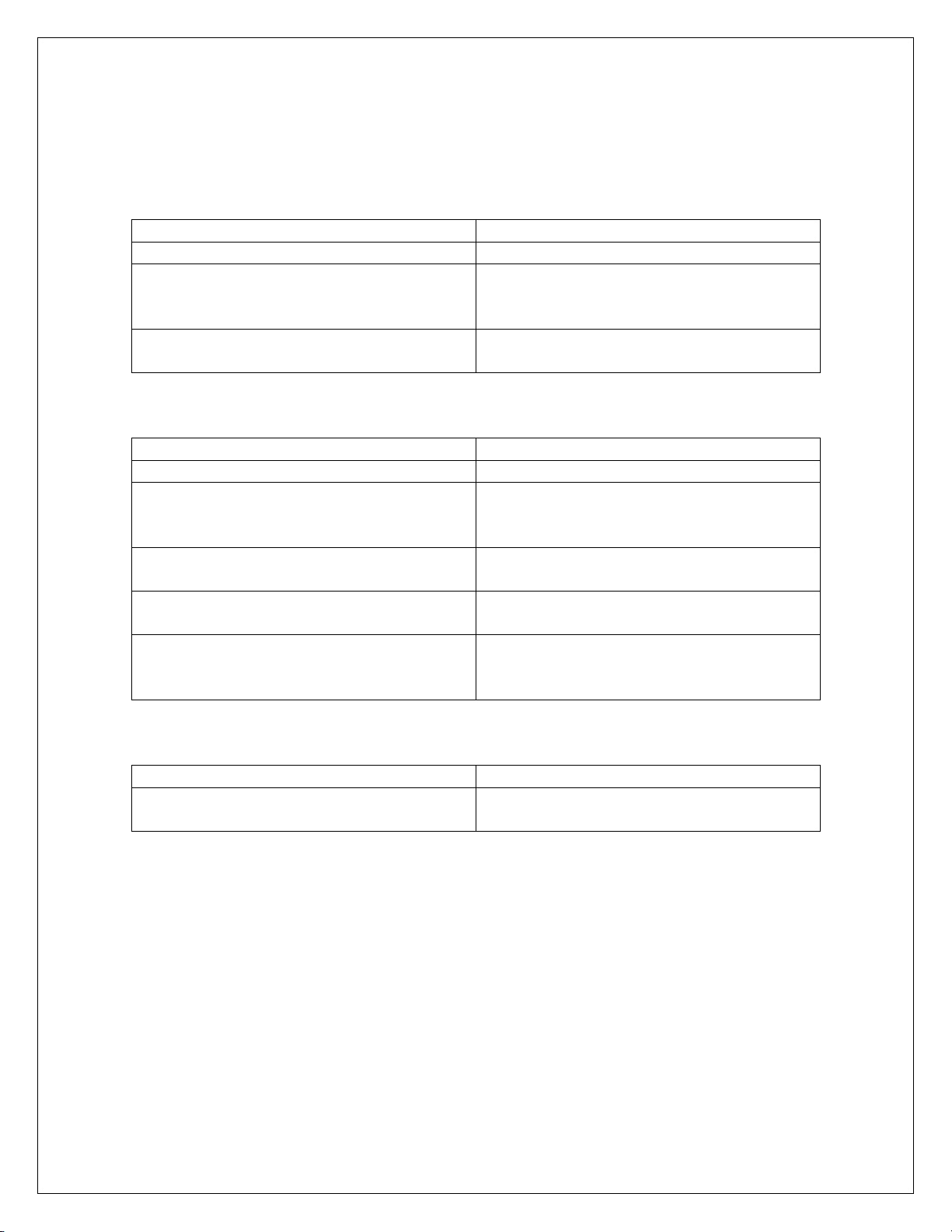
FAULT DIAGNOSIS
Machine does not start
Cause
Action
Electrical supply is not turned on.
Switch on supply.
The fuses have blown or the circuit
breaker has tripped.
Call site electrician to change fuse or
reset circuit breaker. If problem persists
contact service personnel.
Baffle is not correctly fitted.
Check baffle is secured. If problem
persists contact service personnel.
Unexpected system stop
Cause
Action
Electrical supply turned off.
Switch on supply.
The fuses have blown or the circuit
breaker has tripped.
Call site electrician to change fuse or
reset circuit breaker. If problem persists
contact service personnel.
Baffle is not correctly fitted.
Check baffle is secured. If problem
persists contact service personnel.
Waste jammed in disposer grinding
unit.
Remove blockage from grinding unit.
Motor overload has tripped.
Allow motor to cool for 10 minutes and
restart. If problem persists contact
service personnel.
Waste not processed
Cause
Action
A blockage has occurred in the waste
pipe.
Clear blockage from waste pipe

This unit carries a comprehensive UK mainland 2 year warranty. The
guarantee is in addition to, and does not diminish your statutory or legal
rights.
The guarantee does not cover:
Accidental damage, misuse or use not in accordance with the
manufacturer’s instructions.
Consumable items (such as filters, glass, bulbs, slot toaster elements and
door seals.)
Damage due to incorrect installation, modification, unauthorised service
work or damage due to scale, food debris build-up, etc.
The manufacturer disclaims any liability for incidental, or consequential
damages.
Attendance is based on reasonable access to the appliance to allow the
authorised technician to carry out the warranty work.
Service calls to equipment under warranty will be carried out in accordance
with the conditions of sale. Unless otherwise specified, a maximum of 15
minutes of administrative time, not spent directly carrying out servicing work,
is provided for within the warranty. Any requirement for staff attending the
call to spend greater time than 15 minutes due to administrative
requirements, such as on health and safety risk assessments, will be
chargeable at the prevailing rate.
GUARANTEE

For help with the installation, maintenance and use of your Lincat
equipment, please contact our service department:
UK: 01522 875520
For non-UK customers, please contact your local Lincat dealer
All service work, other than routine cleaning should be carried out by one of
our authorised service agents. We cannot accept responsibility for work
carried out by other persons.
To ensure your service enquiry is handled as efficiently as possible, please
tell us:
Brief details of the problem
Product code
All available on serial plate
Type number
Serial number
Lincat reserve the right to carry out any work under warranty, given
reasonable access to the appliance, during normal working hours, Monday
to Friday, 08:30 to 17:00.
SERVICE INFORMATION
This manual suits for next models
3
Table of contents
Other IMC Garbage Disposal manuals


Popular Garbage Disposal manuals by other brands

Leafield Environmental
Leafield Environmental Envirobank 140 Installation guidelines

KitchenAid
KitchenAid KCDB250G2 parts list

BIOLAN
BIOLAN COMPOSTER 550 Instructions for installation, use and maintenance

Jenn-Air
Jenn-Air TC607 Use & care guide

Weber mt
Weber mt CR 8 Operating and maintenance manual

Whirlpool
Whirlpool GC2000PE2 parts manual


