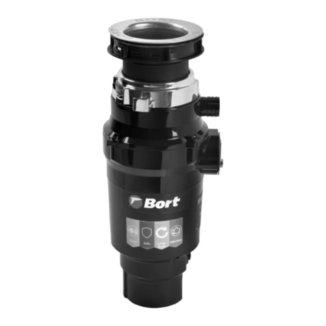
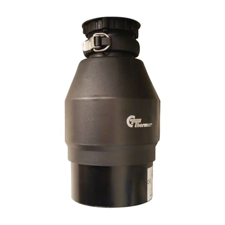
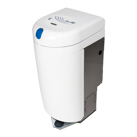
Bort MASTER ECO User manual

MASTER ECO
91275752
TITAN 4000 Plus
91275776
TITAN 5000
91275783
TITAN MAX Power
91275790
TITAN 4000
91275769
DE. Hausmüll zerkleinerer . . . . . . . . . 5
EN. Waste disposer . . . . . . . . . . . . . . . .9
FR. Déchiqueteuse de déchets . . . .12
RU. Измельчитель отходов . . . . . . 16

2
1 2 3 4 5
MASTER ECO 346 мм 180 мм 69 мм 156 мм 127 мм
TITAN 4000 357 мм 170 мм 79 мм 160 мм 127 мм
TITAN 4000
Plus 357 мм 170 мм 79 мм 160 мм 127 мм
TITAN 5000 336 мм 149 мм 69 мм 211 мм 127 мм
TITAN MAX
Power 336 мм 149 мм 69 мм 211 мм 127 мм

3

4

5
INSTALLATIONSANLEITUNG,
INSTANDHALTUNG
UND VERWENDUNG DES ENTSORGERS
Bevor Sie das Produkt installieren, lesen Sie alles sorgfältig
durch. Installations-, Wartungs- und Bedienungsanleitung.
Vor Beginn der Arbeit Bestimmen Sie, welche Werkzeuge,
Materialien und Ausrüstung, die Sie brauchen.
Bevor Sie den Entsorger installieren, stellen Sie sicher, dass
Sie alle erforderlichen Teile des Produkts haben.
Benötigte Werkzeuge und Materialien:
Schraubendreher, Scharnierzange, Isolierband, Schutzbril-
le
ERFORDERLICHE INSTRUMENTE, MATERIALIEN UND
OPTIONALE AUSRÜSTUNG:
ein Kreuzschlitzschraubendreher, ein Entwässerungsboh-
rer, elektrische Klemme 9,5 mm, Gewindemuttern (2),
Siphon 38 mm, Bohrer 33 mm, Hammer, Eisensäge, Was-
serschlauchklemme, Rohrzange, Kupfer Erdungskabel,
Geschirrspüler Abussrohr Kit, elektrisch Schalter, Verlän-
gerungsrohr
1. BESCHREIBUNG DES PRODUKTS ABB.1.1)
Montageeinheit
1. Stopper
2. Waschansch
3. Gummidichtungen (2)
4. Stützring
5. Montagering
6. Schrauben
7. Sicherungsring
8. Schalldämpfender Bildschirm Entsorger
9. Einbaudichtung / Schutzreektor
10. Ösen
11. Unterer Befestigungsring
12. Den Geschirrspüler entleeren
13. Auslassönung Entwässerungssystem
14. Befestigungsschrauben
15. Gummidichtung
16. Flansch
17. Abussrohr mit einem Knie
2. TRENNUNG DES TROPFENHORNS BEACHTUNG!
Zum Zeitpunkt der Installation des Geräts wird empfohlen
Schutzbrille tragen.
Lösen Sie die Mutter (1) an der Oberseite derWasserfalle (4)
mit einem Rohrschlüssel (Abb. 3.1).
relative Luftfeuchtigkeit nicht mehr als 80%.
Lösen Sie die Mutter (2) auf der Oberseite des Verlänge-
rungsrohrs. Entfernen Sie das Verlängerungsrohr.
Lösen Sie die Mutter (3) an der Unterseite des Waschan-
sches.
Schieben Sie den Waschansch nach oben durch
Ablauoch der Spüle und entfernen Sie es (Abb. 3.2).
REINIGEN SIE DEN WASCHFAN-VERPACKUNGSORT
Aus dem Dichtsto oder dem Müll.
HINWEIS: Es kann notwendig sein, die Ablaufbohrung für
zu erweitern
Befestigungsvorrichtung für Befestigungsansche.
Ausrüstung für die Erweiterung der Entwässerungsboh-
rung wird separat erworben.
3. DEMONTAGE DER MONTAGEEINHEIT
Drehen Sie die Baugruppe (Abb.4.1) und lockere die drei
Befestigungsschrauben (1) Der Zugang zum Ring (2).
Trennen Sie den Sicherungsring vom Flansch mit einem
Schraubenzieher. Jetzt kann die Montageeinheit demon-
tiert werden.
4. BEFESTIGEN SIE DIE BEFESTIGUNGSMONTAGE WA
SCHEN ABB.5.1.
1. Eine oder zwei Gummidichtungen (2) unter dem Wasch-
ansch (1) anbringen. Stelle sicher das Die Entwässerungs-
önung ist nicht verstopft und auf eingestellt Flansch-
scheibe / Dichtung. um zu Der Flansch der Spüle wurde
an Ort und Stelle, Sie müssen es mit einer schweren Last
zerquetschen.
(Um Kratzer zu vermeiden, verwenden Sie ein Handtuch
als Futter.)
2. Legen Sie den zweiten Gummiteil auf den Boden der
Spüle eine Dichtung (2), eine Kartondichtung (optional)
(3) und einen Metallstützring (4) (ache Seite nach oben).
3. Während Sie die zweite Gummidichtung halten, Karton-
polsterung (optional) und einen Metallstützring, legen Sie
den Befestigungsring (5) auf den Flansch der Spüle, so dass
es mit dem Stützring ausgerichtet.
4. Drücken Sie fest auf den Boden der Spüle Gummi Dich-
tung, Pappdichtung, Unterstützung Ring und Montagering
schieben Sie den Sprengring (7) auf den Flansch der Spüle
es rastet in die Flanschnut ein.
5. Ziehen Sie die drei Befestigungsschrauben (6) an Die Be-
festigungsanordnung war dicht und gleichmäßig drückte
auf die Spüle.
5. REINIGUNG DER ABLAUFROHRE
Wenn Sie das Abussrohr nicht reinigen, kann es verstop-
fen.
1. Entfernen Sie den Wasserabscheider. (Abb.6.1)
2. Entfernen Sie mit einem Reiniger alle Feststoe Nie-
derschlag im horizontalen Teil der Entwässerung Rohre,
Deutsch

6
bewegt sich mit Seite des Siphons in Richtung der Haupt-
leitung Rohr.
WENN DER GESCHIRRSPÜLER NICHT SEIN WIRD
AN DEN ENTSORGER VERBUNDEN, GEHEN SIE ZU TEIL 7
DIESER ANLEITUNG
6. ANSCHLUSS DES GESCHIRRSPÜLERS
MASCHINEN UND TRANSFERANSCHLUSS
Das Abwasser kann durch den Einlass in seinem Oberteil in
den Entsorger abgegeben werden Teile.
Bei allen Modellen im Saugrohr gibt es Partition. Die Parti-
tion muss entfernt werden.
HINWEIS: Wenn der Geschirrspüler wird installiert, ohne die
Partition zu entfernen, Geschirrspülen kann überschwem-
men.
PLATTE / PARTITION ENTFERNEN
1. Legen Sie den Entsorger auf eine Seite und legen Sie ihn
Schraubenzieher in den Anschluss für den Geschirrspüler,
schieben Sie es bis es wird nicht an der Trennwand am En-
de des Abzweigrohrs anliegen.
2. Mit mehreren Hammerschlägen das Septum im Ab-
zweigrohr ausbrechen (Abb.7.1).
3. Entfernen Sie die geprägte Trennwand von der Entsor-
gungsschale.
Wenn die Spüle voll mit Flüssigkeit ist, sollte sie an den Ein-
lass des Überlaufauslasses angeschlossen werden Rohre
(Abb.7.2).
Zum Anschluss an den Überlauf-Einlass entfernen Sie die
Abdeckung des Auspurohrs, indem Sie den Deckel ab-
schrauben (Abb.7.3).
7. ANSCHLUSS DES ENTSORGERS AN DIE
BEFESTIGUNGSEINHEIT
BEACHTUNG!
Um Verletzungen zu vermeiden, folgen Sie den Anweisun-
gen so dass während der Entfernung und Installation eines
Teils Dein Körper war nicht unter dem Entsorger; Während
der Installation ist es möglich, es fallen zu lassen.
Entfernen Sie alle Gegenstände aus der Mahlkammer Pro-
dukt vor der Installation auf der Spüle.
1. Installieren Sie das Produkt so, dass bieten einfachen
Zugri auf die Schaltäche „Neustart“ Motor bendet sich
im unteren Teil des Körpers. Blockiere diesen Ort nicht mit
irgendwelchen Objekten.
2. Platzieren Sie den Entsorger mit drei Halterungen Schlei-
fen (1) in die Gleitposition durch Montageschienen (2).
(Abb.8.1)
3. Heben Sie den Entsorger an, legen Sie den Deckel ein
Ende (Einbaudichtung) in der Halterung und drehen Sie
den Einstellring nach rechts (mit einem Schraubenschlüs-
sel oder einstellbar Zange), bis die Montageschlaufen (3)
gegenüber den Montageschienen xiert sind (Abb. 8.2).
Stellen Sie sicher, dass alle drei Befestigungsschlaufen ver-
riegelt sind. Disponent ist installiert.
4. Lassen Sie Wasser in die Spüle laufen und prüfen Sie die
Anschlüsse auf Undichtigkeiten.
5. Setzen Sie den geräuschabsorbierenden Bildschirm in
den Abuss ein Loch ache Seite nach oben. (Abb.8.3)
8. ANSCHLUSS DES AUSGANGSROHRES
Zum Abussrohr
BEACHTUNG!
Es wird empfohlen, eine Schutzbrille zu tragen, wenn Sie
den Entsorger installieren.
Bei allen Modellen ist das Abussrohr angeschlossen mit
einer Schraubverbindung (Abb.9.2).
Verwenden Sie nur ein Sanitärdichtmittel zum Verbinden
des Flansches der Spüle mit dem Entsorger.
Verwenden Sie keine Dichtstoe für Rohrgewindeverbin-
dungen oder anaerobe Verschraubungen Dichtstoe.
Sie können das Produkt beschädigen.
Überprüfen Sie den Entsorger und die Armaturen regelmä-
ßig auf Undichtigkeiten, da diese undicht sind Wasser kann
Sachschäden verursachen.
Der Hersteller ist nicht verantwortlich für Sachschäden
durch Wasserlecks.
INSTALLATION DES ABFLUSSSYSTEMS
1. Setzen Sie den Flansch (2) auf das Abussrohr Setzen
Sie die Gummidichtung (1) ein. Befestigen Abussrohr,
ziehen Sie es fest an den Körper Entsorger mit Schrauben
(4). (Abb.9.1)
9. ANSCHLUSS DES ENTSORGERS AN DAS ELEKTRI
SCHE NETZWERK
BEACHTUNG! ELEKTRISCHER SCHOCK STROM
• Um einen Stromschlag zu vermeiden, schalten Sie das
Gerät aus, bevor Sie das Produkt installieren oder warten.
• Wenn Sie nicht genug qualiziert sind, Einen Elektriker ru-
fen, um das Produkt zu verbinden an die Macht.
• Wenn ein dreipoliger Erdungsstecker zum Anschließen
verwendet wird ein Drei-Kontakt Steckdose mit Boden.
• Verändern Sie nicht das Design des mitgelieferten Ste-
ckers Gerät.
• Unsachgemäße Erdung der Ausrüstung kann einen elekt-
rischen Schlag verursachen Strom.
• Alle elektrischen Verbindungen müssen mit den elektri-
schen und Normen.
• Schließen Sie den Boden nicht an das Versorgungsrohr
an Gas.
• Schalten Sie die Verteilung nicht ein Schild, bis Sie die
installiert haben Buchsen mit ordnungsgemäßer Erdung.
• Wenn das Netzkabel beschädigt ist, muss es im Kunden-
dienst ausgetauscht werden.
HINWEIS: Der Zugang zu einer geerdeten Steckdose ist er-
forderlich. Installation aller zusätzlichen Steckdosen müs-
sen von einem qualizierten Elektriker ausgeführt werden
und alle Steckdosen müssen ordnungsgemäß geerdet sein.
ON / OFF das Produkt Pneumatischer Schalter Die Brecher
sind mit einem pneumatischen Schalter und einem Verbin-

7
dungsrohr ausgestattet.
Der pneumatische Schalter ist aktiviert / deaktiviert sen-
ding a pneumatic impulse to the control unit.
INSTALLATION OF AIR SWITCH
1. Drill a hole with a diameter of 33 mm in suitable top or
top the panel of a sink. Some sinks may already have a sui-
table A hole for the opening of which is necessary remove
the cover.
2. Unscrew the nut from the body of the push button, whi-
le holding the stainless steel washer and rubber gasket in
place. Place one end of the PVC tube on the spout on the
body Press the other end to A hole in the table top and a
nut located under the countertop. (Fig.10.2)
3. Place the push button housing in the hole and tighten
the nut underneath countertop (enough arm eort). Do
not use the key to tighten nut. (Fig.10.3)
4. Take the other end of the duct and tightly put it on the
spout of the air switch located on the bottom of the dispo-
ser. (Fig.10.4) Hand tighten the clamping nut.
The disposer installation is complete. Before using the
product, read all of the instructions. operation and safety
contained in paragraph 10 of this manual.
In conclusion, install the plug in the sink in the Closed po-
sition. Fill the sink with water, Remove the plug and check
the connections on the a water leakage.
10. ATTENTION! IMPORTANT INSTRUCTIONS FOR
SAFETY
• If the air switch does not work, remove the plug power
supply from the outlet and check the air duct pneumatic
switch and delivered to the outlet electricity.
• This product is designed for grinding food residues at
home; the ingress of substances other than food into the
disposer may cause injury and / or damage property. To
reduce the risk of Do not use a washer with an installed
disposer not for food purposes (for example, for bathing a
child or washing your head).
• Children should be supervised adults and should not play
with a disposer. To reduce the risk of injury
It is necessary to keep a watchful eye on children use of
the product.
• If the wedging in the disposer is eliminated, turn o the
appliance and disconnect it from the electrical network.
Use a wrench for self-removal of jammed waste according
to description in the section „Elimination of jamming dis-
poser„.
• Use tongs or pliers to remove foreign objects from the
product.
• To reduce the risk of injury from particles that are thrown
out by the disposer, it is prohibited to use grinders without
noise shielding screen (Fig.8.3).
Place the plug in the drain hole, as shown in Fig. 11.2 or
11.4. Do not allow the following items to fall into the di-
sposer:
shells, including oyster, caustic means for cleaning pipes or
similar chemical products, glass, porcelain or plastic, large
(hollow) bones, metal objects (bottle caps, cans, or kitchen
appliances), hot fat or other hot liquids.
• Replace worn noise glossy screen / installation gasket /
protective reector if they are worn and are no longer able
to prevent waste or water.
• Wenn der Entsorger ausgeschaltet ist, verwenden Sie
einen Stopper, um dies zu verhindern Fremdkörper beim
Schleifen Kamera. Stellen Sie sicher, dass die Macht des
Entsorgers ist behindert.
• Bevor Sie den Reset-Knopf drücken, den Stau beseitigen
oder Fremdkörper aus der Zerkleinerungskammer entfer-
nen, stellen Sie sicher, dass Das Essen ist ausgeschaltet.
• Halten Sie Hände und Finger außerhalb der Reichweite
von Entsorgungskammer.
BRANDGEFAHR:
Um die Möglichkeit zu minimieren Nicht in der Nähe von
Feuerlöschern lagern Gegenstände wie Lumpen, Papier
oder Aerosoldosen. Lagern oder benutzen Sie kein Benzin
oder ähnliches brennbare Dampf-Gas-Gemische und Flüs-
sigkeit in der Nähe des Entsorgers.
Folgendes nicht zulassen Kamera-Produkte: Farben, Lö-
sungsmittel, Haushalt Reinigungsmittel und Chemikalien,
Automobilüssigkeiten, Kunststoverpackungen.
HANDBUCH
1. Verwenden Sie den Luftschalter (Abb. 11.1), um den Ent-
sorger zu starten.
2. Senken Sie die Lebensmittelabfälle langsam in die Kam-
mer und installieren Sie das Filtergitter in einer vertikalen
Position (so dass es durchießt Wasser) um Lärm zu redu-
zieren und möglich Werfen von Abfall während des Schlei-
fens (Abb. 11.2).
3. Nachdem der Schleifvorgang abgeschlossen ist, schalten
Sie die Entsorger und lassen Sie das Wasser für mindestens
15 laufen s, um die Abussleitung zu spülen.
SOLLTE
• Speisereste unter Druck mahlen kaltes Wasser nicht weni-
ger als 6 Liter / min.
• Mahlen Sie Feststoe wie kleine Knochen und Fruchtrück-
stände zum Reinigen Hackkammern.
• Grind Zitrusfrüchte, Melonen, Gemüse und Kaeeboh-
nen.
• Lassen Sie das Wasser nach dem Schleifen auslaufen min-
destens 15 Sekunden, um den Abuss zu spülen Pipeline.
• Ziehen Sie das Produkt aus der Steckdose, bevor Sie den
festsitzenden Rotor mit einem Werkzeug entfernen.
• Speichern Sie keine Objekte unter dem Display, um den
Zugri auf die Schaltäche zu gewährleisten Neustart.
UNTERLASSEN SIE
• Verwenden Sie kein heißes Wasser beim Schleifen Reste
8
von Produkten (obwohl heiß Wasser durch das Produkt
zwischen Schleifen).
• Schalten Sie das Wasser oder das Produkt erst aus, wenn
das Schleifen beendet ist. Es ist ein Geräusch von laufen-
dem Motor und Laufen Wasser.
• Mahlen Sie keine großen Mengen Ei Schalen, faserige Ma-
terialien zum Beispiel Mais Schalen, Artischocken, etc., um
ein mögliches Verstopfen des Rohres zu vermeiden.
• Nur Lebensmittel mahlen.
• Verwenden Sie dieses Gerät nicht zum Schleifen von har-
ten Materialien wie Glas und Glas Metall.
• Gießen Sie niemals Fett, Öl oder Fett hinein Shell, da dies
zu Verstopfungen führen wird Entwässerungs- und Abwas-
sersysteme.
• Befüllen Sie die Entsorgungskammer nicht mit einer gro-
ßen Menge an Reinigungsmitteln Gemüse. Schalten Sie
stattdessen zuerst das Wasser ein und Entsorger und sen-
ken Sie es allmählich Reinigung.
REINIGUNG DER ENTSORGUNGSKAMMER
Im Laufe der Zeit können Fett / Nahrungsmittelpartikel
in der Mahlkammer anreichern und schützen Reektor,
der einen unangenehmen Geruch verursacht. Zum Reini-
gungsmahlkammer und Reektor:
1. Schalten Sie das GERÄT aus und trennen Sie es vom
Stromnetz.
2. Durch die Abussönung mit einem Schwamm Zum
Waschen den Boden reinigen Oberächen Schutzreektor
und Innenoberteil Kanten der Hackkammer.
3. Setzen Sie den Stopfen in das Abussloch und füllen Sie
das Waschbecken mit halbem Wasser.
4. Mischen Sie 60 ml Backpulver mit Wasser. Schalten Sie
das Produkt ein und ziehen Sie den Stecker aus der Spüle.
Waschen von Fremdpartikeln.
BESEITIGUNG DES KOLBEN-ENTSORGERS
Wenn während des Betriebs der Entsorger Motor angehal-
ten, möglicherweise verklemmte bewegliche Teile.
Um Jammen zu beseitigen:
1. Schalten Sie den Entsorger aus und schalten Sie das Was-
ser aus.
2. Stecken Sie ein Ende des Schlüssels in das mittlere Loch
an der Unterseite des Produkts, um einen eigenständigen
Stecker zu erhalten Beseitigung von festsitzendem Abfall
(Abb. 11.5). Drehen Sie den Schlüssel vor und zurück bis so
lange wie Er wird keine volle Drehung machen. Mitnahme
Schlüssel.
3. Entfernen Sie fremde Objekte aus dem Hilfe tickt mit
langen Handgrien. Geben zum Motor des Produkts 3 bis
5 Minuten abkühlen lassen und den roten Reset-Knopf an
der Unterseite des Entsorgers drücken (Abb.11.6) (Wenn
der Motor nicht anspringt, überprüfen Sie die Schutzschild
für die Anwesenheit von Leistungsschalter und ausge-
brannt Sicherungen).
BEDIENUNG
Wenn Sie Wartungsarbeiten durchführen müssen oder
reparieren Sie das Produkt, wenden Sie sich an einen au-
torisierten Händler Service Center oder zu Ihrem Händler.
Die Garantie erlischt in folgenden Fällen:
- wenn das Produkt mit Beeinträchtigungen verwendet
wurde Anforderungen dieses Handbuchs
- in Gegenwart von Spuren der Önung des Körpers des
Produkts zur Selbstreparatur
Weitere Informationen zu den Garantiebedingungen n-
den Sie in der Garantie Coupon.

9
INSTALLATION INSTRUCTIONS, MAINTENANCE
AND USING THE DISPOSER
Before installing the product, read everything carefully.
Installation, maintenance and use manual. Before starting
work determine which tools, materials, and equipment you
need.
Before installing the disposer, make sure that you have all
the necessary parts of the product.
REQUIRED TOOLS AND MATERIALS:
screwdriver, Hinged pliers, insulation tape, protective
glasses
REQUIRED INSTRUMENTS, MATERIALS AND OPTIONAL
EQUIPMENT:
a Phillips screwdriver, a drainage drill, electrical terminal
9.5 mm, threaded nuts (2), siphon 38 mm, drill 33 mm,
hammer, hacksaw, water hose clamp, pipe pliers, copper
grounding wire, dishwasher drainage pipe kit, electric
switch, extension pipe
1. DESCRIPTION OF THE PRODUCT FIG.1.1
Assembly unit
1. Stopper
2. Washing ange
3. Rubber gaskets (2)
4. Support ring
5. Mounting ring
6. Screws
7. Locking ring
8. Sound attenuating screen Disposer
9. Installation gasket / protective reector
10. Eyelets
11. Lower mounting ring
12. Drain the dishwasher
13. Outlet opening Drainage system
14. Mounting Screws
15. Rubber gasket
16. Flange
17. Drain pipe with a knee
2. DISCONNECTION OF THE DROP HORN ATTENTION!
At the time of installation of the device is recommended
Wear safety glasses. Loosen the nut (1) on the top of
the water trap (4) with a pipe wrench (Fig. 3.1). relative
humidity not more than 80%. Loosen the nut (2) on the top
of the extension pipe. Remove the extension pipe.
Loosen the nut (3) at the bottom of the washing ange.
Push the washing ange upwards through drain hole of
the sink and remove it (Fig. 3.2).
CLEAN THE WASH FAN WRAPPING PLACE FROM THE
SEALANT OR THE GARBAGE.
NOTE: It may be necessary to expand the drain hole for
installation ange fastening disposer.
Equipment for extending the drainage hole is purchased
separately.
English 3. DISASSEMBLY OF THE ASSEMBLY UNIT
• Turn over the assembly (Fig.4.1) and loosen the three
xing screws (1) The access to the ring (2).
• Disconnect the retaining ring from the ange with a
screwdriver. Now the assembly unit can be disassembled.
4. ATTACHING THE FIXING ASSEMBLY TO WASHING
Fig.5.1.
1. Install one or two rubber gaskets (2) under the washing
ange (1). Make sure that The drainage hole is not clogged,
and set to ange washer / gasket. In order to The ange of
the sink became in place, you need to crush it with a heavy
load. (To avoid scratches, use a towel as a lining.)
2. Put the second rubber part on the bottom of the kitchen
sink a gasket (2), a cardboard gasket (optional) (3) and a
metal support ring (4) (at side up).
3. While holding the second rubber gasket, cardboard
padding (optional) and a metal support ring, put the
mounting ring (5) on the ange of the sink so that it aligned
with the support ring.
4. Pressing tightly to the bottom of the sink rubber gasket,
cardboard gasket, support ring and mounting ring, slide
the snap ring (7) onto the ange of the sink so that it snaps
into the ange groove.
5. Tighten the three xing screws (6) to The xing assembly
was tight and evenly pressed to the sink.
5. CLEANING THE DRAIN PIPE
If you do not clean the drain pipe, it can clog.
1. Remove the water trap. (Fig.6.1)
2. Using a cleaner, remove all solid precipitation in the
horizontal part of the drainage pipes, moving with side of
the siphon towards the main pipe.
IF THE DISHWASHER WILL NOT BE CONNECTED TO THE
DISPOSER, GO TO PART 7 OF THIS INSTRUCTION
6. CONNECTING THE DISHWASHER MACHINES AND
TRANSFER CONNECTION
The waste water can be discharged into the disposer
through the inlet in its upper parts.
On all models inside the intake pipe there is partition. The
partition must be removed.
NOTE: If the dishwasher is installed without removing the
partition, dishwashing can be ooding.
REMOVING THE PLATE / PARTITION
1. Place the disposer on one side and place it screwdriver
into the connection for the dishwasher, pushing it until
it will not rest against the partition in the end of the branch
pipe.
2. With several blows of the hammer, knock out the septum
in the branch pipe (Fig.7.1).
3. Remove the embossed partition from the disposer bowl.
If the sink is full of liquid, then it should be connected to the
inlet of the overow outlet pipes (Fig.7.2).
To connect to the overow inlet, remove the exhaust pipe
cover by unscrewing the cover (Fig.7.3).

10
7. CONNECTING THE DISPOSER TO THE FIXING UNIT
ATTENTION!
To avoid injury, follow the so that during the removal and
installation of a part Your body was not under the disposer;
during the installation it is possible to drop it.
Remove any objects from the grinding chamber product
before installing it on the sink.
1. Install the product in such a way that provide easy access
to the restart button engine located in the lower part of the
body. Do not block this place with any objects.
2. Place the disposer with three mounting loops (1) into the
sliding position by mounting rails (2). (Fig.8.1)
3. Lift the disposer, insert the top end (installation gasket)
in the mounting and turn the setting ring to the right (with
a wrench or adjustable pliers) until the mounting loops are
xed (3) with respect to the mounting rails (Fig. 8.2).
Make sure that all three mounting loops are locked.
Disposer is installed.
4. Run water into the sink, then check the connections for
leaks.
5. Insert the noise absorbing screen into the drain hole at
side up. (Fig.8.3)
8. CONNECTING THE OUTLET PIPE
To the DRAIN PIPE ATTENTION!
• It is recommended to wear protective goggles when
installing the disposer.
• For all models, the drain pipe is connected using a screw
connection (Fig.9.2).
• Use a sanitary sealant only for connecting the ange of
the sink with the disposer.
Do not use sealants for threaded pipe connections or
anaerobic screwed sealants.
They can damage the product.
• Regularly check the disposer and ttings for water leaks,
since leaks water can cause damage to property.
The manufacturer is not responsible for damage to
property as a result of water leaks.
INSTALLING THE DRAINAGE SYSTEM
1. Put the ange (2) on the drain pipe Insert the rubber seal
(1). Fasten drain tube, tightly pulling it to the body disposer
with screws (4). (Fig.9.1)
9. CONNECTING THE DISPOSER TO THE ELECTRICAL
NETWORK
ATTENTION! ELECTRIC SHOCK CURRENT
• To prevent electric shock, turn o the power before
installing or servicing the product.
• If you are not qualied enough, call an electrician to
connect the product to the power.
• If a three-pin grounding-type plug is used to connect a
three-contact outlet with ground.
• Do not modify the design of the plug supplied with the
device.
• Improper equipment grounding may cause electric shock
current.
• All electrical connections must comply with the electrical
and norms.
• Do not connect the ground to the feed pipe gas.
• Do not power on the distribution shield until you have
installed the sockets with proper grounding.
• If the power cord is damaged, it must be replaced at the
service center.
NOTE: Access to a grounded outlet is required. Installing
all additional outlets must be carried out by a qualied
electrician, and all outlets must be properly grounded.
ON / OFF the product Pneumatic switch Crushers are
equipped with a pneumatic switch and a connecting pipe.
The pneumatic switch is activated / deactivated sending a
pneumatic impulse to the control unit.
INSTALLATION OF AIR SWITCH
1. Drill a hole with a diameter of 33 mm in suitable top
or top the panel of a sink. Some sinks may already have
a suitable A hole for the opening of which is necessary
remove the cover.
2. Unscrew the nut from the body of the push button, while
holding the stainless steel washer and rubber gasket in
place. Place one end of the PVC tube on the spout on the
body Press the other end to A hole in the table top and a
nut located under the countertop. (Fig.10.2)
3. Place the push button housing in the hole and tighten
the nut underneath countertop (enough arm eort). Do
not use the key to tighten nut. (Fig.10.3)
4. Take the other end of the duct and tightly put it on
the spout of the air switch located on the bottom of the
disposer. (Fig.10.4) Hand tighten the clamping nut.
The disposer installation is complete. Before using the
product, read all of the instructions. operation and safety
contained in paragraph 10 of this manual.
In conclusion, install the plug in the sink in the Closed
position. Fill the sink with water, Remove the plug and
check the connections on the a water leakage.
10. ATTENTION! IMPORTANT INSTRUCTIONS FOR
SAFETY
• If the air switch does not work, remove the plug power
supply from the outlet and check the air duct pneumatic
switch and delivered to the outlet electricity.
• This product is designed for grinding food residues at
home; the ingress of substances other than food into the
disposer may cause injury and / or damage property. To
reduce the risk of Do not use a washer with an installed
disposer not for food purposes (for example, for bathing a
child or washing your head).
• Children should be supervised adults and should not play
with a disposer. To reduce the risk of injury It is necessary to
keep a watchful eye on children use of the product.
• If the wedging in the disposer is eliminated, turn o the
appliance and disconnect it from the electrical network.
Use a wrench for self-removal of jammed waste according
to description in the section “Elimination of jamming
disposer“.

11
• Use tongs or pliers to remove foreign objects from the
product.
• To reduce the risk of injury from particles that are thrown
out by the disposer, it is prohibited to use grinders
withoutnoise shielding screen (Fig.8.3). Place the plug in
the drain hole, as shown in Fig. 11.2 or 11.4.
Do not allow the following items to fall into the disposer:
shells, including oyster, caustic means for cleaning pipes or
similar chemical products, glass, porcelain or plastic, large
(hollow) bones, metal objects (bottle caps, cans, or kitchen
appliances), hot fat or other hot liquids.
• Replace worn noise glossy screen / installation gasket /
protective reector if they are worn and are no longer able
to prevent waste or water.
• If the disposer is switched o, use a stopper to prevent
foreign objects in the grinding camera. Make sure that the
power of the disposer is disabled.
• Before pressing the reset button, cleaning the jam or
removing foreign objects from the shredding chamber,
make sure that the food is turned o.
• Keep hands and ngers out of the reach of disposer
chamber.
FIRE RISK:
To minimize the possibility of Do not store near re
extinguishing articles such as rags, paper or aerosol cans.
Do not store or use gasoline or other ammable vapor-gas
mixtures and liquid near the disposer. Do not allow the
following camera products: paints, solvents, household
cleaning agents and chemicals, automotive liquids, plastic
packaging.
USER’S MANUAL
1. Use air switch (Fig. 11.1) for starting disposer.
2. Slowly lower food waste into the chamber and install the
lter grid in a vertical position (so that it ows through it
water) to reduce noise and possible throwing waste during
grinding (Fig.11.2).
3. After the grinding is completed, turn o the disposer and
let the water run for at least 15 s to ush the drain line.
SHOULD
• Grind food waste under pressure cold water not less than
6 liters / min.
• Grind solids, such as small bones and fruit residues, for
cleaning chopping chambers.
• Grind citrus fruits, melons, vegetables and coee beans.
• After the grinding is nished, let the water run out at least
15 seconds to ush the drain pipeline.
• Unplug the product from the socket before removing the
seized rotor with a tool.
• Do not store any objects under the display to ensure
access to the button restart.
DO NOT
• Do not use hot water when grinding remains of products
(although hot water through the product between
grinding).
• Do not turn o the water or the product until the grinding
is completed, there is a noise of running engine and
running water.
• Do not grind large amounts of egg shells, brous
materials, for example corn husks, artichokes, etc., in order
to avoid possible clogging of the pipe.
• Grind only food.
• Do not use this appliance to grind hard materials, such as
glass and metal.
• Never pour fat, oil or fat in shell, as this will lead to
clogging drainage and sewerage systems.
• Do not ll the disposer chamber with a large amount of
cleaning vegetables. Instead, turn on the water rst and
disposer and gradually lower it cleaning.
CLEANING THE DISPOSER CHAMBER
Over time, fat / food particles can accumulate in the
grinding chamber and protective reector, causing an
unpleasant smell.
For cleaning grinding chamber and reector:
1. Turn o the EQUIPMENT and disconnect it from the
mains.
2. Through the drain hole using a sponge for washing,
clean the bottom surfaces protective reector and inner
upper edges of chopping chamber.
3. Place the plug in the drain hole and ll the sink with hot
water halfway.
4. Mix 60 ml of baking soda with water. Turn the product
on and remove the plug from the sink. washing of foreign
particles.
ELIMINATION OF JUMMING DISPOSER
If during the operation of the disposer motor stopped,
possibly jammed moving parts.
To eliminate jamming:
1. Turn o the power of the disposer and shut o the water.
2. Insert one end of the wrench into the center hole on
the bottom of the product for a self-contained removal of
stuck waste (Fig.11.5). Turn the wrench back and forth until
as long as he will not make one full turn. Take out wrench.
3. Remove foreign objects from the help ticks with long
handles. Give to the engine of the product cool for 3-5
minutes and press the red reset button on the bottom of
the disposer (Fig.11.6) (If the engine does not start, check
the protective shield for the presence of circuit breakers
and burnt out fuses).
SERVICE
If you need to perform maintenance or repair the product,
contact an authorized service center or to your dealer.
The warranty is canceled in the following cases:
- if the product was used with impairments requirements
of this manual
- in the presence of traces of the opening of the body of the
product for self-repair
For more details about the terms and conditions of the
warranty, see the warranty coupon

12
Français
INSTRUCTIONS D’INSTALLATION, ENTRETIEN ET
UTILISANT LE DISPOSITIF DE DISTRIBUTION
Avant d’installer le produit, lisez tout attentivement.
Manuel d’installation, d’entretien et d’utilisation. Avant de
commencer le travail déterminer quels outils, matériaux
et équipement dont vous avez besoin. Avant d’installer le
broyeur, assurez-vous d’avoir toutes les pièces nécessaires
du produit.
OUTILS ET MATÉRIELS REQUIS:
Tournevis, Pince à charnière, ruban isolant, lunettes de
protection
INSTRUMENTS, MATÉRIAUX ET INSTRUMENTS REQUIS
ÉQUIPEMENT OPTIONEL:
un tournevis cruciforme, une perceuse de drainage, borne
électrique 9,5 mm, écrous letés (2), siphon 38 mm, foret
33 mm, marteau, scie à métaux, collier de tuyau d’eau,
pince de tuyau, cuivre l de mise à la terre, kit de tuyau de
drainage pour lave-vaisselle, électrique interrupteur, tuyau
d’extension
1. DESCRIPTION DU PRODUIT FIG.1.1
Unité d’assemblage
1. bouchon
2. bride de lavage
3. Joints en caoutchouc (2)
4. Bague de soutien
5. bague de montage
6. Vis
7. anneau de verrouillage
8. écran atténuant le son Broyeur
9. Joint d’installation / réecteur de protection
10. œillets
11. Bague de montage inférieure
12. Vider le lave-vaisselle
13. ouverture de sortie Système de drainage
14. Vis de montage
15. Joint en caoutchouc
16. Bride
17. Vidangez le tuyau avec un genou
2. DÉCONNEXION DE LA CORNE DE GOUTTE
ATTENTION!
Au moment de l’installation de l’appareil est recommandé
Porter des lunettes de sécurité.
Desserrer l’écrou (1) sur le dessus du piège à eau (4) avec
une clé à pipe (Fig. 3.1). humidité relative pas plus de 80%.
Desserrez l’écrou (2) sur le dessus du tuyau d’extension.
Retirez le tuyau d’extension.
Desserrez l’écrou (3) au bas de la bride de lavage. Poussez
la bride de lavage vers le haut à travers vidangez le trou de
l’évier et retirez-le (Fig. 3.2).
NETTOYER LE LIEU D’ENVELOPPEMENT DU VENTILATEUR
DE LAVAGE DU SCELLANT OU DES ORDURES.
NOTE: Il peut être nécessaire d’élargir le trou de drainage
pour bride d’installation broyeur de xation.
L’équipement pour l’extension du trou de drainage est
acheté séparément.
3. DÉMONTAGE DE L’UNITÉ D’ASSEMBLAGE
• Retournez l’assemblage (Fig.4.1) et
desserrer les trois vis de xation (1) L’accès à l’anneau (2).
• Déconnecter la bague de retenue de la bride avec un
tournevis. Maintenant, l’unité de montage peut être
démontée.
4. FIXATION DE L’ENSEMBLE DE FIXATION
À LAVER Fig.5.1.
1. Installez un ou deux joints en caoutchouc (2) sous la
bride de lavage (1). Sois sûr que Le trou de drainage n’est
pas obstrué et réglé sur rondelle / joint à bride. An de La
bride de l’évier est devenue en place, vous devez l’écraser
avec une lourde charge. (Pour éviter les rayures, utilisez une
serviette comme doublure.)
2. Placez la deuxième partie en caoutchouc au fond de
l’évier un joint (2), un joint en carton (facultatif) (3) et un
anneau de support en métal (4) (côté plat vers le haut).
3. Tout en tenant le deuxième joint en caoutchouc,
rembourrage en carton (facultatif) et un anneau de
support métallique, placez la bague de xation (5) sur la
bride de l’évier aligné avec l’anneau de soutien.
4. Presser fermement au fond du caoutchouc de l’évier
joint, joint en carton, support bague et la bague de
montage, faites glisser l’anneau élastique (7) sur la bride de
il s’enclenche dans la rainure de la bride.
5. Serrez les trois vis de xation (6) L’ensemble de xation
était serré et uniforme pressé à l’évier.
5. NETTOYAGE DU TUYAU DE VIDANGE
Si vous ne nettoyez pas le tuyau de vidange, il peut se
boucher.
1. Retirez le piège à eau. (Fig.6.1)
2. En utilisant un nettoyant, retirez tous les solides
Précipitation dans la partie horizontale du drainage pipes,
se déplaçant avec côté du siphon vers la principale tuyau.
SI LE LAVE-VAISSELLE NE SERA PAS CONNECTÉ À LA
RAMASSEUSE, ALLEZ À LA PARTIE 7 DE CETTE INSTRUCTION
6. RACCORDEMENT DU LAVE-VAISSELLE MACHINES ET
RACCORDEMENT DE TRANSFERT
Les eaux usées peuvent être déchargées dans le broyeur à
travers l’entrée dans sa partie supérieure. les pièces.
Sur tous les modèles à l’intérieur du tuyau d’admission, il y
a cloison. La partition doit être supprimée.

13
NOTE: Si le lave-vaisselle est installé sans enlever la
partition, le lavage de la vaisselle peut être une inondation.
RETRAIT DE LA PLAQUE / CLOISON
1. Placez le broyeur d’un côté et placez-le tournevis dans
la connexion pour le lave-vaisselle, en le poussant jusqu’à
ce que
il ne reposera pas contre la partition à l’extrémité du tuyau
de branchement.
2. À plusieurs coups de marteau, faire tomber le septum
dans le tuyau de dérivation (Fig.7.1).
3. Retirez la cloison en relief du bol de broyeur. Si l’évier est
plein de liquide, il doit être connecté à l’entrée de la sortie
de trop-plein tuyaux (Fig.7.2). Pour raccorder l’entrée de
trop-plein, retirer le couvercle du tuyau d’échappement en
dévissant le couvercle (Fig.7.3).
7. RACCORDER L’EVACUATION À L’UNITÉ DE FIXATION
ATTENTION!
Pour éviter les blessures, suivez les de sorte que lors du
retrait et de l’installation d’une pièce Votre corps n’était pas
sous le broyeur. pendant l’installation, il est possible de le
déposer. Retirez tous les objets de la chambre de broyage
produit avant de l’installer sur l’évier.
1. Installez le produit de manière à ce que fournir un accès
facile au bouton de redémarrage moteur situé dans la
partie inférieure du corps. Ne bloquez pas cet endroit avec
un objet
2. Placez le broyeur avec trois supports boucles (1) dans la
position de coulissement par rails de montage (2). (Fig.8.1)
3. Soulevez le broyeur, insérez le haut extrémité (joint
d’installation) dans le montage et tournez la bague de
réglage vers la droite (avec une clé ou réglable pinces)
jusqu’à ce que les boucles de montage soient xées (3) par
rapport aux rails de montage (Fig. 8.2). Assurez-vous que
les trois boucles de montage sont verrouillées. Le broyeur
est installé.
4. Faites couler l’eau dans l’évier, puis vériez les connexions
pour voir s’il y a des fuites.
5. Insérer l’écran absorbant le bruit dans le drain trou plat
côté vers le haut. (Fig.8.3)
8. RACCORDEMENT DU TUYAU DE SORTIE
Vers le tuyau de vidange
ATTENTION!
• Il est recommandé de porter des lunettes de protection
lors de l’installation du broyeur.
• Pour tous les modèles, le tuyau de vidange est connecté
en utilisant un raccord à vis (Fig.9.2).
• Utiliser uniquement un scellant sanitaire pour connecter
la bride de l’évier avec le broyeur. Ne pas utiliser de produits
d’étanchéité pour les raccords letés ou anaérobies vissés
produits d’étanchéité. Ils peuvent endommager le produit.
• Vériez régulièrement le broyeur et les raccords pour
détecter les fuites d’eau, car les fuites l’eau peut causer des
dommages à la propriété. Le fabricant n’est pas responsable
de dommages à la propriété à la suite de fuites d’eau.
INSTALLATION DU SYSTÈME DE DRAINAGE
1. Placez la bride (2) sur le tuyau de vidange Insérer le joint
en caoutchouc (1). Boucler drainer le tube, en le tirant
fermement sur le corps broyeur avec vis (4). (Fig.9.1)
9. RACCORDEMENT DU DISPOSATEUR AU RÉSEAU
ÉLECTRIQUE
ATTENTION! CHOC ÉLECTRIQUE ACTUEL
• Pour éviter les chocs électriques, coupez l’alimentation
avant d’installer ou de réparer le produit.
• Si vous n’êtes pas assez qualié, appelez un électricien
pour connecter le produit au pouvoir.
• Si une prise de terre à trois broches est utilisée pour
connecter un trois contacts prise avec terre.
• Ne modiez pas le design de la che fournie avec le
dispositif.
• Mauvaise mise à la terre de l’équipement peut causer un
choc électrique actuel.
• Toutes les connexions électriques doivent être conformes
aux normes.
• Ne pas connecter la terre au tuyau d’alimentation gaz.
• Ne mettez pas la distribution sous tension bouclier
jusqu’à ce que vous avez installé le prises avec une mise à
la terre appropriée.
• Si le cordon d’alimentation est endommagé, il doit être
remplacé au centre de service.
REMARQUE: L’accès à une prise mise à la terre est requis.
Installation de tous les autres les prises de courant doivent
être eectuées par un électricien qualié et toutes les
prises doivent être correctement mises à la terre.
ON / OFF le produit Interrupteur pneumatique Les
concasseurs sont équipés d’un interrupteur pneumatique
et d’un tuyau de raccordement. L’interrupteur pneumatique
est activé / désactivé envoyer une impulsion pneumatique
à l’unité de contrôle.
INSTALLATION OF AIR SWITCH
1. Drill a hole with a diameter of 33 mm in suitable top
or top the panel of a sink. Some sinks may already have
a suitable A hole for the opening of which is necessary
remove the cover.
2. Unscrew the nut from the body of the push button, while
holding the stainless steel washer and rubber gasket in
place. Place one end of the PVC tube on the spout on the
body Press the other end to A hole in the table top and a
nut located under the countertop. (Fig.10.2)
3. Place the push button housing in the hole and tighten
the nut underneath countertop (enough arm eort). Do
not use the key to tighten nut. (Fig.10.3)
4. Take the other end of the duct and tightly put it on
the spout of the air switch located on the bottom of the
disposer. (Fig.10.4) Hand tighten the clamping nut. The
disposer installation is complete. Before using the product,
read all of the instructions. operation and safety contained
in paragraph 10 of this manual. In conclusion, install the
plug in the sink in the Closed position. Fill the sink with
water, Remove the plug and check the connections on the

14
a water leakage.
10. ATTENTION! IMPORTANT INSTRUCTIONS FOR
SAFETY
• If the air switch does not work, remove the plug power
supply from the outlet and check the air duct pneumatic
switch and delivered to the outlet electricity.
• This product is designed for grinding food residues at
home; the ingress of substances other than food into the
disposer may cause injury and / or damage property. To
reduce the risk of Do not use a washer with an installed
disposer not for food purposes (for example, for bathing a
child or washing your head).
• Children should be supervised adults and should not play
with a disposer. To reduce the risk of injury It is necessary to
keep a watchful eye on children use of the product.
• If the wedging in the disposer is eliminated, turn o the
appliance and disconnect it from the electrical network.
Use a wrench for self-removal of jammed waste according
to description in the section “Elimination of jamming
disposer“.
• Use tongs or pliers to remove foreign objects from the
product.
• To reduce the risk of injury from particles that are thrown
out by the disposer, it is prohibited to use grinders without
noise shielding screen (Fig.8.3).
Place the plug in the drain hole, as shown in Fig. 11.2 or 11.4.
Do not allow the following items to fall into the disposer:
shells, including oyster, caustic means for cleaning pipes or
similar chemical products, glass, porcelain or plastic, large
(hollow) bones, metal objects (bottle caps, cans, or kitchen
appliances), hot fat or other hot liquids.
• Replace worn noise glossy screen / installation gasket /
protective reector if they are worn and are no longer able
to prevent waste or water.
• If the disposer is switched o, use a stopper to prevent
objets étrangers dans le broyage caméra. Assurez-vous que
le pouvoir de l’éliminateur est désactivé
• Avant d’appuyer sur le bouton de réinitialisation, de
nettoyer le bourrage ou d’enlever des objets étrangers
de la chambre de déchiquetage, assurez-vous que la
nourriture est éteinte.
• Gardez les mains et les doigts hors de la portée de
chambre de broyeur.
RISQUE D’INCENDIE:
Pour minimiser la possibilité de Ne pas entreposer près
d’un extincteur des articles tels que des chions, du papier
ou aérosol. Ne pas stocker ou utiliser de l’essence ou autre
mélanges de gaz et de vapeurs inammables liquide
près du broyeur. Ne permettez pas les éléments suivants
produits photographiques: peintures, solvants, produits
ménagers produits de nettoyage et produits chimiques,
liquides automobiles, emballages en plastique.
MANUEL D’UTILISATION
1. Utiliser l’interrupteur d’air (Fig. 11.1) pour démarrer le
broyeur.
2. Réduisez lentement les déchets alimentaires dans la
chambre et installez la grille de ltre dans une position
verticale (de sorte qu’il circule à travers elle l’eau) pour
réduire le bruit et possible jeter les déchets pendant le
meulage (Fig.11.2).
3. Une fois le meulage terminé, éteignez le broyeur et
laisser l’eau couler pendant au moins 15 s pour vider la
ligne de vidange.
DEVRAIT
• Broyer les déchets alimentaires sous pression eau froide
pas moins de 6 litres / min.
• Broyer les solides, tels que les petits os et les résidus de
fruits, pour le nettoyage
chambres à découper.
• Broyer les agrumes, les melons, les légumes et les grains
de café.
• Une fois le meulage terminé, laissez l’eau s’écouler au
moins 15 secondes pour vider le drain pipeline.
• Débranchez le produit de la prise avant de retirer le rotor
grippé avec un outil.
• Ne stockez aucun objet sous l’écran pour garantir l’accès
au bouton redémarrer.
NE PAS
• N’utilisez pas d’eau chaude lors du meulage restes de
produits (bien que chaud eau à travers le produit entre le
broyage).
• N’éteignez pas l’eau ou le produit tant que le meulage
n’est pas terminé, il y a un bruit de moteur en marche et
de course eau.
• Ne pas broyer de grandes quantités d’œufs coquilles,
matériaux breux, par exemple blé des coques, des
artichauts, etc., an d’éviter le colmatage éventuel de la
pipe.
• Ne moudre que des aliments.
• N’utilisez pas cet appareil pour meuler des matériaux
durs, tels que du verre et métal.
• Ne jamais verser de graisse, d’huile ou de graisse dans
shell, car cela conduira à un engorgement systèmes de
drainage et d’assainissement.
• Ne pas remplir la chambre du broyeur avec beaucoup de
nettoyage des légumes. Au lieu de cela, allumez l’eau en
premier et broyeur et abaisser progressivement nettoyage.
NETTOYAGE DE LA CHAMBRE À DISPOSITION
Au l du temps, les particules de graisse / aliments peuvent
s’accumuler dans la chambre de broyage et protéger
réecteur, provoquant une odeur désagréable.
Pour nettoyage de la chambre de broyage et du réecteur:
1. Éteignez l’ÉQUIPEMENT et débranchez-le du secteur.
2. À travers le trou de vidange en utilisant une éponge pour
laver, nettoyer le fond surfaces réecteur de protection et
tige intérieure bords de la chambre de hachage.
3. Placez le bouchon dans le trou de vidange et remplissez-
le d’eau chaude à moitié.
4. Mélanger 60 ml de bicarbonate de soude avec de l’eau.

15
Allumez le produit et retirez la che de l’évier. lavage de
particules étrangères.
ELIMINATION DU JUMMING DISPOSER
Si pendant le fonctionnement du moteur de broyeur
arrêté, éventuellement coincé des pièces mobiles. Pour
éliminer le brouillage:
1. Éteignez le broyeur et fermez l’eau.
2. Insérez une extrémité de la clé dans le trou central sur le
bas du produit pour une solution autonome. enlèvement
des déchets collés (Fig.11.5). Tournez la clé d’avant en
arrière jusqu’à ce que aussi longtemps que il ne fera pas un
tour complet. Sortir clé.
3. Retirez les objets étrangers du aider les tiques avec de
longues poignées. Donner au moteur du produit refroidir
pendant 3-5 minutes et appuyez sur le bouton rouge
de réinitialisation sur le fond du broyeur (Fig.11.6) (Si le
moteur ne démarre pas, vériez bouclier de protection
pour la présence de disjoncteurs et brûlé fusibles).
UN SERVICE
Si vous devez eectuer une maintenance ou réparer le
produit, contacter un autorisé centre de service ou à votre
revendeur
. La garantie est annulée dans les cas suivants:
- si le produit a été utilisé avec des déciences exigences
de ce manuel
- en présence de traces d’ouverture du corps du produit
pour l’auto-réparation
Pour plus de détails sur les termes et conditions de la
garantie, voir la garantie coupon

16
,
Перед установкой изделия прочтите вниматель-
но все. Руководство по установке, обслужива-
нию и использованию. Перед началом работ
определите, какие инструменты, материалы и
оборудование Вам необходимы.
Перед установкой измельчителя убедитесь в на-
личии всех необходимых частей изделия.
НЕОБХОДИМЫЕ ИНСТРУМЕНТЫ И МАТЕРИАЛЫ:
отвертка для круглых гаек со шлицем на торце,
шарнирные плоскогубцы, изоляционная лента,
защитные очки
НЕОБХОДИМЫЕ ИНСТРУМЕНТЫ, МАТЕРИАЛЫ И
ДОПОЛНИТЕЛЬНОЕ ОБОРУДОВАНИЕ:
крестообразная отвертка, дренажный бур, элек-
трическая клемма 9,5 мм, резьбовые гайки (2),
сифон 38 мм, сверло 33 мм, молоток, ножовка,
хомут водяного шланга, трубные клещи, медный
провод заземления, комплект дренажного па-
трубка посудомоечной машины, электрический
выключатель, удлинитель сливной трубы
1. ОПИСАНИЕ ИЗДЕЛИЯ (Рис.1.1)
Сборочный узел
1. Пробка
2. Фланец мойки
3. Резиновые прокладки (2)
4. Опорное кольцо
5. Монтажное кольцо
6. Винты
7. Стопорное кольцо
8. Шумопоглощающий экран
Измельчитель
9. Установочная прокладка/защитный отража-
тель
10. Проушины
11. Нижнее монтажное кольцо
12. Слив посудомоечной машины
13. Выпускное отверстие
Сливная система
14. Крепежные винты
15. Резиновая прокладка
16. Фланец
17. Сливная трубка с коленом
2.
ВНИМАНИЕ!
На время установки диспоузера рекомендуется
надевать защитные очки.
Ослабьте гайку (1) на верхней части водоулови-
теля (4) при помощи трубного ключа (Рис.3.1).
относительной влажности не более 80%.
Ослабьте гайку (2) на верхней части удлини-
тельной трубы. Снимите удлинительную трубу.
Ослабьте гайку (3) в основании фланца мойки.
Протолкните фланец мойки вверх через
сливное отверстие раковины и извлеките его
(Рис.3.2).
ОЧИСТИТЕ МЕСТО КРЕПЛЕНИЯ ФЛАНЦА МОЙКИ
ОТ ГЕРМЕТИКА ИЛИ МУСОРА.
ПРИМЕЧАНИЕ: Возможно, возникнет необходи-
мость в расширении сливного отверстия для
установки фланца крепления измельчителя.
Оборудование для расширения сливного отвер-
стия приобретается отдельно.
3.
• Переверните сборочный узел (Рис.4.1) и
ослабьте три крепежных винта (1) до тех пор,
пока не будет открыт доступ к стопорному
кольцу (2).
• Отсоедините стопорное кольцо от фланца
мойки с помощью отвертки. Теперь сбороч-
ный узел можно разобрать.
4.
.5.1.
1. Установите одну или две резиновых проклад-
ки (2) под фланец (1) мойки. Убедитесь, что
сливное отверстие не засорено, и установите в
него фланец мойки/прокладку. Для того, чтобы
фланец мойки стал на место, Вам, возможно,
потребуется придавить его тяжелым грузом.
(Во избежание царапин используйте полотен-
це в качестве подкладки.)
2. Наденьте на фланец мойки со стороны ниж-
ней части кухонной мойки вторую резиновую
прокладку (2), картонную прокладку (дополни-
тельно) (3) и металлическое опорное кольцо
(4) (плоской стороной вверх).
3. Удерживая вторую резиновую прокладку,
картонную прокладку (дополнительную) и
металлическое опорное кольцо, наденьте мон-
тажное кольцо (5) на фланец мойки, чтобы оно
совместилось с опорным кольцом.
4. Прижав плотно к днищу мойки резиновую
прокладку, картонную прокладку, опорное
Русский
Изготовитель: BORT GLOBAL LIMITED
Flat/Rm A 20/F Kiu Fu Commercial BLDG., 300 Lockhart Road, Wan Chai, Hong Kong
Тел/Факс +85 258 194 891
Уполномоченное изготовителем лицо: ООО «Дизайн-строй»
125222, г. Москва, Пенягинская ул., д. 18, т +7 (499) 700-10-34

17
кольцо и монтажное кольцо, надвиньте сто-
порное кольцо (7) на фланец мойки так, чтобы
оно защелкнулось в желобке фланца.
5. Затяните три крепежных винта (6), чтобы
крепежный узел плотно и равномерно был
прижат к мойке.
5.
Если не прочищать сливную трубу, она мо-
жет забиться.
1. Снимите водоуловитель. (Рис.6.1)
2. С помощью очистителя удалите все твердые
осадки в горизонтальном участке сливной
трубы, двигаясь со
стороны сифона по направлению к основной
трубе.
ЕСЛИ ПОСУДОМОЕЧНАЯ МАШИНА НЕ БУДЕТ
ПОДСОЕДИНЕНА К ИЗМЕЛЬЧИТЕЛЮ, ПЕРЕЙДИ-
ТЕ К ПУНКТУ 7 ДАННОЙ ИНСТРУКЦИИ
6.
Отработанная вода может сливаться в измель-
читель через входное отверстие в его верхней
части.
На всех моделях внутри впускной трубы есть
перегородка. Перегородку необходимо удалить.
: Если посудомоечная машина
устанавливается без удаления перегородки,
может произойти заливание посудомоечной
машины.
/
1. Положите измельчитель набок и поместите
отвертку в патрубок для подключения посудо-
моечной машины, продвигая ее до тех пор, пока
она не упрется в перегородку в торце патрубка.
2. Несколькими ударами молотка выбейте пере-
городку в патрубке (Рис.7.1).
3. Удалите выбитую перегородку из чаши дис-
поузера.
Если мойка переполнена жидкостью, то ее сле-
дует подключить к входу переливной выпускной
трубы (Рис.7.2).
Для подключения к входу переполнения, удали-
те заглушку выпускной трубы, отвинтив крышку
(Рис.7.3).
7. -
! Во избежание травм следите за
тем, чтобы во время съема и установки части
Вашего тела не находились под измельчителем;
во время установки возможно его падение.
Удалите любые объекты из камеры измельчения
изделия перед установкой его на мойку.
1. Установите изделие таким образом, чтобы
обеспечить легкий доступ к кнопке перезапуска
двигателя, расположенной в нижней части кор-
пуса. Не загораживайте это место какими-либо
предметами.
2. Поместите измельчитель с тремя монтажными
петлями (1) в положение для скольжения по
монтажным направляющим (2). (Рис.8.1)
3. Поднимите измельчитель, вставьте верхний
конец (установочная прокладка) в крепежный
узел и поверните установочное кольцо вправо
(при помощи гаечного ключа или регулируемых
плоскогубцев) до тех пор, пока монтажные пет-
ли не зафиксируются (3) относительно монтаж-
ных направляющих (Рис.8.2).
Убедитесь, что все три монтажных петли зафик-
сировались. Измельчитель установлен.
4. Пустите воду в мойку, затем проверьте соеди-
нения на предмет утечек.
5. Вставьте шумопоглощающий экран в сливное
отверстие плоской стороной вверх. (Рис.8.3)
8.
!
• На время установки измельчителя рекоменду-
ется надевать защитные очки.
• Ко всем моделям сливная трубка подключается
при помощи винтового соединения (Рис.9.2).
• Используйте сантехнический герметик только
для соединения фланца мойки с измельчителем.
Не используйте герметики для резьбовых со-
единений труб или анаэробные резьбовые
герметики.
Они могут повредить изделие.
• Регулярно проверяйте измельчитель и фитин-
ги на наличие утечек воды, поскольку утечки
воды могут повлечь за собой ущерб имуществу.
Производитель не несет ответственности за
ущерб имуществу в результате утечек воды.
1. Наденьте фланец (2) на сливную трубку
Вставьте резиновый уплотнитель (1). Закрепите
сливную трубку, плотно притянув ее к корпусу
измельчителя винтами (4). (Рис.9.1)
9.
!
• Для предотвращения поражения электриче-
ским током, перед установкой или обслужива-
нием изделия отключите питание.
Изготовитель: BORT GLOBAL LIMITED
Flat/Rm A 20/F Kiu Fu Commercial BLDG., 300 Lockhart Road, Wan Chai, Hong Kong
Тел/Факс +85 258 194 891
Уполномоченное изготовителем лицо: ООО «Дизайн-строй»
125222, г. Москва, Пенягинская ул., д. 18, т +7 (499) 700-10-34

18
• Если Вы недостаточно квалифицированы,
вызовите электрика для подключения изделия
к сети.
• Если используется трехконтактная штепсель-
ная вилка с заземлением, для подключения
необходимо использовать трехконтактную
розетку с заземлением.
• Не допускается внесение изменений в кон-
струкцию штепсельной вилки, поставляемой с
устройством.
• Неправильное заземление оборудования
может привести к поражению электрическим
током.
• Все электрические соединения должны соот-
ветствовать электротехническим правилам и
нормам.
• Не подсоединяйте заземление к трубе подачи
газа.
• Не включайте питание на распределительном
щите до тех пор, пока не будут установлены
розетки с надлежащим заземлением.
• В случае повреждения провода питания его за-
мену должены произвести в сервисном центре.
: Необходим доступ к заземлен-
ной розетке. Установку всех дополнительных
розеток должен выполнять квалифицирован-
ный электрик, и все розетки должны быть над-
лежащим образом заземлены.
/
Измельчители комплектуются пневмовыключа-
телем и присоединительной трубкой.
Пневмовыключатель активируется/отключается
посылкой пневмоимпульса в блок управления.
УСТАНОВКА ПНЕВМОВЫКЛЮЧАТЕЛЯ
1. Просверлите отверстие диаметром 33 мм в
подходящем месте столешницы или верхней
панели мойки.
Некоторые мойки уже могут иметь подходящее
отверстие, для открытия которого необходимо
снять крышку.
2. Открутите гайку от корпуса нажимной кнопки,
удерживая шайбу из нержавеющей стали и
резиновую прокладку на месте. Поместите
один конец ПВХ-трубки на носик на корпусе
нажимной кнопки, а другой конец направьте в
отверстие в столешнице и гайку, находящуюся
под столешницей. (Рис.10.2)
3. Поместите корпус нажимной кнопки в от-
верстие и затяните гайку, находящуюся под
столешницей (достаточно усилия руки). За-
прещается использовать ключ, чтобы затянуть
гайку. (Рис.10.3)
4. Возьмите другой конец воздуховода и плотно
наденьте его на носик пневмовыключателя, рас-
положенного на днище измельчителя. (Рис.10.4)
Затяните рукой зажимную гайку.
Установка измельчителя завершена. Перед ис-
пользованием изделия прочтите все инструк-
ции по эксплуатации и безопасности, содержа-
щиеся в пункте 10 данной инструкции.
В заключение установите пробку в мойке в
закрытое положение. Заполните мойку водой,
выньте пробку и проверьте соединения на
предмет протечек воды.
10. !
• Если пневмовыключатель или настенный вы-
ключатель не работает, то выньте вилку шнура
питания из розетки и проверьте воздуховод
пневмовыключателя и подается ли на розетку
электрический ток.
• Данный продукт разработан для измельчения
остатков пищи в домашних условиях; попада-
ние отличных от пищи веществ в измельчитель
может вызвать травму и/или причинить ущерб
имуществу. Для снижения риска получения
травмы не используйте мойку с установленным
измельчителем не для пищевых целей (напри-
мер, для купания ребенка или мытья головы).
• Дети должны находиться под присмотром
взрослых и не должны играть с измельчите-
лем. Для снижения риска получения травмы
необходимо бдительно следить за детьми при
использовании изделия.
• При устранении заклиниванияа в измельчите-
ле перед этим выключите прибор и отсоедините
его от сети.
Используйте гаечный ключ для самостоятель-
ного удаления застрявших отходов согласно
описанию в разделе «Устранение заклинивания
измельчителя».
• Для удаления посторонних предметов из из-
делия используйте щипцы или плоскогубцы.
• Для снижения риска получения травмы от
частиц, выбрасываемых измельчителем, запре-
щается использовать измельчители без установ-
ленного шумопоглощающего экрана (Рис.8.3).
Поместите пробку в сливное отверстие, как по-
казано на Рис. 11.2 или 11.4. Не допускайте по-
падания в измельчитель следующих предметов:
раковин, в том числе устричных, каустических
средств для очистки труб или аналогичных
химических продуктов, стекла, фарфора или
пластика, крупных (полых) костей, металличе-
ских предметов (крышек для бутылок, консерв-
ных банок, или кухонных приборов), горячего
жира либо других горячих жидкостей.
Изготовитель: BORT GLOBAL LIMITED
Flat/Rm A 20/F Kiu Fu Commercial BLDG., 300 Lockhart Road, Wan Chai, Hong Kong
Тел/Факс +85 258 194 891
Уполномоченное изготовителем лицо: ООО «Дизайн-строй»
125222, г. Москва, Пенягинская ул., д. 18, т +7 (499) 700-10-34

19
• Произведите замену изношенного шумопо-
глощающего экрана / установочной прокладки
/ защитного отражателя, если они изношены и
уже не способны препятствовать проникнове-
нию или выбросу отходов и воды.
• Если измельчитель выключен, используй-
те пробку для предотвращения попадания
посторонних предметов в измельчительную
камеру. Убедитесь, что питание измельчителя
отключено.
• Перед нажатием кнопки перезапуска, прочист-
кой затора или удалением посторонних объек-
тов из измельчительной камеры убедитесь, что
питание изделия отключено.
• Не допускайте попадания рук и пальцев в
камеру измельчителя.
:
Для минимизации возможности возникновения
пожара НЕ храните рядом с изделием воспламе-
няющиеся предметы, такие как ветошь, бумага
или аэрозольные баллончики.
Не храните и не используйте бензин или другие
легковоспламеняющиеся парогазовые смеси и
жидкости поблизости с измельчителем.
Не допускайте попадания следующих веществ в
камеру изделия: краски, растворители, бытовые
чистящие средства и химические вещества, ав-
томобильные жидкости, пластиковая упаковка.
1. Используйте настенный выключатель или
пневмовыключатель (Рис.11.1) для запуска из-
мельчителя.
2. Медленно опустите пищевые отходы в камеру
и установите фильтрующую сетку в вертикаль-
ное положение (чтобы через нее протекала
вода) для уменьшения шума и возможного вы-
броса отходов во время измельчения (Рис.11.2).
3. После завершения измельчения выключите
измельчитель и пустите воду не менее чем на 15
с, чтобы промыть сливной трубопровод.
...
• Измельчать пищевые отходы под напором
холодной воды не менее 6 литров/мин.
• Измельчать твердые вещества, такие как не-
большие кости и остатки фруктов, для очистки
камеры измельчения.
• Измельчать цитрусовые, дыни, овощи и кофей-
ные зерна.
• После завершения измельчения пустить воду
не менее чем на 15 с, чтобы промыть сливной
трубопровод.
• Выключать из розетки изделие перед устране-
нием заедания ротора с помощью инструмента.
• Не хранить каких-либо предметов под дис-
поузером, чтобы обеспечить доступ к кнопке
перезапуска.
...
• Не используйте горячую воду при измельчении
остатков продуктов (хотя допускается течение
горячей
воды через изделие между измельчениями).
• Не выключайте воду или изделие до завер-
шения измельчения, при этом должен быть
слышен шум работающего двигателя и бегущей
воды.
• Не измельчайте большие объемы яичной
скорлупы, волокнистых материалов, например
кукурузной
шелухи, артишоков и т. д., во избежание возмож-
ного засора трубы.
• Измельчайте только пищевые продукты.
• Не используйте этот прибор для измельче-
ния твердых материалов, например стекла и
металла.
• Никогда не выливайте сало, масла или жир в
раковину, поскольку это приведет к засорению
системы слива и канализации.
• Не заполняйте камеру измельчителя единов-
ременно большим количеством очистков от
овощей. Вместо этого сначала включите воду
и измельчитель и постепенно опускайте в него
очистки.
С течением времени частицы жира/пищи могут
скапливаться в камере измельчения и защитном
отражателе, вызывая неприятный запах. Для
очистки измельчительной камеры и отражателя:
1. Выключите ИЗДЕЛИЕ и отключите его от сети.
2. Через сливное отверстие, используя губку
для промывки, произведите очистку нижней
поверхности
защитного отражателя и внутренней верхней
кромки камеры измельчения.
3. Поместите пробку в сливное отверстие и на-
полните мойку горячей водой наполовину.
4. Смешайте с водой 60 мл пищевой соды. Вклю-
чите изделие и удалите пробку из мойки для
промывки посторонних частиц.
Я
Если во время работы измельчителя двигатель
остановился, возможно заклинивание подвиж-
ных частей.
Изготовитель: BORT GLOBAL LIMITED
Flat/Rm A 20/F Kiu Fu Commercial BLDG., 300 Lockhart Road, Wan Chai, Hong Kong
Тел/Факс +85 258 194 891
Уполномоченное изготовителем лицо: ООО «Дизайн-строй»
125222, г. Москва, Пенягинская ул., д. 18, т +7 (499) 700-10-34

20
Для устранения заклинивания:
1. Отключите питание измельчителя и пере-
кройте воду.
2. Вставьте один конец гаечного ключа в цен-
тральное отверстие на дне изделия для само-
стоятельного
удаления застрявших отходов (Рис.11.5). Пово-
рачивайте гаечный ключ назад и вперед до тех
пор, пока
он не сделает один полный оборот. Выньте
гаечный ключ.
3. Достаньте посторонние предметы при
помощи клещей с длинными ручками. Дайте
двигателю изделия
остыть в течение 3-5 минут и нажмите крас-
ную кнопку перезапуска на дне измельчителя
(Рис.11.6)
(если двигатель не запускается, проверьте рас-
пределительный щит на наличие сработавших
автоматических выключателей и перегоревших
предохранителей).
Изготовитель: BORT GLOBAL LIMITED
Flat/Rm A 20/F Kiu Fu Commercial BLDG., 300 Lockhart Road, Wan Chai, Hong Kong
Тел/Факс +85 258 194 891
Уполномоченное изготовителем лицо: ООО «Дизайн-строй»
125222, г. Москва, Пенягинская ул., д. 18, т +7 (499) 700-10-34
Если требуется выполнить обслуживание или
ремонт изделия, обратитесь в авторизованный
сервисный центр или к своему дилеру.
Гарантия аннулируется в следующих случаях:
- если изделие использовалось с нарушениями
требований данной инструкции
- при наличии следов вскрытия корпуса изделия
для самостоятельного ремонта
Более подробно условия действия гарантии из-
ложены в прилагаемом к изделию гарантийном
талоне.
Other manuals for MASTER ECO
4
This manual suits for next models
9
Table of contents
Languages:
Other Bort Garbage Disposal manuals
Popular Garbage Disposal manuals by other brands

JIMTEN
JIMTEN CICLON L T-604 Maintenance and Instruction Manual

Xo
Xo SINK PRO NANOGRIND OPERATING & INSTALLATION INSTRUCTION MANUAL

KWC
KWC STRATOS STRX605E Installation and operating instructions

U-Line
U-Line H-9849 quick start guide

Kuezen
Kuezen DSA-1104 manual

Bartell
Bartell BDF1080 Owner's manual and parts book