Unit UT513 User manual

Model UT513
OPERATING MANUAL

Title Page
Model UT513: OPERATING MANUAL
1
Table of Contents
Introduction
Unpacking the Meter
Safety Information
International Electrical Symbols
Battery Saver (Sleep Mode)
Battery Indication
The Meter Structure
Display
Key Functions
Measurement Operation
A. Measuring Voltages
B. Measuring Insulation Resistance
a) Continuous Measurement
b) Timed Measurement
c) Polarization Index (PI) Measurement
d) Compare Function
The Use of Power Adaptor
5
5
6
8
8
8
9
12
14
17
17
19
20
20
21
22
23

2
24
25
25
26
27
27
27
28
28
29
29
30
Model UT513: OPERATING MANUAL
Title Page
USB Interface
Maintenance
A. General Service
B. Replacing the Battery
Specifications
Safety and Compliances
Physical Specifications
General Specifications
Feature Summary
Detailed Accuracy Specifications
A. Voltage Measurement
B. Insulation Resistance Measurement

3
Model UT513: OPERATING MANUAL
Table Title Page
1. Unpacking Inspection
2. International Electrical Symbols
3. Battery Indication
4. Meter Front Description
5. Meter Side Description
6. Display Description
7. Key Description
5
8
8
10
11
13
14
List of Tables

4
Model UT513: OPERATING MANUAL
Figure Title Page
1. The Meter Front Structure
2. The Meter Side Structure
3. Display
4. Voltages Measurement
5. Insulation Resistance Measurement
6. The Use of Power Adaptor
7. USB Interface Connection
8. Battery Replacement
9
11
12
17
19
23
24
26
List of Figures

5
Model UT513: OPERATING MANUAL
Introduction
Uni-Trend Model UT513 insulation resistance tester
(hereafter, ìthe Meterî) is a handheld instrument
designed primarily to make resistance/ insulation
resistance measurement.
Unpacking the Meter
The Meter includes the following items:
Table 1. Unpacking Inspection
Item
1
2
3
4
5
6
7
8
9
Description
English Operating Manual
One plug test lead to one alligator
clip (Black colour)
One plug test lead to one alligator
clip (Green colour)
Two plugs test lead to one
alligator clip (Red colour)
1.5V Battery (LR14)
Tool Box
USB Interface Cable
Software
Power adaptor (input voltage
230V, 50/60Hz, 75mA, output
DC14V, 1.0A)(optionally, available
at extra cost)
Qty
1 piece
1 piece
1 piece
1 piece
8 pieces
1 piece
1 piece
1 piece
1 piece
In the event you find any missing or damage, please
contact your dealer immediately.

6
Model UT513: OPERATING MANUAL
Safety Information
This Meter complies with the standards IEC61010 safety
measurement requirement: in pollution degree 2,
overvoltage category (CAT. III 600V) and double
insulation.
CAT II: Local level, appliance, PORTABLE EQUIPMENT
etc., with smaller transient voltage overvoltages than
CAT. III
Use the Meter only as specified in this operating manual,
otherwise the protection provided by the Meter may be
impaired.
Danger identifies conditions and actions that pose
hazard(s) to the user.
Warning identifies avoiding electric shock.
Caution identifies conditions and actions that may
damage the Meter and carrying out accurate
measurement.
Danger
Use of instrument in a manual not specifed by the
manufactuer may impair safety features/protection
provided by the equipment. Read the following
safety information carefully before using or
servicing the instrument.
Do not apply more than 600V.
Do not use the Meter around explosive gas,
vapor or dust.
Do not use the Meter in a wet environment.
When using the test leads, keep your figures
away from the lead contacts. Keep your
figures behind the finger guards on the leads.
Do not use the Meter with any parts or cover
removed.
International electrical symbols used on the Meter and
in this Operating Manual are explained on page 8.
Operating Caution identifies conditions that user
needs to take extra care during operating the Meter

7
Model UT513: OPERATING MANUAL
Warning
Do not use the Meter if it is damaged or metal
part is exposed. Look for cracks or missing
plastic.
Be careful when working above 33V rms, 46.7V
ac rms or 70V DC. Such voltages pose a shock
hazard.
Discharge all loading of circuit under test after
measuring high voltage.
Do not change battery when the Meter is in
wet environment.
Place test leads in proper input terminals.
Make sure all the test leads are firmly
connected to the Meterís input terminals.
Make sure the Meter is turned off when
opening the battery compartment.
Caution
When performing resistance tests, remove all
power from the circuit to be measured and
discharge all the power.
When servicing the Meter, use only the same
model number or identical electrical
specifications of test leads and power adaptor.
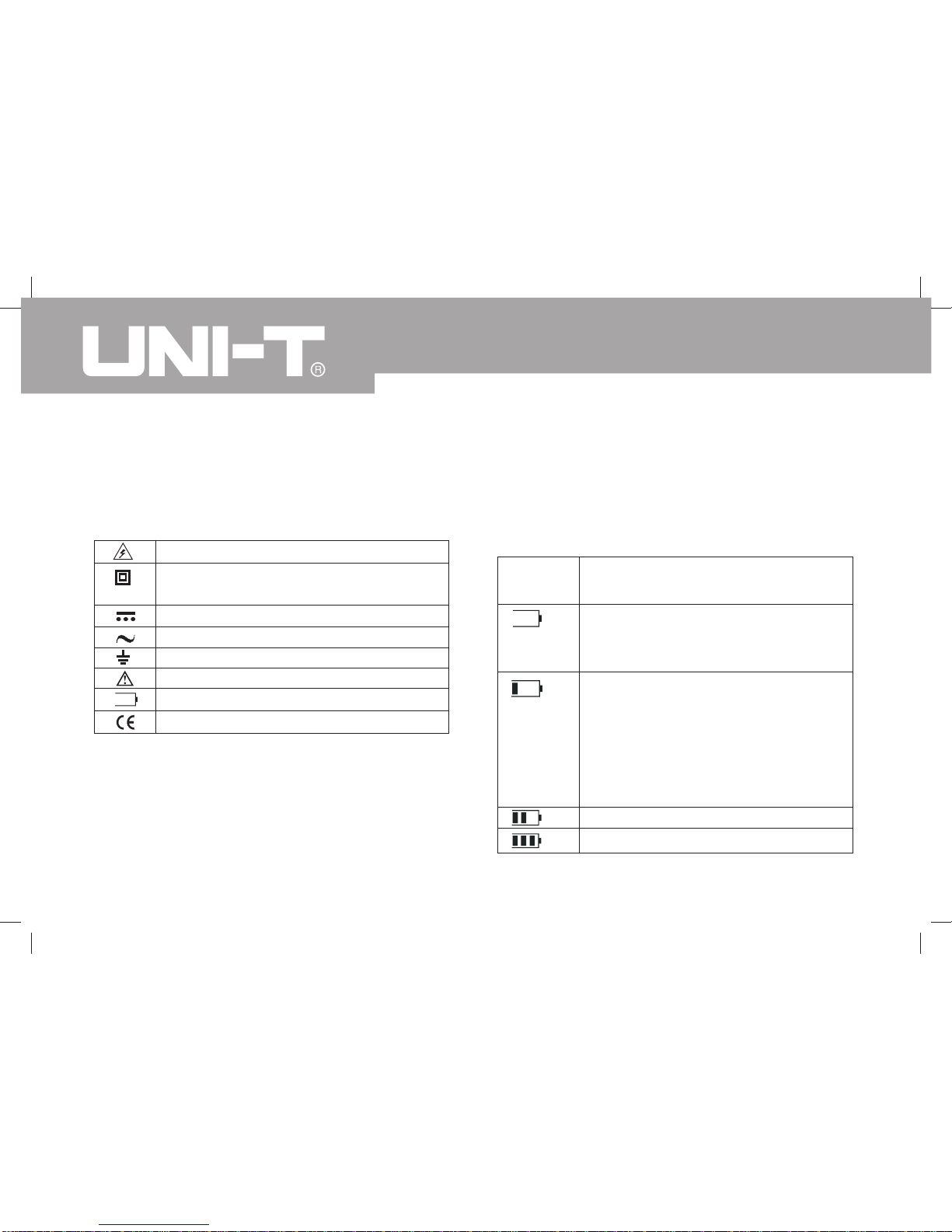
Do not use the Meter if the battery indicator
( ) shows a battery empty condition. Take
the battery out from the Meter if it is not used
for a long time.
Do not use or store the Meter in an
environment of high temperature, humidity,
explosive, inflammable and strong magnetic
field. The performance of the Meter may
deteriorate after dampened.
Soft cloth and mild detergent should be used
to clean the surface of the Meter when
servicing. No abrasive and solvent should be
used to prevent the surface of the Meter from
corrosion, damage and accident.
Dry the Meter before storing if it is wet.
When carrying out insulation measurement,
do not contact the circuit under test.

Risk of electric shock
Equipment protected by double or
reinforced insulation.
DC Measurement
AC Measurement
Grounding
See Manual
Empty of Built-In Battery
Conforms to Standards of European Union
8
Model UT513: OPERATING MANUAL
International Electrical Symbols
International symbols on the Meter and in this manual
are explained in Table 2.
Table 2. International Electrical Symbols
Battery Saver (Sleep Mode)
The Meter enters the Sleep Mode and blanks the display
if there is no button press for 15 minutes. This is done
to conserve battery power. The Meter comes out of
Sleep Mode when ON/OFF button is pressed and hold
for 1 second.
Battery Indication
There is a battery indicator shows on the display upper
left hand corner. Below Table 3 is the explanation:
Battery Voltage
10V or less. It means the battery is
empty, donít use the Meter as it cannot
guarantee accuracy.
10V~10.5V. It means the battery is
nearly empty, replacing battery is
necessary. At this status, the Meter can
still do 500V and 1000V output
measurement, accuracy will not be
affected.
10.6V~11.5V
11.6V or more
Table 3. Battery Indication
Battery
Indicator

9
Model UT513: OPERATING MANUAL
The Meter Structure
Below Figure 1 and Table 4 shows the Meter front
structure and description
Figure 1. The Meter Front Structure
Green Black Red

10
Model UT513: OPERATING MANUAL
1
2
3
4
5
6
7
8
9
10
11
12
13
14
15
16
Table 4. Meter Front Description
LCD
Scroll Button
Emergency Stop
Data Clear the Display Backlight Button
Down Button
On/Off Button
Compare Button
Insulation Resistance Button
DC Voltages measurement Button
Timer Button.
AC Voltages measurement Button
Test Button
USB Button
Data Store Button.
Data Recall Button
Scroll Button
17
18
19
20
21
22
Up Button
LINE: High Voltage output input terminal
(two plugs red test lead to one alligator clip)
High voltage line shielding input terminal
(two plugs red test lead to one alligator clip)
GUARD: Grounding protection input terminal
(one plug black test lead to one alligator clip)
EARTH: High resistance measurement input
terminal (one plug green test lead to one
alligator clip)
Testing leads:
Two plugs red test lead to one alligator clip.
One plug black test lead to one alligator clip.
One plug green test lead to one alligator
clip.

11
Model UT513: OPERATING MANUAL
Below Figure 2 and Table 5 shows the Meter side
structure and description
Figure 2. The Meter Side Structure
Table 5. Meter Side Description
1 Safety Shutter
2 Power adaptor Input Terminal
3 USB Port

12
Model UT513: OPERATING MANUAL
Display
Table 6 and Figure 3 describe the display.
Figure 3. Display

13
Model UT513: OPERATING MANUAL
Table 6. Display Description
Number
1
2
3
4
5
6
7
8
9
10
11
Meaning
Indicator for DC voltage
Indicator for data store full
Indicator for clearing
Indicator for AC voltage
Indicator for timer
Step symbol
Indicates selected pass/fail compare value
Indicates for negative reading
Timer 1 symbol
Timer 2 symbol
Data store is on
Number
12
13
14
15
16
17
18
19
20
21
Meaning
Data recall is on
Indicator for polarization index
Unit symbols
The continuity buzzer is on
Compare feature pass
Analogue bar graph
Risk of electric shock
Compare feature fail
Indicator for power adaptor
Battery life indicator

14
Model UT513: OPERATING MANUAL
Table 7. Key Description
Turn on or off the Meter. Press and
hold the button for 1 second to turn the
Meter on. Press again to turn off the
Meter.
The Meter default range is 500V
insulation resistance continuous
measurement when turning on.
Emergency stop button. Press this
button when the Meter is hang and
cannot turn off the power.
Press to turn on or off the display
backlight
Press and hold to clear the stored data
Press to store the current measurement
value. The maximum number of stored
reading is 18. When the stored readings
memory is full, the Meter shows FULL
and stop storing. Press and hold
CLEAR / to clear the stored value
in order to store the next measurement
value.
LOAD
Key Functions
ON/OFF
E-STOP
CLEAR /
SAVE
Press once to recall the first stored
value.
Press again to exit Load feature.
Load feature can only be used when
there is no high voltage output.
When the insulation resistance
measurement has no testing voltage
output, press to select one voltage
range up.
Under load mode: press to recall the
previous stored value.
When the insulation resistance
measurement has no testing voltage
output, press to select one voltage
range down.
Under load mode: press to recall the
next stored value.

15
Model UT513: OPERATING MANUAL
Table 7. Key Description
When set the timer duration for the
measurement of insulation resistance
or polarization index, press to
decrement the time. The maximum
length of time is 15 minutes and 30
seconds, the Meter will automatically
carry out measurement.
When compare feature measuring
insulation resistance, press to
decrement a resistance comparing
value.
After polarization index
measurement, press to display
polarization index, TIME 2 insulation
resistance value and TIME 1
insulation resistance value in
sequence.
When set the timer duration for the
measurement of insulation resistance
or polarization index, press to
increment the time. The maximum
length of time is 30 minutes and 30
seconds, the Meter will automatically
carry out measurement.
When use the compare feature
measuring insulation resistance,
press to increment a resistance
comparing value.
After polarization index
measurement, press to display
polarization index, TIME 2 insulation
resistance value and TIME 1
insulation resistance value in
sequence.
Press once to start the data
transferring to the computer via USB,
USB symbol shows on the display.
Press again to stop the data
transferring to the computer via USB,
USB symbol disappears.
USB

16
Model UT513: OPERATING MANUAL
Table 7. Key Description
Set a pass / fail limit for insulation tests.
The default value is 10M
Pres to step through continuous
measurement, timed measurement and
polarization index measurement in
sequence.
Press to stop or start an insulation
resistance test
Press to initiate insulation resistance
measurement
Press to initiate DC voltage
measurement
Pres to initiate AC voltage
measurement
COMP
TIME
TEST
IR
DCV
ACV

17
Model UT513: OPERATING MANUAL
Measurement Operation A. Measuring Voltages
Figure 4. Voltages Measurement
Below section explains how to make measurements.
Press and hold ON/OFF to turn on the Meter, press
again to turn off the Meter. The Meter default range is
500V insulation resistance continuous measurement
when turning on.
Red
Green

18
Model UT513: OPERATING MANUAL
To avoid harms to you or damages to the Meter,
please do not attempt to measure voltages
higher than 600V or 600V rms, although
readings may be obtained.
Special care should be taken when measuring
high voltage.
Operating Catuion
To measure voltages, set up the Meter as Figure 4 and
do the following:
Press DCV or ACV button to select DC voltage or
AC voltage measurement
Insert the red and green test lead into the tested
circuit.
When measuring DC voltage, if the red test lead is
negative voltage, ì-ì symbol will show on the display.
1.
2.
3.
When voltage measurement has been completed,
disconnect the connection between the testing
leads and the circuit under test and remove testing
leads away from the input terminals of the Meter.
Note

19
Model UT513: OPERATING MANUAL
Black
Red
B. Measuring Insulation Resistance
Figure 5. Insulation Resistance Measurement
Operating Caution
When performing insulation resistance tests,
remove all power from the circuit to be
measured and discharge all the power.
Operating the Meter must be very careful as it
outputs dangerous voltage during
measurement. Must make sure the tested object
is firmed clipped, hands are away from the
clips, then press TEST button to put high
voltage.
Do not short circuit the testing leads during
high voltages output or test insulation
resistance after high voltages output. This kind
of incorrect operating may cause sparking and
fire, which damages the Meter and harms to
you.
Do not measure over 10 seconds when:
500V measure resistance lower than 2M
1000V measure resistance lower than 5M
2500V measure resistance lower than 10M
5000V measure resistance lower than 20M
Green
Groud
Table of contents
Other Unit Multimeter manuals