Kyoritsu Electrical Instruments Works, Ltd. 6010A User manual

MODEL
6010A
MULTI-FUNCTION TESTER
INSTRUCTION MANUAL
KYORITSU ELECTRICAL INSTRUMENTS WORKS,LTD.
www.calcert.com [email protected]1.800.544.2843 0
5
10
15
20
25
30

1.Safe Testing .................................................................................. 1
2.Features ........................................................................................ 3
3.Specification .................................................................................. 6
4.Continuity (resistance) tests .......................................................... 9
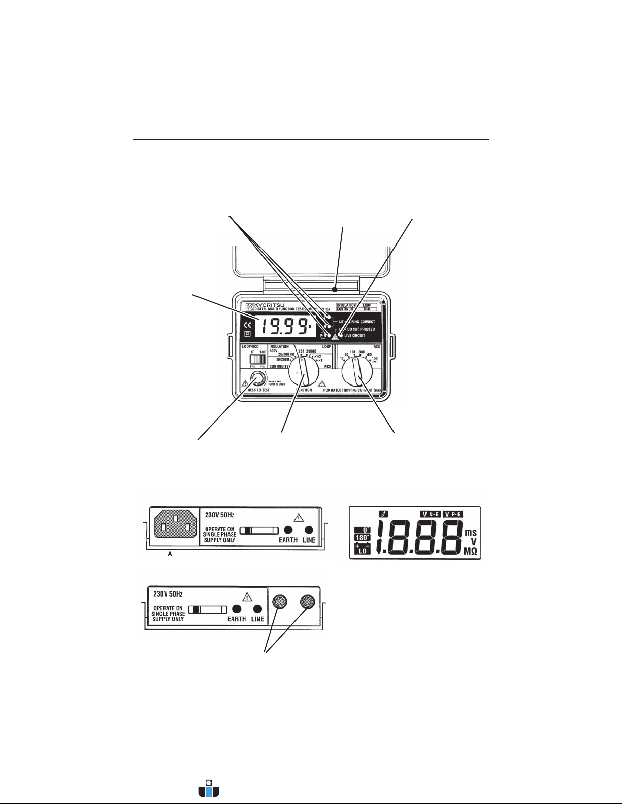
4.1
Instrument layout ................................................................. 9
4.2
Resistance of test leads ....................................................... 9
4.3
Continuity testing ............................................................... 10
5.Insulation Tests ........................................................................... 11
5.1
The nature of insulation resistance .................................... 11
5.1.2
Capacitive current .............................................................. 11
5.1.3
Conduction current ............................................................ 12
5.1.4
Surface leakage current ..................................................... 12
5.1.5
Total leakage current ......................................................... 13
5.2
Damage to voltage-sensitive equipment ............................ 13
5.3
Preparation for measurement ............................................ 14
5.4
Insulation resistance measurement ................................... 14
6.Loop Impedance Tests ............................................................... 17
6.1
Voltage measurement ........................................................ 17
6.2
What is earth fault loop impedance? ................................. 17
6.3
Automatic over-temperature cut-out .................................. 17
6.4
The loop impedance test ................................................... 18
6.5
Loop impedance at 3 phase equipment ............................. 19
7.RCD Tests ................................................................................... 21
7.1
Purpose of RCD Test ......................................................... 21
7.2
What does the RCD test really do? ................................... 21
7.3
RCD testing ....................................................................... 21
7.4
Testing RCDs used to provide supplementary protection .. 22
7.5
Testing time delayed RCDs ............................................... 22
8.General ....................................................................................... 23
9.Battery replacement .................................................................... 24
10.Fuse replacement ....................................................................... 24
11.Servicing ..................................................................................... 25
12.Case, strap and shoulder pad assembly ..................................... 26
CONTENTS
www.calcert.com [email protected]1.800.544.2843 0
5
10
15
20
25
30

—
1
—
1. SAFE TESTING #
Electricity is dangerous and can cause injury and death. Always treat it with
the greatest of respect and care. If you are not quite sure how to proceed, stop
and take advice from a qualified person.
●The symbol #on the instrument means that the user must refer to the
relevant section of this instruction manual for safe operation of the
instrument.
●
Pay particular attention to all WARNINGS and CAUTIONS in this instruction
manual.
WARNING indicates warnings to avoid electric shock and CAUTION indicates
cautions to avoid damage to the instrument.
1.
This instrument must only be used by a competent and trained person and
operated in strict accordance with the instructions. KYORITSU will not
accept liability for any damage or injury caused by misuse or non-
compliance with the instructions or with the safety procedures.
2.
It is essential to read and to understand the safety rules contained in the
instructions. They must always be observed when using the instrument.
3.
This instrument is intended only for single phase operation at 230V AC ±
10% phase to earth or phase to neutral operation, and then only for loop
and RCD testing. For use in the continuity testing and insulation testing
modes this instrument
must be used ONLY on circuits which are de-
energised.
4.
When conducting tests do not touch any exposed metalwork associated
with the installation. Such metalwork may become live for the duration of
the test.
5.
Never open the instrument case (except for fuse and battery replacement
and in this case disconnect all leads first) because dangerous voltages are
present. Only fully trained and competent electrical engineers should open
the case. If a fault develops, return the instrument to your distributor for
inspection and repair.
6.If the overheat symbol appears in the display ( ) disconnect the
instrument from the mains supply and allow to cool down.
7.
For loop impedance tests to prevent unwanted tripping during loop testing
all residual current devicesRCD'smust be taken out of the circuit and
temporarily replaced with a suitably rated MCB unit. The RCD must be
replaced after the loop test is completed.
www.calcert.com [email protected]1.800.544.2843 0
5
10
15
20
25
30

—
2
—
8.
If abnormal conditions of any sort are noted (such as a faulty display,
unexpected readings, broken case, cracked test leads, etc) do not use the
tester and return it to your distributor for repair.
9.
For safety reasons only use accessories (test leads, probes, fuses, cases,
etc) designed to be used with this instrument and recommended by
KYORITSU. The use of other accessories is prohibited as they are unlikely
to have the correct safety features.
10.When testing, always be sure to keep your fingers behind the safety
barriers on the test leads.
11.
During testing it is possible that there may be a momentary degradation of
the reading due to the presence of excessive transients or discharges on
the electrical system under test. Should this be observed, the test must be
repeated to obtain a correct reading. If in doubt, contact your distributor.
12.
The sliding shutter on the back of the instrument is a safety device. The
instrument should not be used if it is damaged or impaired in any way, but
returned to your distributor for attention.
13.
Do not operate the function selector whilst the instrument is connected to
a circuit. If, for example, the instrument has just completed a continuity
test and an insulation test is to follow, disconnect the test leads from the
circuit before moving the selector switch.
14.
Do not rotate function dial when test button is depressed. If the function
switch is inadvertently moved to a new function when the test button is
depressed or in lock-down position the test in progress will be halted. To
reset, release test button and press again to restart testing on new
function.
15.
Use a damp cloth and detergent for cleaning the instrument. Do not use
abrasives or solvents.
16.
Before using the instrument, please insert the batteries rightly in
accordance with the "9. BATTERY REPLACEMENT" of page 24.
When not installing batteries, all the functions of the instrument don't
work.
www.calcert.com [email protected]1.800.544.2843 0
5
10
15
20
25
30

—
3
—
2. FEATURES
FUNCTION SWITCH
TEST BUTTON
RCD RATED TRIPPING
CURRENT SWITCH
LIVE CIRCUIT LED
CONNECTOR
WIRING CHECK
LED
LCD DISPLAY
Test Lead with IEC Connector LCD DISPLAY
Test Lead for Continuity and Insulation Testing
Fig 1
www.calcert.com [email protected]1.800.544.2843 0
5
10
15
20
25
30

—
4
—
Model 6010A Multi-Function tester performs five functions in one instrument.
1.Continuity tester
2.Insulation resistance tester
3.Loop impedance tester
4.RCD tester
5.
Mains voltage warning when operating the loop impedance and RCD
mode.
The tester is designed to Safety Standard IEC 61010-1
/
EN 61010-1 CAT III
(300V).
Dust proof construction in conformance with IP50, IEC529.
The instrument is supplied with:
-
1.A KAMP10 lead for loop/RCD testing at socket outlets.
2.MODEL7122B lead for insulation and continuity testing.
In the insulation resistance testing mode the instrument provides a rated current
of 1mA as required in
IEC 61557-2
/
EN 61557-2 1997.
In the continuity testing mode the instrument provides a short circuit current of
200mA as required in
IEC 61557-4
/
EN 61557-4 1997.
Continuity and insulation resistance functions have the following features:-
Live circuit warning A colour coded LED warns if the circuit under
test is live.
Auto discharge Electric charges stored in capacitive circuits
are discharged automatically after testing by
releasing the test button.
Test current Warning Beeper Warns when the test current exceeds
200mA
(IEC 61557-4) during continuity measurement.
Loop impedance and RCD testing functions have the following features:-
Voltage level In the loop impedance mode, supply voltage
is displayed when the instrument is connected
to the supply until the test button is pressed.
Wiring check Three LEDs indicate if the wiring of the circuit
under test is correct.
www.calcert.com [email protected]1.800.544.2843 0
5
10
15
20
25
30

—
5
—
Over temperature protection Detects overheating of the internal resistor
(used for loop and RCD tests) and of the
current control MOS FET (used for RCD
tests) displaying a warning symbol ( ) and
automatically halting further measurements.
Phase angle selector The test can be selected from either the
positive (0°
) or from the negative (180°
) half-
cycle of voltage. This will prevent tripping of
some polarised RCDs when loop testing and
may give a more accurate reading when
testing RCDs.
Auto data hold Holds the displayed reading for a time after
the test is complete.
Auto power off Automatically switches the instrument off after
a period of approximately 1 minutes.
V-NE Monitoring Circuit Automatically aborts measurement when the
N-E voltage rises to 50V or greater on RCD
ranges.
Optional Accessory OMA DIEC distribution board or lighting circuit
test lead for LOOP
/
RCD testing.
www.calcert.com [email protected]1.800.544.2843 0
5
10
15
20
25
30

—
6
—
Open Circuit
Voltage(DC)
Short Circuit
Current Range Accuracy
Greater than 4V Greater than
200mA
20/200Ω
Auto-Ranging
Up to 2Ω ±(3%rdg+4dgt)
Over 2Ω ±(3%rdg+3dgt)
Operating range(as in IEC61557) 20Ωrange:0.2Ω〜19.99Ω/200ΩRange:20Ω〜199.9Ω
Insulation Resistance (to IEC61557-2)
Open Circuit
Voltage (DC) Rated Current Range Accuracy
500V +20%−0% 1mA or greater
@ 500kΩ
20/200MΩ
Auto-Ranging ±(3% rdg +3dgt)
Operating range(as in IEC61557) 20MΩ Range:0.5MΩ〜19.99MΩ/200MΩ Range:20MΩ〜100MΩ
Loop Impedance (to IEC61557-3)
Rated Voltage
(AC)
Nominal Test
Current at 0Ω
External Loop
Range Accuracy
230V+10%-15%
50Hz
25A/10ms 20Ω ±(3%rdg +8dgt)
15mA/350ms max. 2000Ω ±(3%rdg +8dgt)
Operating range(as in IEC61557) 20Ω Range:2Ω〜19.99Ω/2000Ω Range:100Ω〜1999Ω
RCD testing (to IEC61557-6)
Function
Rated Voltage
(AC)
Trip Current
Settings
Trip Current
Duration Accuracy
RCD ×1/2
230V+10%-15%
50Hz
10/30/100/300/
500mA 2000ms
Trip Current:
-8% 〜-2% Trip Time
±(1%rdg+3dgt)
RCD ×1 Trip Current:
+2% 〜+8%
FAST 150mA 50ms
Voltage Measurement
Rated Voltage Measuring Range Accuracy
100〜250V 50Hz 100〜250V 50Hz 3%rdg
3. SPECIFICATION
Measurement Specification
Continuity (to IEC61557-4)
www.calcert.com [email protected]1.800.544.2843 0
5
10
15
20
25
30

—
7
—
To prevent wrong connection of test leads and to maintain safety, the
dedicated terminals used for continuity and insulation tests are automatically
covered when using the terminals for loop impedance and RCD tests
Instrument dimensions 175 X 115 X 86mm
Instrument weight 780g including batteries.
Reference conditions Specifications are based on the following
conditions except where otherwise stated:-
1.Ambient temperature: 23±5℃
2.Relative humidity: 45% to 75%
3.Position: horizontal
4.AC power source: 230V, 50Hz
5.DC power source: 12.0 V, ripple content 1%
or less
6. Altitude: Up to 2000m
Battery type Eight R6 or LR6 batteries.
Low battery warning "" symbol appears in the display if the battery
voltage drops below 8V.
Maximum numbers of Approx. 700 times for use by continuity range or
measurements approx. 1000 times for use by insulation resistance
range.
Operating temperature 0 to +40℃, relative humidity 80% or less, no
and humidity. condensation.
Storage temperature -10 to +50℃, relative humidity 75% or less, no
and humidity condensation.
Illuminates if there is an alternating voltage of 20V
AC or more in the circuit under test before
continuity or insulation resistance tests. When DC
voltage is detected across the measuring terminal
the LED lights up.
The P-E and P-N LEDs illuminate when the wiring
of the circuit under test is correct. The reverse
lamp is lit when P and N are reversed.
Auto data hold In the loop impedance and RCD test functions, the
LCD reading is automatically frozen for 5 seconds
after measurement.
Display The liquid crystal display has 3 1/2 digits with a
decimal point and units of measurement (Ω, MΩ,
V and ms) relative to selected function. The display
LED indication of
live circuit warning
LED indication of correct
Polarity
www.calcert.com [email protected]1.800.544.2843 0
5
10
15
20
25
30

—
8
—
is updated approximately five times per second.
Overload protection The continuity test circuit is protected by a 0.5 A
600 V fast acting(HRC)ceramic fuse mounted in
the battery compartment, where a spare fuse is
also stored.
The insulation resistance test circuit is protected by
a resistor against 600 V AC for 10 seconds.
Mains Voltage Indication On connecting test leads to the circuit under test
on Loop and RCD ranges, the LCD reads V-PE.
Sign "V-PE Lo" or "V-PE Hi" is also shown when
the voltage is 100V or less, or 260V or greater
respectively.
Equipment protected throughout by DOUBLE
INSULATION or REINFORCED INSULATION.
Caution, risk of electric shock.
#Caution(refer to accompanying instruction
manual)
.
Symbols used on the
instrument
www.calcert.com [email protected]1.800.544.2843 0
5
10
15
20
25
30

—
9
—
4. CONTINUITY(RESISTANCE)TESTS
# WARNING
ENSURE THAT CIRCUITS TO BE TESTED ARE NOT LIVE.
DISCONNECT THE INSTRUMENT FROM THE CIRCUIT UNDER TEST
BEFORE OPERATING THE FUNCTION SWITCH.
TO SELECT THE LOW RESISTANCE RANGE SELECT“CONTINUITY”
4.1
Instrument layout See Fig 1.
4.2
Resistance of test leads
The object of testing is to measure the resistance of parts of the wiring system
alone,and this should not include the resistance of any test leads used.The
procedure is to measure the resistance of the test leads and to subtract this
from the instrument reading which includes the lead resistance.Proceed as
follows:-
1.Press the test button once. Then, the instrument switches on.
2. Connect the ends of the test leads in use firmly together(see Fig 2)and
operate the test button.
3.The display will read the resistance of the test leads,and a careful note
should be made of the reading.
Fig 2
www.calcert.com [email protected]1.800.544.2843 0
5
10
15
20
25
30

—
10
—
4.3
Continuity testing
1.Press the test button once. Then, the instrument switches on.
2.Select the continuity test by rotating the function dial.
3. Connect the test leads to the circuit whose resistance is required(see Fig
3)HAVING FIRST MADE SURE THAT THE CIRCUIT IS NOT LIVE.
Note that the live circuit warning lamp will illuminate if the circuit is live
-
but
check first anyway!
4.Press the test button and read the circuit resistance from the display.
5. Note that if the circuit resistance is greater than 20 Ω the instrument will
autorange to the 200 Ω range.
6.Subtract the test lead resistance(measured in 4.2 above)from the
display reading.
7.The result will be the resistance of the circuit under test.
Note: If the reading is greater than 200Ω the over range symbol "OL" will
remain displayed.
The results of measurements can be adversely affected by impedances
of additional operating circuits connected in parallel or by transient
currents.
Fig 3
www.calcert.com [email protected]1.800.544.2843 0
5
10
15
20
25
30

—
11
—
5. INSULATION TESTS
# WARNING
ENSURE THAT CIRCUITS TO BE TESTED ARE NOT LIVE.
DISCONNECT THE INSTRUMENT FROM THE CIRCUIT UNDER TEST
BEFORE OPERATING THE FUNCTION SWITCH.
TO SELECT THE INSULATION RESISTANCE RANGE SELECT
“INSULATION”
5.1
The nature of insulation resistance
Live conductors are separated from each other and from earth metal by
insulation, which has a resistance which is high enough to ensure that the
current between conductors and to earth is kept at an acceptably low level.
Ideally insulation resistance is infinite and no current should be able to flow
through it. In practice, there will normally be a current between live conductors
and to earth, and this is known as leakage current. This current is made up of
three components, which are:-
1. capacitive current
2. conduction current, and
3. surface leakage current.
5.1.2
Capacitive Current
The insulation between conductors which have a potential difference between
them behaves as the dielectric of a capacitor, the conductors acting as the
capacitor plates. When a direct voltage is applied to the conductors, a charging
current will flow to the system which will die away to zero (usually in less than
a second) when the effective capacitor becomes charged. This charge must be
removed from the system at the end of the test, a function which is
automatically performed by Model 6010A. If an alternating voltage is applied
between the conductors, the system continuously charges and discharges as
the applied voltage alternates, so that there is a continuous alternating leakage
current flowing to the system.
www.calcert.com [email protected]1.800.544.2843 0
5
10
15
20
25
30

—
12
—
Fig 4
5.1.3
Conduction Current
Since the insulation resistance is not infinite, a small leakage current flows
through the insulation between conductors. Since Ohm's Law applies, the
leakage current can be calculated from
Leakage current (μA) = applied voltage (V)
insulation resistance (MΩ)
Fig 5
5.1.4
Surface Leakage Current
Where insulation is removed, for the connection of conductors and so on,
current will flow across the surfaces of the insulation between the bare
conductors. The amount of leakage current depends on the condition of the
surfaces of the insulation between the conductors. If the surfaces are clean
and dry, the value of the leakage current will be very small. Where the
surfaces are wet and/or dirty, the surface leakage current may be significant. If
it becomes large enough, it may constitute a flashover between the conductors.
Whether this happens depends on the condition of the insulation surfaces and
on the applied voltage; this is why insulation tests are carried out at higher
voltages than those normally applying to the circuit concerned.
Fig 6
www.calcert.com [email protected]1.800.544.2843 0
5
10
15
20
25
30

—
13
—
5.1.5
Total Leakage Current
The total leakage current is the sum of the capacitive, conduction and surface
leakage current described above. Each of the currents, and hence the total
leakage current, is affected by factors such as ambient temperature, conductor
temperature, humidity and the applied voltage.
If the circuit has alternating voltage applied, the capacitive current (5.1.2) will
always be present and can never be eliminated. This is why a direct voltage is
used for insulation resistance measurement, the leakage current in this case
quickly falling to zero so that it has no effect on the measurement. A high
voltage is used because this will often break down poor insulation and cause
flashover due to surface leakage (see 5.1.4), thus showing up potential faults
which would not be present at lower levels. The insulation tester measures the
applied voltage level and the leakage current through the insulation. These
values are internally calculated to give the insulation resistance using the
expression:-
Insulation resistance (MΩ) = Test voltage (V)
Leakage current (μA)
As the capacitance of the system charges up, so the charging current falls to
zero and a steady insulation resistance reading indicates that the capacitance
of the system is fully charged. The system is charged to the full test voltage,
and will be dangerous if left with this charge. Model 6010A provides an
automatic path for discharging current as soon as the test button is released to
ensure that the circuit under test is safely discharged.
If the wiring system is wet and/or dirty, the surface leakage component of the
leakage current will be high, resulting in low insulation resistance reading. In
the case of a very large electrical installation, all the individual circuit insulation
resistances are effectively in parallel and the overall resistance reading will be
low. The greater the number of circuits connected in parallel the lower will be
the overall insulation resistance.
5.2
Damage to Voltage-Sensitive Equipment
An increasing number of electronic-based items of equipment are being
connected to electrical installations. The solid state circuits in such equipment
are likely to be damaged by the application of the levels of voltage used to test
insulation resistance. To prevent such damage, it is important that voltage-
sensitive equipment is disconnected from the installation before the test is
carried out and reconnected again immediately afterwards. The devices which
may need to be disconnected before the test include:-
www.calcert.com [email protected]1.800.544.2843 0
5
10
15
20
25
30

—
14
—
◦Electronic fluorescent starter switches
◦Passive infra-red detectors (PIRs)
◦Dimmer switches
◦Touch switches
◦Delay timers
◦Power controllers
◦Emergency lighting units
◦Electronic RCDs
◦Computers and printers
◦Electronic point-of-sale terminals (cash registers)
◦Any other device which includes electronic components.
5.3
Preparation for measurement
Before testing, always check the following:-
1.The“low battery”Indication“”is not displayed
2.There is no visually obvious damage to the tester or to the test leads
3.Test the continuity of the test leads by switching to continuity test and
shorting out the lead ends. A high reading will indicate that there is a faulty
lead or that the fuse is blown.
4.
MAKE SURE THAT THE CIRCUIT TO BE TESTED IS NOT LIVE.
A warning lamp is lit if the instrument is connected to a live circuit but test
the circuit as well!
5.4
Insulation resistance measurement
Model 6010A has a single test voltage of 500V DC.
1.Press the test button once. Then, the instrument switches on.
2.Select the insulation resistance setting by rotating the function dial to
“insulation”test section of the functional switch, after making sure that the
instrument is not connected to a live circuit.
3.Attach the test leads to the instrument and to the circuit or the appliance
under test (see Figs 7 & 8)
www.calcert.com [email protected]1.800.544.2843 0
5
10
15
20
25
30

—
15
—
Fig 7
4.If the mains warning lamp lights and/or the buzzer sounds DO NOT PRESS
THE TEST BUTTON but disconnect the instrument from the circuit. Make
the circuit dead before proceeding.
Fig 8
5.Press the test button when the display will show the insulation resistance of
the circuit or the appliance to which the instrument is connected.
6.Note that if the circuit resistance is greater than 20MΩthe instrument will
automatically range to the 200MΩreading.
www.calcert.com [email protected]1.800.544.2843 0
5
10
15
20
25
30

—
16
—
7.When testing is complete release the test button BEFORE disconnecting
the test leads from the circuit or from the appliance. This will ensure that
the charge built up by the circuit or the appliance during insulation test is
dissipated in the discharge circuit. In the discharging process, an LED
illuminates and the live circuit warning buzzer will sound.
# CAUTION
NEVER TURN THE FUNCTION DIAL WHILST THE TEST BUTTON
IS DEPRESSED AS THIS MAY DAMAGE THE INSTRUMENT.
NEVER TOUCH THE CIRCUIT, TEST LEAD TIPS OR THE
APPLIANCE UNDER TEST DURING INSULATION TESTING.
Note:If the reading measured greater than 200MΩ the over range reading
“OL”will be displayed.
www.calcert.com [email protected]1.800.544.2843 0
5
10
15
20
25
30

—
17
—
○
Even though the test current in the 2000 ohm range (15mA test current) is
low some RCD's may trip due to sensitivity or where there may already be
additional leakage in the circuit being tested.
○
The Loop impedance in a TN system is small and therefore it is not
recommended to test in the 2000 ohm range. RCD's will have to be bridged
to avoid tripping when using other test ranges.
6. LOOP IMPEDANCE TESTS
DISCONNECT THE INSTRUMENT FROM THE CIRCUIT UNDER TEST
BEFORE OPERATING THE FUNCTION SWITCH
TO SELECT THE LOOP TESTING RANGE SELECT“LOOP”
6.1
Voltage Measurement
Press the test button once. Then, the instrument switches on.When the tester
is set to the loop test function, mains voltage is displayed as soon as the
instrument is connected for test. This voltage display is automatically updated
five times every second. The voltage function operates whenever the test
button is in the up position.
6.2
What is earth fault loop impedance?
The path followed by fault current as a result of a low impedance fault
occurring between the phase conductor and earth is called earth fault loop.
Fault current is driven round the loop by the supply voltage, the amount of
current depending on the voltage of the supply and on the impedance of the
loop. The higher the impedance, the lower will be the fault current and the
longer it will take for the circuit protection (fuse or circuit breaker) to operate
and interrupt the fault.
To make sure that fuses will blow or that circuit breakers will operate quickly
enough in the event of a fault, the loop impedance must be low, the actual
maximum value depending on the characteristics of the fuse or the circuit
breaker concerned. Every circuit must be tested to make sure that the actual
loop impedance does not exceed that specified for the protective device
concerned.
6.3
Automatic over-temperature cut-out
During the short test period the instrument dissipates power of about 6 kW. If
frequent tests are conducted over a prolonged period of time, the internal test
www.calcert.com [email protected]1.800.544.2843 0
5
10
15
20
25
30

—
18
—
resistor will overheat. When this happens, further tests are automatically
inhibited and the over-temperature symbol ( ) appears in the display. The
instrument must then be left to cool down, when testing may be resumed.
6.4
The loop impedance test
Since the earth fault loop is made up of conducting path which includes the
supply system back to the supply transformer, it follows that loop testing can
only be carried out after the mains supply has been connected. In many cases,
any RCD in the circuit will be tripped by this test, which draws current from the
phase and returns it through the earth system. The RCD will see this as the
type of fault it is designed to protect against, and will trip. To prevent this
unwanted RCD tripping during loop testing, any RCD must be taken out of
circuit and temporarily replaced with a suitably rated MCB unit. The RCD will
need to be replaced after the loop test is completed.
# WARNING
DO NOT PROCEED WITH TESTING UNLESS THE P-E AND P-N
LAMPS ARE LIT TO CONFIRM THAT THE WIRING IS CORRECTLY
CONNECTED. Should these two lamps not be lit, investigate the
wiring connections of the installation and rectify any faults before
proceeding with the test. If the LED is lit do not proceed.
1.Press the test button once. Then, the instrument switches on.
2.Set the instrument to loop test 20Ωrange.
3.If testing sockets, connect the plug lead to the Model 6010A and push the
moulded plug into the socket to be tested (see Fig 9).
4.Check the wiring lamps are lit (see above).
5.Note the mains voltage displayed by the instrument.
6.Press the“Press to test”button. The value of the measured loop
impedance will be displayed with the appropriate units.
7.If testing lighting or other circuits, connect the three-wire lead OMA DIEC to
Model 6010A, connect the red (phase) lead to the phase connection of the
circuit under test, connect the black (neutral) lead to the neutral connection
of the circuit under test, and connect the earth lead to the earth associated
with the circuit. (see Fig 10).
8.If any RCD associated with the circuit trips out, reset the RCD and try
testing again, this time operating the phase selector switch once prior to
pressing the test button. This will change the period of the waveform over
www.calcert.com [email protected]1.800.544.2843 0
5
10
15
20
25
30
Table of contents
Other Kyoritsu Electrical Instruments Works, Ltd. Multimeter manuals