IMER USA MORTARMAN 360 A MortarMixer User manual
IMER INTERNATIONAL S.p.A.
MIX 360
1
MORTARMAN® 360"A" MortarMixer
INSTRUCTION MANUAL and PARTS LIST
MANUAL DE USO, MANTENIMIENTO y RECAMBIOS
Machine serial N°
Part. number 3211378 R02 - 2018/09

Thank you for purchasing a Mortarman® 360 from an IMERU.S.Adealer.
Your decision is an intelligent one. There is no other mortar mixer in the world which delivers the
benets
and features of the Mortarman® 360:
- Revolutionary horizonal mixing action.
- Oil bath gearbox, plenty of torque to mix materials wet or dry.
- Full width fenders and independent suspension ......standard gas or electric motors can be swapped
back and forth in under an hour.
- Advance drum and paddle design, excellent mixing and discharge action.
- Telescopic foot stands which provide additional stability during operation.
- Reduced Maintenance ....no zerks to grease or bearings to pack.
At IMER U.S.A we continually search for ways to better serve our customers.
Should you have an idea or thought to share with us regarding thisproduct we would apppreciate
hearing
from you. Our motto is "Tools and Services for the 21st Century". We look forward to deliveringthe
goods.
Thank you again for your purchase,
Mace T. Coleman Jr.
President, Imer U.S.A. Inc.
3654 EnterpriseAvenue
Hayward , 94545 California
Toll Free (800) 275-5463
Ofce: (510) 670-7970
Fax (510) 783-4255
IMER INTERNATIONAL S.p.A.
MIX 360
3
IMPORTANT
MIXING INSTRUCTIONS
AGGREGATE BIGGER THAN 1/8" WILL DAMAGE MIXER
SAND SILO
LIME
CEMENT
PRE - MIX 60 lb
SPEC - MIX 80 lb
SILO
Set up mixer
Start mixer
Do not add water
1. Add 1/2 sand
2. Add lime
3. Add cement
4. Mix materials dry
5. Add 3/4 of water
6. Add rest of sand
7. Add rest of water
8. Mix up thoroughly
Set up mixer
Start mixer
Do not add water
1. Check bag weight
2. Determinate max load
3. Add 1/2 of max load
4. Add 3/4 of water
5. Add rest of bags
6. Mix up thoroughly
Set up mixer
Start mixer
Do not add water
1. Add 1/2 of max load
2. Add 3/4 of water
3. Add rest of material
4. Add rest of water
5. Mix up thoroughly
MIXER DRUMCAPACITY
120:4.5 CUBIC FEET (250 lbs)*
240:9 CUBIC FEET (400 lbs)*
360:13 CUBIC FEET (700 lbs)*
750:27 CUBIC FEET (1700 lbs)*
* WEIGHT IS COMBINED SAND, LIME, AND CEMENT MIXTURE

IMER INTERNATIONAL S.p.A.
MIX 360
4
Dear customer,
congratulations on your choice of purchase: the IMER cement mixer, the
result of years of experience, is a very reliable machine equipped with all
the latest technical innovations.
The machine can mix both dry or wet ne grain materials (plaster, mor-
tar, cement, oor sub-bases, rendering, synthetic resins or pre-packed
mixes).
WORKING IN SAFETY
In order to be able to work in complete safety, the following instruc-
tions must be read carefully
- This OPERATING AND MAINTENANCE manual must be kept on site
by the person responsible for the site, e.g. the SITE FOREMAN, and
must always be available for consultation.
- The manual should be considered as being an integral part of the ma-
chine, and must be kept for future reference (EN 292/2) until the ma-
chine itself is disposed of. If the manual becomes damaged or lost, a
replacement can be obtained from the manufacturer.
- The manual contains important information regarding the preparation
of the site, installation and use of the machine, maintenance and spare
parts ordering. Nevertheless, the installer and operator must both have
adequate experience and knowledge of the machine.
- In order that the safety of the operator, safe working and long life of
the equipment can all be guaranteed, the instructions in this manual
must be followed together with safety standards and health and safety
at work laws currently in force (use of suitable footwear and clothing,
use of helmets, gloves and goggles, etc. in accordance with S.I N° 3073
of 30/11/92.
. ALWAYS MAKE SURE THAT SIGNS ARE LEGIBLE
. It is strictly forbidden to carry out any form of modication to
the structure or working parts of the machine.
IMER International decline any responsibility in the case of non-compli-
ance with laws and standards governing the use of this equipment. In
particular: improper use, defective power supply, lack of maintenance,
unauthorised modications, partial or total failure to observe instructions
contained in this manual.
1. DESIGN STANDARDS
The MIX360 mixer has been designed and constructed in accordance
with the following standards:
IEC 34.1; IEC 34.5; EN292-1,EN292-2,EN60204-1.
2. NOISE EMISSION LEVEL
Table 2 indicates the noise level produced by the mixer, measured at
the operator’s ear (LpA at 1 m - 98/37CE) and the environmental noise
emission level (power LWA) measured in accordance with EN ISO 3744
(2000/14/CE).
TABLE 2
TYPE OF MOTOR LpA(dB) LWA(dB)
ELECTRIC 70 81
ENGINE 88 103
3. MIXING CAPACITY
The mixing capacity of the machine per cycle is 200 litres (approximate-
ly half of the tank height).
4. SAFETY MEASURES
-The IMER cement mixer can only function if all the safety devices with
which it is equipped are in perfect condition.
-The machine will not operate if the mains connection is defective.
-On-site power connection lines must be installed so that they cannot
be damaged. Do not stand the machine on the mains connection line.
-The power lines must be installed so that water cannot penetrate con-
nections. Only use connectors tted with protection against water spray.
-Repairs to the electrical plant must only be carried out by specialised
personnel. Do not operate the mixer during maintenance or repair op-
erations.
-Accident prevention and health and safety at work regulations must be
complied with in the working area.
. The machine must only be stopped using the appropriate
switch.
. Do not open the tank protection cover to stop the machine.
5. ELECTRICAL SAFETY
The IMER mixer complies with standards EN60204-1. In particular, it is
equipped with a system that prevents automatic restart after the power
supply line is interrupted.
-Residual current protection of electrical equipment
-Electrical safety device that prevents the machine from operating when
the tank protection cover is open.
When used on construction sites, the mixer can be connected to an
earthing system by attaching an earthing braid (or wire) of minimum
section 16 mm² (see Fig. 2).
6. MECHANICAL SAFETY
-A guard over the outlet prevents access to the mixing zone.
-The tank protection cover allows the mix components to be loaded with-
out access to the mixing zone.
The mixer will stop if the cover is opened.
7. TRANSPORT
. WARNING!! Always disconnect the machine from the mains
before moving it.
-When on-site, the mixer can be moved manually from one location to
another as shown in Fig. 3.
-For other types of handling, the mixer must be lifted using a four-cable
sling attached to the lifting lugs, as shown in Fig. 4.
8. INSTALLATION
Lift the mixer (the mixer is tted with a lifting jack - ref. 4, g. 7).
- Screw in the outlet opening handle (see Fig. 6).
If there are no lifting means available, lift the mixer using the jack sup-
plied (see Fig. 7).
1 - Raise the rear supporting legs (Ref. 2 Fig. 7) to their maximum height
and lock them in position using the locking pins.
2 - Use the handle (Ref. 1 Fig. 7) to raise the machine, resting it on the
rear legs (Ref. 2 Fig. 7).
3 - Position the front legs (Ref. 3 Fig. 7) (towing side) at the height re-
quired and lock them using the locking pins.
4 - If the machine is to be positioned at maximum height, insert the lower
lug (Ref. 5 Fig. 7) in the support (Ref. 7 Fig. 7), raise and lock the rear
legs (Ref. 2 Fig. 7) at the third hole from the bottom.
5 - Remove the lower fork connection Ref. 5 and lower the jack so that
the upper fork connection can be inserted (Ref. 6 Fig. 7), then complete
the lifting operation.
For intermediate working levels, the rear part of the machine should be
lifted in a single operation, as in points 1 and 2, by using the lower con-
nection point on the jack (Ref. 5 Fig. 7).
To return the machine to the towing position, follow this procedure in
reverse order.
Position the machine on level ground, adjusting the telescopic legs to
the required height.
Ensure that the machine is in a stable working position.
9. USE
-Do not allow other people to remain in the vicinity of the machine dur-
ing operation.
-Do not use the machine in a re-risk zone. Sparks may cause res or
explosions.
-Always switch off the machine before leaving it unattended.
-The machine must only be transported or positioned with the motor
switched off.
9.1 START-UP
9.1.1 ELECTRICAL CONNECTION
-Check that the supply voltage is the same as dataplate specications.
-Ensure that the power supply line is tted with a differential protection
device upstream.
-Connect the machine to the earthing plant and the mains power supply.
-Ensure that the blades rotate in a clockwise direction.
If the paddles rotate in an anti-clockwise direction, stop the machine,
disconnect the mains plug and invert one of the phases inside the plug,
by rotating the inverter slot between the pins using a screwdriver (Fig.
8).
- Start the motor by pressing the black on/off pushbutton on the control
panel.
9.1.2 ENDOTHERMIC MOTOR
-Check the motor (see motor manual).
-Check the motor oil level (see motor manual).
-Fill the fuel tank (see motor manual).

IMER INTERNATIONAL S.p.A.
MIX 360
5
-Start the motor, following the instructions contained in the motor man-
ual.
-Allow the motor to warm up at reduced rpm.
-Increase the rpm to maximum using the accelerator lever mounted on
the frame.
Machines with an endothermic motor are tted with a centrifugal ex-
panding clutch mounted on the motor.
The clutch enables the paddle rotation speed to be increased gradually,
which can be stopped when the motor is operating at minimum rpm.
Motor operating speed can be controlled by means of the accelerator
lever (rif. 5, tab. 9).
9.2 WORKING CYCLE
. WARNING! Check that the machine stops rotating when the
tank protection cover is lifted.
Start-up the machine with the tank empty.
-With the water supply connected to the mains, start feeding water by
opening the valve mounted on the tank, and add the cement and ag-
gregate.
-The tank protection grid is tted with a bag splitter to enable pre-packed
mixes to be used.
-When the mix has reached the required consistency, place a suitable
container under the outlet and, keeping the paddles moving, open the
outlet using lever Ref. 1 (see Fig. 9).
Lift the lever to position A and push it as far as possible to position B.
To close the outlet, return the lever to Pos. C.
. Avoid starting the machine with a full load.
Do not overll the tank (see 3. MIXING CAPACITY).
10. EMERGENCY STOP
. In the event an electric motor fault, press the OFF pushbutton
(Ref. 17 Fig. 1) and disconnect the mixer from the power supply.
In the case of endothermic motors, move the acceleration lever to
the minimun position.
. The motor is protected from thermal overloads. If it overheats
it will stop. It must be allowed to cool before restarting.
11. MAINTENANCE
. WARNING! Before carrying out any form of maintenance
work, always switch off the mixer.
-Replace worn or faulty components using original spare parts.
-Check the oil level through the transparent level indicator on the side of
the reduction gear casing.
-Change the oil in the reduction gear with SAE 90 oil after 2000 hours of
work (approximately 0.9 Kg).
-To top up or replace the oil, used the ller pipe (ref. 1, g. 10). Lift the
motor casing to gain access to the ller.
. Used oil is classied as special waste and must be treated as
such in accordance with laws in force.
. Always ensure that writing and other instructions on the ma-
chine are legible.
. Always ensure that the protection devices are undamaged
and efcient.
-At the end of the work session, remove dirt and/or any other deposits
formed during mixing by washing thoroughly (to wash the machine, use
the wash-water hose with pressure regulator, Ref. 51 Tav. 1, mounted
on the mixing tank valve).
. Check the condition of the power cable before using the ma-
chine; it may have become inadvertently or unknowingly damaged.
-Check the endothermic motor according to the instructions contained
in the motor manual.
If guards are removed due to maintenance requirements or other excep-
tional circumstances, proceed as described below, and always ret the
guards before resuming operation.
11.1 COVER PROTECTION ADJUSTMENT(FIG. 11)
The adjustment of the limit switch must be carried out with the tank
protection cover lowered.
Move the limit switch to the correct position using the slots and re-tight-
en the screws for disel engine.
The lling side cover grid opening is protected by a interlocked cut off
device that stops the engine as the protection cover is lifted, the adjust-
ment is carried out by correcting the lenght of the wire and re-tighten
the screw.
. WARNING
Check that the machine stops when the tank protection cover is
lifted
11.2 OUTELET PROTECTION REMOVAL (Réf.Fig.12)
- Slacken screws Ref. 2 and remove protection Ref. 1.
- To replace the protection, align the holes with those of brackets Ref. 3
and tighten with screws Ref. 2. Use spanner N°13.
11.3 MIXING PADDLE REPLACEMENT (Fig.13)
- Lift the tank protection grid Ref. 1.
- Remove head protection Ref. 2, rotating it in an anti-clockwise direc-
tion.
- Slacken screws Ref. 3 and nuts Ref. 4. Use open-ended spanner N°17
and Allen key N*6.
- Remove the paddle clamps Ref. 5, 6 and 7 and replace the worn rub-
bers Ref. 8, 9 and 10. Inserting the new rubbers between holders Ref.
11, 12 and 13 and clamps Ref. 5, 6 and 7. Utilize the slots to adjust as
necessary and lock in position with nuts and bolts Ref. 3 and 4.
- Push arm Ref. 14 to manually rotate the paddles in a clockwise direc-
tion, checking the mating of the rubbers with the tank.
- If there are zones where the rubber is not in contact with the tank,
repeat the adjustment. Re-adjust utilizing the slots in brackets Ref. 15
and 16 if necessary.
- Replace and lock in position protection Ref. 2, rotating it in a clockwise
direction. Lower the cover grid Ref. 1.
11.4 TENSIONING AND REPLACING TRANSMISSION BELTS
11.4.1 MIXERS FITTED WITH ELECTRIC MOTOR
(Fig. 14)
1. Unscrew the locking screws and lift the motor casing.
Use spanner N°6.
2. To tension the belts, slacken nut Ref. 1, tighten nut Ref. 2 and re-
tighten nut Ref.1. Use spanner N*19.
3. To replace the belts, slacken nut Ref. 23?? and nut Ref. 1, remove the
old belts. Replace them with new belts of same characteristics. Tension
as described in point 2.
4. Lower the casing and lock in position with the locking screws.
11.4.2 MIXERS FITTED WITH ENDOTHERMIC MOTORS
(Fig. 15)
1. Unscrew the locking screws and lift the motor casing. Use spanner
N°17.
2. To tension the belts, slacken nut Ref.1, tighten nut Ref.2 and re-tight-
en nut Ref.1.
3. To replace the belts, slacken nuts Ref.1 and Ref.2, remove the old
belts. Replace with new belts of same characteristics. Tension as de-
scribed in point 2.
4. Lower the casing and lock in position with the locking screws.
- Check the tension of the transmission belts after 4 hours from rst
start-up and after each belt change, otherwise check the tension every
18-20 hours.
. When replacing transmission belts, remember that a too tight
belt will cause damage to shafts and bearings, a too slack belt will
wear out rapidly.
11.4.3 REQUIREMENTS FOR CORRECT TRANSMISSION
BELT TENSIONING (Fig. 16)
To ensure correct tension of the transmission belts, apply a force “F”
(0.9 kg) on the centre of section “S”; distance “f” should be as specied
in the table in Fig. 16.

IMER INTERNATIONAL S.p.A.
MIX 360
6
12. TROUBLESHOOTING
. WARNING!
Switch the machine off by pressing the OFF pushbutton and dis-
connect from power supply before carring out any maintenance
operations.
PROBLEM CAUSE REMEDY
(MIXER WITH
ELECTRIC MOTOR)
The motor does not
start when switched
on.
- No power in the
supply line - Check the line
- The electric plug
and socket are not
connected properly
- Make a proper
connection
- The cable from the
plug to the electric
panel is broken
- Replace the cable
- A wire has become
disconnected inside
the panel
- Re-make the
connection
- A wire has become
disconnected on the
motor terminal board
- Re-make the
connection
- The pushbutton is
faulty.
- Replace the
pushbutton.
- The protective cover
is open - Close it
- The limit switch is
faulty - Replace it
- A wire has becone
disconnected inside
the limit switch
- Re-make the
connection
The endothermic
motor does not start - See motor manual
The discharge outlet
leaks water
- The sealing gasket
is worn - Replace the rubber
- The spring is broken
or ineffective - Replace the spring
Scraper rubbers do
not mate with the
tank
- Worn rubbers
- Replace the
rubbers and/
or adjust their
position (11.3
MIXING PADDLE
REPLACEMENT)
The outlet will not
open
- Depositin the outlet
protector
- Remove and clean
the outlet(11.2
REMOVAL OF TANK
PROTECTION
COVER)
During mixing,
the paddle rpm
decreases or
paddles stop
- Belts are slack and
are slipping
- Tension the
belts(11.4
TENSIONING
AND REPLACING
TRANSMISSION
BELTS)
Water does not
arrive at the tank
- There is no water in
the feed line
- Change the feed
line
- Water hose or valve
blocked
- Clean the hose or
valve
The blades do
not stop when the
protection cover is
raised
- Limit switch not
mounted correctly
- Adjust position of
limit switch (11.1)
- Cam not mounted
correctly
- Refer to limit
switch adjustment
instructions (11.1)
13. RESIDUAL RISKS AND SAFETY NOTICES
Although the machine is constructed in line with established legislation,
certain residual risks cannot be eliminated and require the use of indivi
dual safety equipment. The machine is equipped with notices to indicate
the residual risks and how to avoid them.
NOISE HAZARD
Wear ear defenders
HAND CRUSHING/SHEARING HAZARD
Wear gloves
EYE INJURY HAZARD
Wear safety glasses
INCORRECT USE HAZARD
Read the manual before operating the machine
TRAPPING/CRUSHING AND SHEARING HAZARD
Do not remove the guards
Do not touch drive components
ELECTROCUTION HAZARD
Danger - electrical power
Note that the employer is responsible for ensuring his workers use indi-
vidual safety equipment.
DANGER INHALATION POWDER
CAUTION !!!
Keep the hands away from the outlet.
ALWAYS avoid inhalation of and skin contact
with silica dust and/or mist. Provide proper
dust removal. Use dust-collection system when
applicable.
SILICA DUST WARNING
Grinding/cutting/drilling of masonry, concrete, metal and other materials
with silica in their composition my give off dut or mists cintainig crystalli-
ne silica. Silica is a basic component of sand, quartz, brick clay, granite
and numerous other minerals and rocks. Repeated and/or substantial
inhalation of airborne crystalline silica can cause serious or fatal respira-
tory diseases, including silicosis. In addition, California and some other
authorities have listed respirable crystallinesilica as a substance known
to cause cancer. Whwn cutting such materials, always follow respiratory
precautions.
Use appropriate NIOSH-approved respiratory protection where dust
hazard may occur. Paper masks or surgical masks without a NIOSH
approval number are not recommended because they do little to protect
the worker. For more information about respirator programs, including
what respirators have received NIOSH approval as safe and effective,
please visit the NIOSH website at:
http://www.cdc.gov/niosh/topics/respirators

IMER INTERNATIONAL S.p.A.
MIX 360
7
Observe OSHA regulations for respirator use (29 C:F.R. § 1910.134).
Visit http://www.osha.gov for more information.
California proposition 65 message
Some dust created by power sanding, sawing, grinding, drilling, and other
construction activities contain chemicals know (to the State of California)
to cause cancer, birth defects or other reproductive harm. Some exam-
ples of these chemicals are:
-Lead, from lead-based paints
-Crystalline silica, from bricks and cement and other masonry products
-Arsenic and chromium, from chemically treated lumber
For further information , consult the following sources:
http://www.osha.gov/dsg/topics/silicacrystalline/index.html
http://www.cdc.gov/niosh/docs/96-112/
http://oehha.ca.gov/prop65/law/P65law72003.html
http://www.dir.ca.gov/Title8/sub4.html
http://www.P65warnings.ca.gov
Your risk from these exposures varies depending on how often you do
this typer of work. To reduce your exposure to these chemicals, work in a
well-ventilated area, and work with approved safety equipment, such as
dust masks that are specially designed to lter out microscopic particles.
Where use of a dust extraction device is possible, it should be used. To
achieve a high level oof dust collection, use an industrial HEPA vacuum
cleaner. Observe OSHA 29 CFR part 1926.57 and 1926.103.
IMER INTERNATIONAL S.p.A.
MIX 360
8
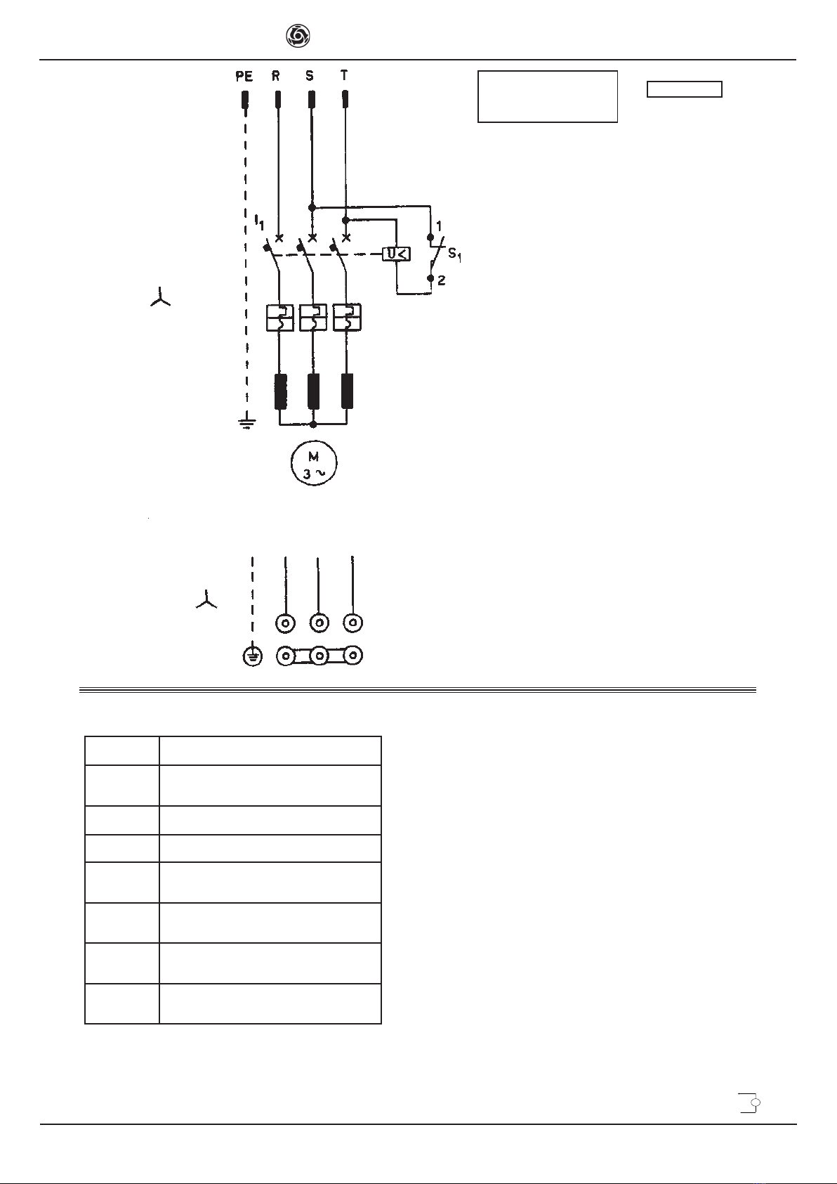
DESCRIPTION
l1 4-6,3 (A) SWITCH + COIL
MMOTOR
S1 LIMIT SWITCH
PE EARTH LINE WIRE
RPHASE LINE
WIRE 1
SPHASE LINE
WIRE 2
TPHASE LINE
WIRE 3
400 V
400 V
PRESA
CEE 400V - 50/60HZ
16A h6
400V / 50-60Hz

IMER INTERNATIONAL S.p.A.
MIX 360
9
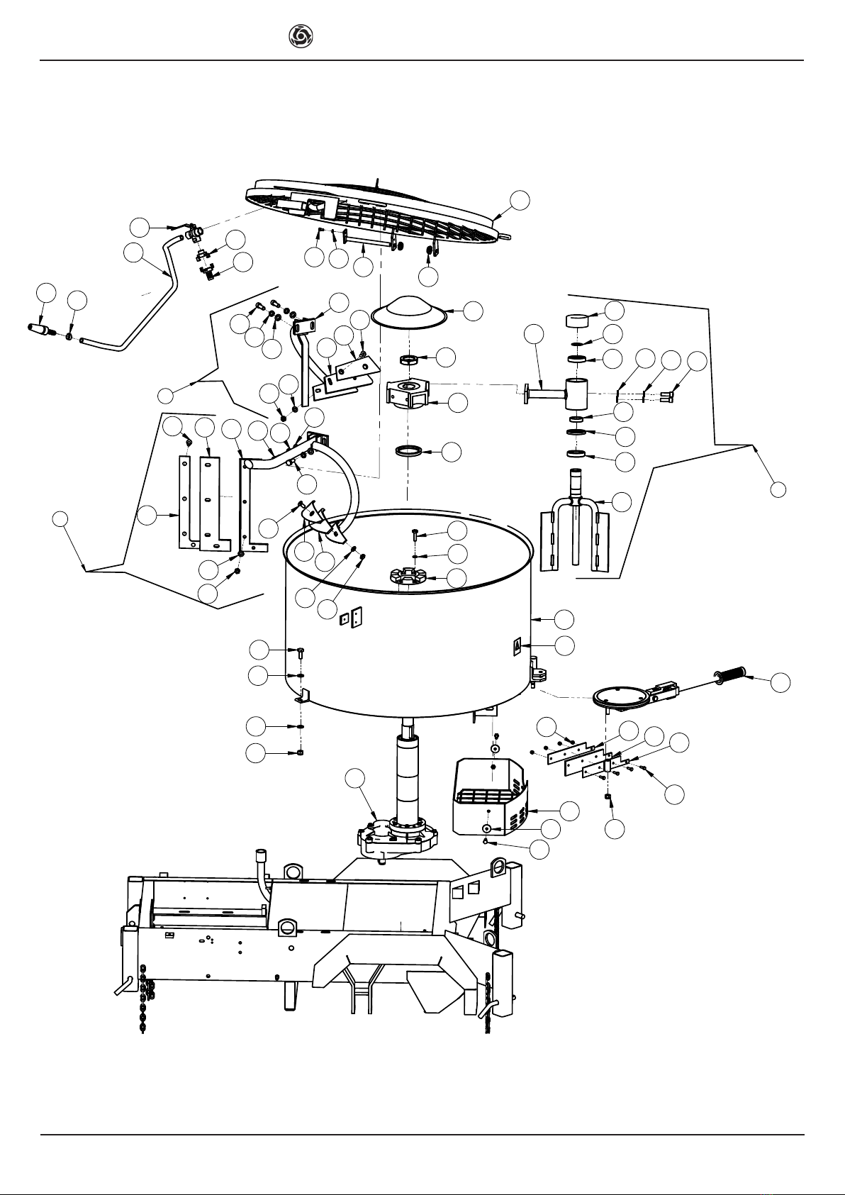
TAV. 1 DESCRIPTION NOTE
Rif. COD.TANK ASSEMBLY
12206763 REDUCTION GEAR
32218068 TAP
42222181 BOLT 5739 M12x30
52222073 BOLT 5739 10X35
62222076 BOLT 5739 M8x25
72223921 NUT Autobl.M12
82224910 WASHER Dev.C72 Ø10z
93224203 FITTING
10 2226800 FITTING
11 3210979 TANK
12 3211274 PROTECTION
13 3211022 ROUND NOZZLE
14 2236593 BOLT PROTECTOR
15 2223924 NUT AUTOBL. M 6
16 3228545 PROTECTION GRID
17 2207750 OIL SEAL RING
18 2222550 BOLT UNI5931 M12x35
19 2224380 WASHER 6593 Ø12X25
20 2224900 WASHER Dev. C72Ø12z
21 2250334 HEAD
22 3211025 ROTATING PADDLE
23 2257710 PROTECTION
24 2252604 PROTECTION
25 2250916 PADDLE ASSEMBLY
26 3211028 PADDLE ASSEMBLY
27 2222599 BOLT 5933 M10X15
28 2223655 NUT 5589 M10
29 3211607 PERIPHERAL S CRAPER
30 2294771 PADDLE
31 2250934 RUBBER
32 2250919 PADDLE HOLDER
33 2294770 PADDLE
34 2250935 RUBBER
35 2227220 STOP RING
36 2204505 BEARING
37 3211026 ARM
38 3206002 MIXER
39 2222016 BOLT 5739 M6X20
40 3211600 OUTLET SCRAPER
41 2247876 RUBBER
42 3211033 BACKING PLATE
43 3211036 RUBBER
44 2253853 BACKING PLATE
45 3211383 BOLT UNI 5739 M6X16
46 2201912 PIN
49 2209953 BUSH
50 2222601 BOLT 5933 M10x30
51 2218069 FIXED NOZZLE
52 2225741 CLIP
53 2226779 HOSE CONNECTOR
54 2292356 RUBBER HOSE
55 3205992 OIL SEAL RING
56 2288205 ADHESIVE LABEL
57 3206003 RING
58 2224920 WASHER M6 Z
59 2223840 NUT
60 2224190 WASHER 8X32 Z
61 2224340 WASHER M10X20 Z
IMER INTERNATIONAL S.p.A.
MIX 360
10
6
4
15
60
39
59
7
19
41
24
40
23
12
44
13
16
57
55
35
36
36
38
19 18
8
5
14
19
7
11
43
28
61
50
42
18 20
19
4
28
61
31
20
18
19
32
34
33
1
21
20
27
28 61
27
49
46
58
45
22
26
25
29
30
37
3
9
10
54
51
17
52
56
TAV. 1
IMER INTERNATIONAL S.p.A.
MIX 360
11
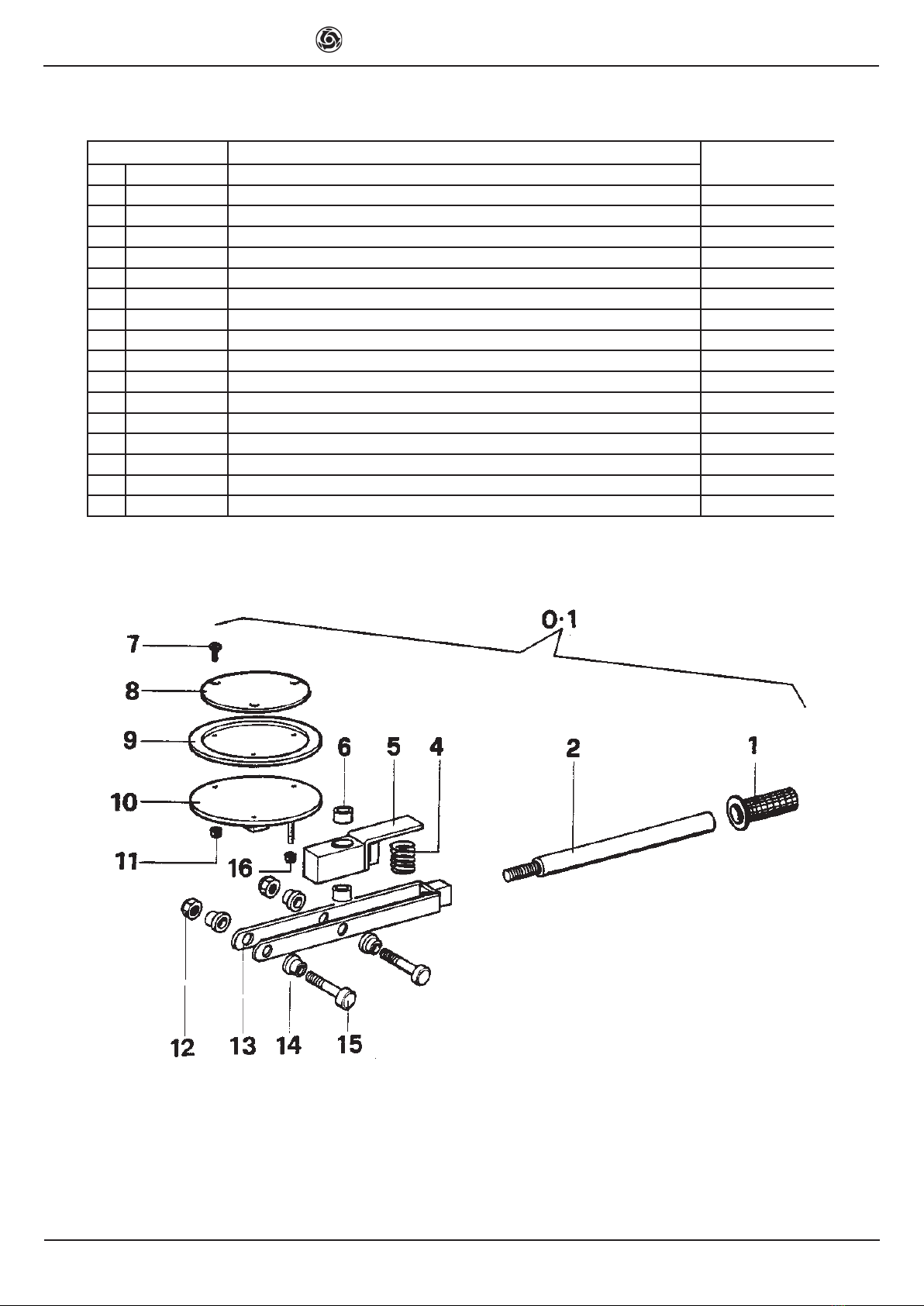
TAV. 2 DESCRIPTION NOTE
RIF. COD.OUTLET ASSEMBLY
0.1 3211022 OUTLET ASSEMBLY
1 2288885 HANDLE
22259894 OUTLET LEVER
4 2231301 SPRING
52237795 JOINT
62209822 BUSH
7 2222600 BOLT 963 M6x26
8 2225033 DISC
9 2292581 GASKET
10 2253863 DISC
11 2223924 NUT
12 2223920 SELF LOCKING NUT AUTOBL. M 6
13 2254015 FORK 7474 M10
14 2209821 BUSH
15 2223006 BOLT
16 2223921 SELF LOCKING NUT 7474 M12
IMER INTERNATIONAL S.p.A.
MIX 360
12
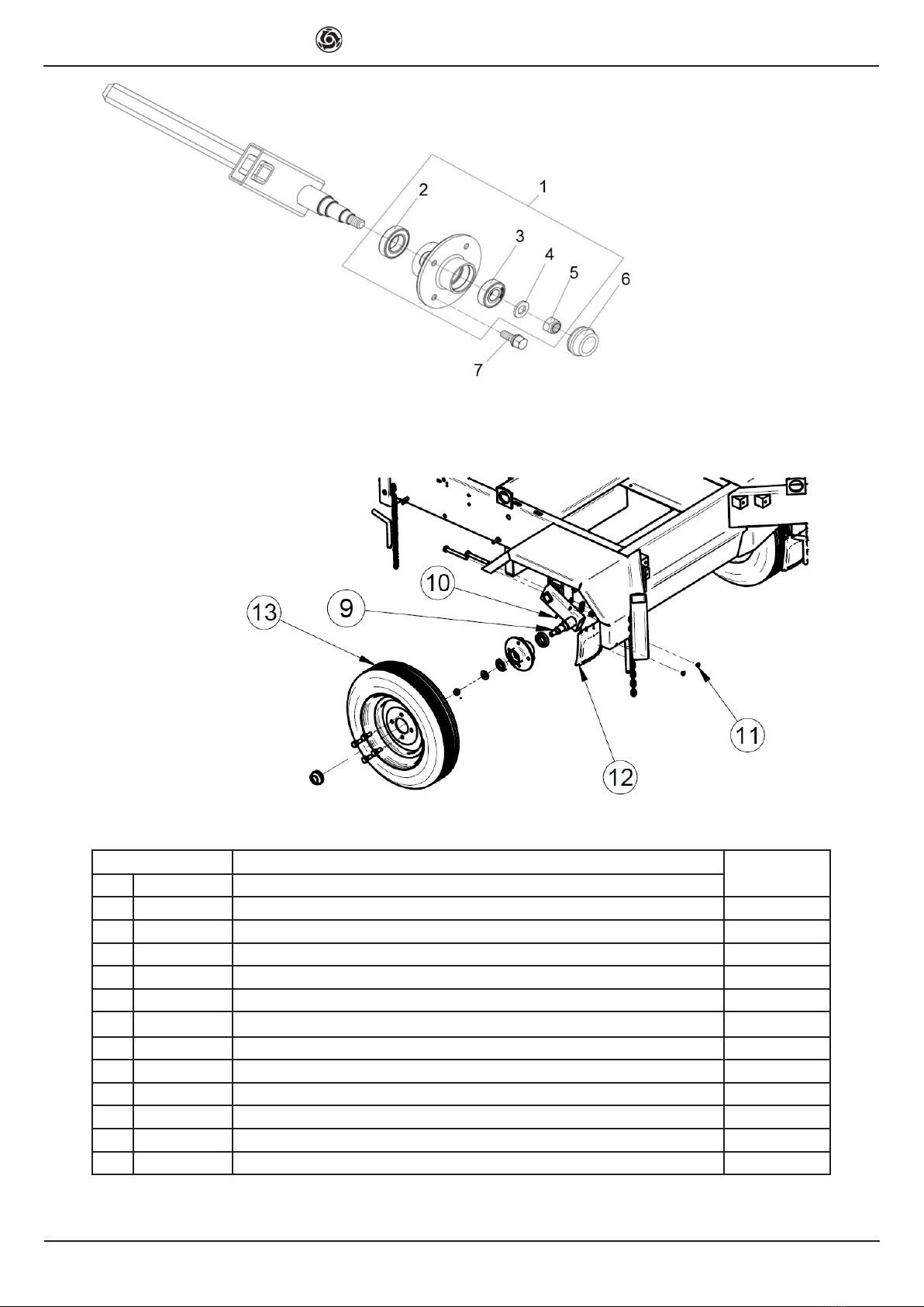
TAV. 3 DESCRIPTION NOTE
RIF. COD.TOWING ASSEMBLY
13236429 HUB
23210629 BEARING
3 2204560 BEARING
4 2224640 WASHER 16x33x3 Z
5 3236427 SELF LOCKING NUT
6 3236428 COVER
7 3234146 BOLT
93236410 AXLE
10 2224532 WASHER 4x8 Z
11 3236412 RIVET
12 3236412 SPLASH GUARD
13 2211407 WHEEL

IMER INTERNATIONAL S.p.A.
MIX 360
13
TAV. 4 DESCRIPTION NOTE
RIF. COD. FRAME ASSEMBLY
1 2222566 BOLT 5931 M12X80
2 2222016 BOLT 6950 M6X20
3 2216277 GASKET
4 2225745 CLIP
52223921 NUT AUTOBL.M10
6 2226700 SPLIT PIN
7 3211268 NIPPLES
8 3225284 SECURITY CABLE
9 3210977 FRAME
10 3201044 PROTECTION
11 3230525 HANDLE/TOW BAR
12 2256128 LEG
13 3210978 JACK
14 3211047 PROTECTION
15 2256600 PIN
16 2257705 TERMINAL
17 3211087 CASING 400v 50 Hz
3211052 CASING Honda - Hatz
18 2224530 WASHER
19 2292370 RUBBER HOSE
21
3211110 IDENTIFICATION PLATE 400v 50Hz
3211106 IDENTIFICATION PLATE Honda
3226905 IDENTIFICATION PLATE Hatz
24 2222530 BOLT
25 2235460 PLUG
26 2222056 SCREW 5739 M 10X25
27 2259537 COVER
28 2224340 WASHER 6592 Ø10X20
29 2223920 SELF LOCKING NUT 7474 M10
30 3230526 HANDLE/TOW BAR MS4-900004
31 3208565 HEAD TOWING
32 2222049 BOLT 5737 12X80 z
33 3209781 TIMONE PLATE
34 3236412 SPLASH GUARD
35 3230304 SUPPORT
36 3208587 PIN
1
32
29
5
6
25
27
10
31 33
13
14
17
30
34
16 24
26 35
36
12
28
8
2
18 2
18
5
3
7
11
15
9
4
19
12
21
IMER INTERNATIONAL S.p.A.
MIX 360
14
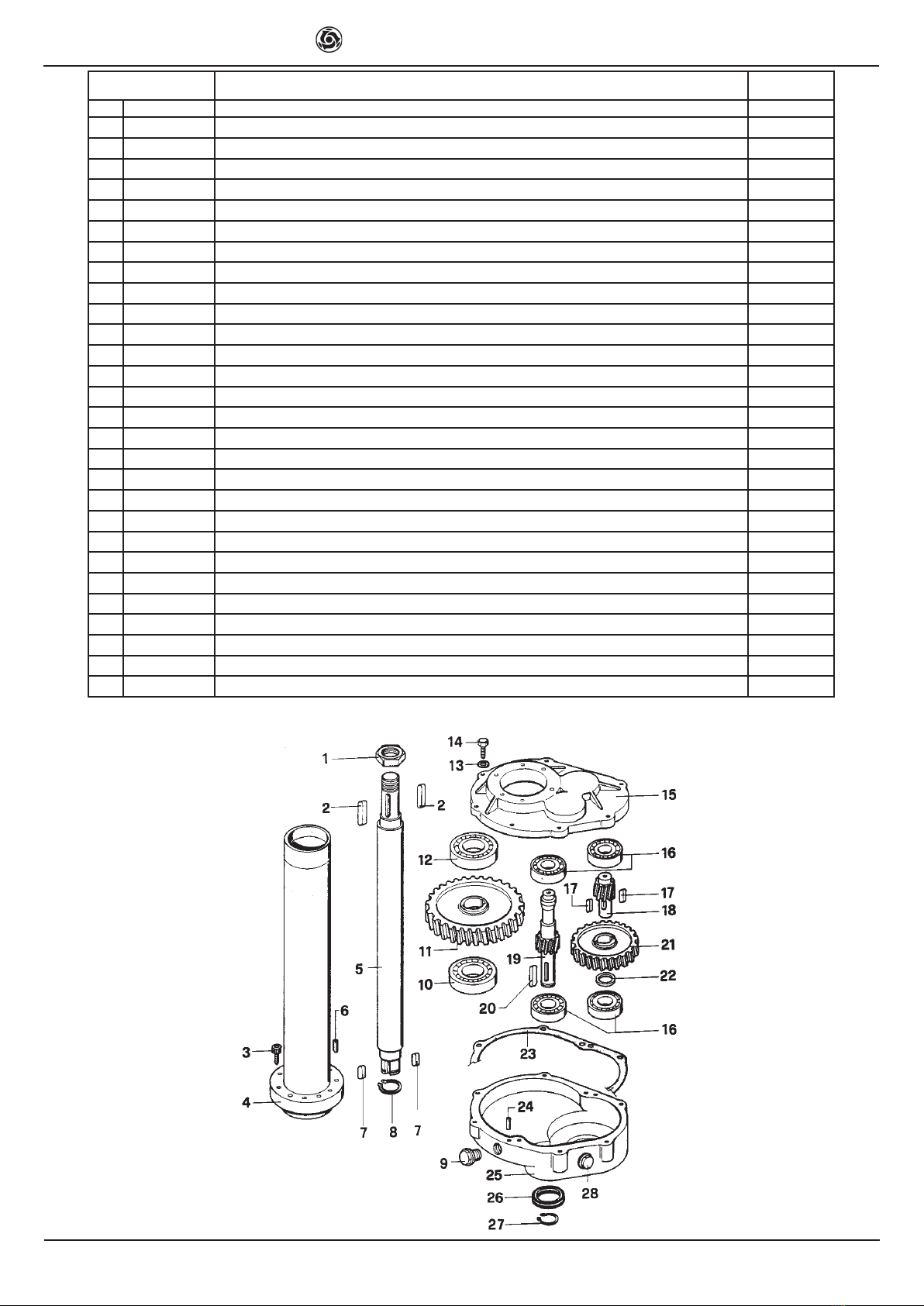
TAV. 5 DESCRIPTION MIX 360
RIF. COD. REDUCTEUR GEAR NOTE
1 2223840 NUT 5589 MB42
22229602 KEY 10X8X50
3 2222530 BOLT 5931 8X35 Z
42258007B ROD
5 2201161 CENTRAL SHAFT
6 2228740 GROUND PIN
72229549 KEY 10X8X30
8 2227260 STOP RING 3653 E34
92235420 OIL LEVEL PLUG
10 2204509 BEARING
11 2202517 GEAR
12 2204510 BEARING
13 2224140 WASHER Ø 8X18
14 2222006 BOLT 5739 M8X30
15 2236735 FLANGE M 21
16 2204550 BEARING 6205
17 2229450 KEY 8X7X20
18 2202858 PINION
19 2202871 PINION
20 2229400 KEY 6604 8X7X30
21 2202526 GEAR
22 2237256 SPACER
23 2216319 GASKET
24 2228820 GUDGEON PIN Ø 6X14
25 2215092 REDUCTION GEAR CASING
26 2207301 OIL SEAL RING 42X25X7
27 2227270 STOP RING 3653 E24
28 3211268 PLUG

IMER INTERNATIONAL S.p.A.
MIX 360
15
TAV. 7 DESCRIPTION NOTE
Rif. COD.ASSEMBLY OF MOTOR 400V 50Hz
2 2222016 BOLT 5739 6x20z
3 3228538 BELT AX 63
4 2205538 PULLEY DP 130 2A
5 2222581 BOLT
63201598 PLUG
8 2224531 WASHER 6593 6x18z
93236670 SWITCH
11 3211047 PROTECTION
12 2222146 SCREW 5739 M10X30
13 2224260 WASHER Ø10X30 z
15 1224113 WASHER 6593 Ø10X50
16 3228506 ELECTRIC MOTOR Kw 3 - 400V/50Hz
17 2205581 PULLEY DP 100 2A
18 2223920 NUT AUT. 7474 M10
19 2223650 NUT uni-5588 M10
20 3211076 BOLT M10x80z
21 3211057 MOTOR MOUNTING PLATE
24 3211073 LIMIT SWITCH
25 3211826 CABLE CLAMP 25X1.5
26 3211096 CABLE CLAMP PG 13.5
27 2222021 BOLT 5739 M6X16z
28 2223920 NUT AUT. 7474 M10
29 3211767 SUPPORT
30 3231562 SPANNER
31 3211067 PIN
32 3211064 SUPPORT
33 3211075 BOLT 7380 M6X40
34 3211091 SUPPORT
35 3211391 SHEATH
36 2222098 SCREW 5739 M10X40
37 3211360 SCREW M.6X10 ISO 7380
38 2222077 SCREW M 10X20 Z
39 2224530 WASHER 6X12.5Z
40 3201044 PROTECTION
41 3228572 CABLE CLAMP
42 3236412 SPLASH GUARD

IMER INTERNATIONAL S.p.A.
MIX 360
16
TAV. 7
12
19 20
4
2
5
40
21
32
31
37
29
16
3
30 24
42
33
39
35
8
27
26
13
13
18
13
34
11
18
13
15
6
25
41
9
25
38
17
36

IMER INTERNATIONAL S.p.A.
MIX 360
17
TAV. 8 DESCRIPTION NOTE
RIF. COD. ASSEMBLY OF MOTOR HONDA - HATZ
12224910 WASHER DEV.C72 Ø10Z
22223920 SELF LOCKING NUT 7474 M10
3 3211077 BOLT 5933 M8X30
5 2284805 HANDLE
62284398 SHEATH AND FERRULE
7 2212120 CABLE ACCELERATOR
8 2224140 WASHER Ø 8X18
92223650 NUT 5588 M10Z
10 3211076 BOLT 5739 M10X80Z
11 3211057 ENGINE MOUNTING PLATE
12 2222088 SCREW 5737 M 8X40
13 2223923 SELF LOCKING NUT M.8
14 3211406 MOTOR HONDA GXV340
3230277 MOTOR HATZ 1B40V 1"
15 2222098 BOLT 5739 M10X40
16 2224260 WASHER 6593 Ø10X30Z
17 2224940 WASHER DEV. Ø8Z C72
18 2221994 BOLT
19 3211428 PULLEY 3A DP=500 F24
20 3211710 BELT A 90
21 3211047 PROTECTION
22 2289357 CLUTCH
24 2221997 SCREW 7/16x70z
25 2222016 BOLT 5739 M6X20z
26 2224530 WASHER Ø6x12.5Z
27 2229327 KEY 4X6.5 UNI 6606
28 3231573 LIMIT SWITCH
29 3211767 SUPPORT
30 3211096 SHEATH GROMMET PG 13.5
31 3211067 PIN
32 2239400 SPRING CATCH
33 3236412 SPLASH GUARD
34 2224531 WASHER 6x18z
36 2237748 SPACER
37 2225796 CLAMP
38 3211075 BOLT 7380 M6X40
39 3211064 SUPPORT
40 2222021 BOLT M6X16z
41 3231562 SPANNER
42 2222581 BOLT
43 3211391 SHEATH

IMER INTERNATIONAL S.p.A.
MIX 360
18
18
12
15 13
8
16
3
24
25
42
2
1
27
36
5
21
11
39
31
38
30
43
14
19
20
41
28
33
40 34
29
26
22
13 37
32
6
7
8
17
10
9
TAV. 8

IMER INTERNATIONAL S.p.A.
MIX 360
19
TAV. 10 DESCRIPTION MIX 360
RIF. COD. LEG EXTENSION KIT (OPTIONAL) NOTE
1 3200457 Leg extension
2 2227048 Key ring
3 2226715 Split pin M 12

IMER INTERNATIONAL S.p.A.
MIX 360
20
221 Westhampton Place
Capitol Heights, MD 20743
Ph. 301.336.3700
Fax 301.336.6687
Toll Free: 800.275.5463
www.imerusa.com
We warrant to the original purchaser that the IMER equipment described herein (the "equipment")
shall be free from defects in material and workmanship under normal use and service for which it was
intended for period of one (1) year from the date of purchase by the original purchaser.
Our obligation under this warranty is expressly limited to replacing or repairing, free of charge, F.
O.B. our designated service facility, such part of the equipment as our inspection shall disclose to be
defective. Parts such as engines, motors, pumps, valves, electric motors, etc. furnished by us, but
not manufactured by us, will carry only the warranty of the manufacturer. Transportation charges or
duties shall be borne by purchaser. This shall be the limit of our liability with respect to the quality of
the equipment.
This warranty shall not apply to any equipment, or parts thereof, which has been damaged by rea-
son of accident, negligence, unreasonable use, faulty repairs, or which has not been maintained and
operated in accordance with our printed instructions for the equipment. Further, this warranty is void if
the equipment, or any of its components, is altered or modied in any way.
THIS WARRANTY IS EXPRESSLY IN LIEU OF ALL OTHER WARRANTIES, EXPRESSED OR
IMPLIED, INCLUDING ANY IMPLIED WARRANTY OF MERCHANTABILITY OR FITNESS FOR A
PARTICULAR PURPOSE.
We make no other warranty, representation or guarantee, nor is anyone authorized to make one on
our behalf. We shall not be liable for consequential damage of any kind, including loss or damage
resulting, directly or indirectly, from the use or loss of use of the machine. Without limiting the gene-
rality of the foregoing, this exclusion from liability embraces the purchaser's expenses for downtime,
damages for which the purchaser may be liable to other person, damages to property, and injury or
death of any persons.
This warranty shall not be deemed to cover ma ntenance parts, including but not limited to blades,
belts, hoses, hydraulic oil, or lters, for which we shall have no responsability or liability whatsoever.
ONE YEAR WARRANTY
Table of contents
Other IMER USA Mixer manuals


