IMER COMBI 250 VA Guide

2006/04
- Cod. 3226142 -
IMER INTERNATIONAL S.p.A.
53036 POGGIBONSI (SIENA) loc. SALCETO
(ITALY)
tel.0577 97341 - fax 0577 983304
SEGATRICE
SCIE
SAWING MACHINE
SÄGEMASCHINE
TRONZADORA
INTERNATIONAL S.p.A
COMBI 250 VA
1188160 (230V-50Hz) / 1188162 (110V-50Hz)
I
manuale uso manutenzione ricambi
F
manuel utilisation entretien pieces de rechange
GB
Operating,maintenance, spare parts manual
D
Handbuch für Bedienung, Wartung und Esatzteile
E
manual de uso, mantenimiento y recambios

IMER INTERNATIONAL S.p.A.
COMBI 250 VA
10
Dear Customer,
Congratulations on your choice of purchase: IMER saws are
the result of years of experience and are equipped with all the
latesttechnicalinnovations.
- WORKING IN SAFETY.
To work in complete safety, read the following instructions
carefully before using the machine.
To work in complete safety, read the following instructions
carefully before using the machine.
This OPERATION AND MAINTENANCE manual must be kept on
site by the person in charge, e.g. the SITE FOREMAN, and
must always be available for consultation.
The manual is to be considered integral part of the machine
and must be kept for future reference (EN 12100/2) until the
machine is disposed of. If the manual is damaged or lost, a
replacement may be requested from the manufacturer.
The manual contains important information regarding site
preparation, machine use, maintenance procedures, and
requests for spare parts.
Nevertheless, the installer and the operator must both have
adequate experience and knowledge of the machine prior to
use.
To guarantee complete safety of the operator, safe operation
and long life of equipment, follow the instructions in this
manual carefully, and observe all safety standards currently in
force for the prevention of accidents at work (use of safety
footwear and suitable clothing, helmets, gloves, goggles etc.).
- Make sure that all signs are legible.
- It is strictly forbidden to carry out any form of
modification to the steel structure or working parts of
the machine.
IMER INTERNATIONAL declines all responsibility for failure to
comply with laws and standards governing the use of this
equipment, in particular; improper use, defective power
supply, lack of maintenance, unauthorised modifications, and
partial or total failure to observe the instructions contained in
this manual.
IMER INTERNATIONAL reserves the right to modify features of
the saw and contents of this manual, without the obligation to
update previous machines and/or manuals.
1. TECHNICAL DATA
Technical data are stated in table 1 and electrical
specifications in table 2.
TECHNICAL DATA - Table 1
Model
COMBI 250 VA
Max. blade diameter
250 mm
Diamond Blade hole diameter
25.4 mm
Single phase 230 V 50 Hzmotor power
Single phase 110 V 50 Hzmotor power
1.1 kW
1.1 kW
Max. blade rotationspeed (230 V 50 HZ)
Max. blade rotationspeed (110 V 50 HZ)
2800 rpm
2800 rpm
Cutting table dimensions
850x500 mm
Lengthof 90° cuts (thickness=16mm)
Length of cuts from above
660 mm
785 mm
Maximum cut depthwithsingle stroke
Maximum cut depthwithtwo stroke
66 mm
105 mm
Water pump flow rate
13 l/min
Water tank capacity
36 L
Machine dimensions
1050x565x480
Packed machine dimensions
1090x610x525 mm
Weight withpackaging
43 kg
Feature European motor
(230V/50Hz) European motor
(110V/50Hz)
Power (kW) 1.1 1.1
Rated voltage (V) 230 110
Frequency (Hz) 50 50
Absorbed current 7.8 15.4
Number of poles 2 2
rpm 2800 2800
Service type S6 40% S6 40%
Insulation category F F
Protection category IP55 IP55
Capacitor (µF) 25(Ø 40x92) 90(Ø 50x120)
2. DESIGN STANDARDS
COMBI 250 saws have been designed and manufactured
according to the following standards: EN 12100-1-2; EN
60204-1;EN 12418.
3.
SOUND PRESSURE LEVEL AND VIBRATIONS
Table 3 shows the sound pressure level measured loadless at
the operator s ear (LPA) and of the vibrations transmitted during
operation.
TABLE 3
SAWING MACHINE
TYPE OF MOTOR
LpA
Aeq
Combi 250 VA
ELECTRIC
86 dB
2.57 m/s
2
4. GENERAL SAW DESCRIPTION
4.1
General description:
The Combi 250 VA is a saw comprising the following main
sub-groups :
- cutting head (ref. A fig.1).
- sliding guide (ref. B fig.1).
- water collection tank (ref. C fig.1).
- cutting surface (ref. F fig.2).
- stand (ref. G fig.5).
- power cable.
The cutting head is mounted on a reinforced aluminium profile
and is equipped with horizontal and vertical movement
facilities. The aluminium profile is hinged onto die-cast arms
(ref.H fig. 5) and the entire unit can rotate through 45° ( fig. 6)
by means of the relative handwheels (ref.L fig. 7).
The cutting surfaces are positioned on the tubular frame of the
saw which is placed on the tank constructed in impact-
resistant plastic.
The water immersion pump is mounted below the cutting
surfaces on a special bracket and supplies a water distributor
inside the blade guard for cooling the cutting blade during
operation.
The high resistance plastic handle (ref.M fig. 6), is equipped
with the main ON-OFF switch on the operator side to facilitate
saw activation and shutdown.The raised position of the red
OFF button on the handle is designed to facilitate shutdown of
the machine in the event of an emergency. The motor
capacitor is located in a protected position inside the handle.
The saw is fitted with a guard to guarantee optimal safety
during operation and to protect the user during cutting cycles.
A valve is mounted above the blade guard to adjust the flow
rate of water delivered to the cutting blade.
4.2 Processable materials:
This saw has been designed for cutting the following
materials: ceramic tiles, masonry and stone in general with
maximum dimensions compatible with the length, cutting depth
and dimensions of the surfaces specified in Table 1.
Maximum weight of processable materials: 25 kg.
GB

IMER INTERNATIONAL S.p.A.
COMBI 250 VA
11
4.3
Unsuitable material
:
Materials unsuitable for this machine are all those not specified
in paragraph 4.2.
In any event, before using the saw with materials other than
as specified by the manufacturer for this saw model, contact
IMER INTERNATIONAL S.p.A.
-
Use of this machine with workpieces outside the
specified dimensions is strictly prohibited and constitutes
a hazard for the operator.
5.
OPERATION SAFETY
- Before using the saw, ensure that all protection
devices are fitted.
- Never use the saw in environments subject to the
risk of explosions, fire or underground.
The saw is not fitted with specific lighting and therefore the
workplace must be sufficiently lit for this purpose.
The power lines must be laid to prevent any possible damage.
Never stand the saw on the power supply cable.
Ensure that the electrical connection is protected against the
risk of water penetration in connectors. Use exclusively
connectors and couplings equipped with water spray
protection.
- Never use inadequate or makeshift electrical lines or cables
without earthing; if in doubt consult a specialised technician.
- Repairs to the electrical circuit must be performed
exclusively by specialised personnel. Disconnect the machine
from the power supply before performing maintenance or
repairs.
6.
GENERAL SAFETY WARNINGS
Note that this machine has been designed to ensure optimal
performance and maximum safety: however the operator must
also guarantee this level of safety by paying special attention
to the machine throughout all work phases.
1.
Ensure that an efficient earthing system is
installed.
2.
Work only with all protection devices fitted
correctly and in efficient working order.
3.
Keep the machine clean: general cleaning
(and the work surfaces in particular) represents an
important safety factor.
4.
Always stop the machine and disconnect from
the power supply before cleaning or removing any
protection device (for maintenance or disassembly
purposes).
If water jets are used for cleaning, never point jets
directly at the power supply unit or electric motor.
5.
Remove rings, watches, bracelets or ties before
using the machine; these elements constitute a serious
hazard to the operator.
Also ensure that sleeves are tight around the wrists,
hair is tied back and robust footwear is used.
6.
Never cut workpieces that have dimensions or
weight that are not suited to machine i capacity as
specified by the manufacturer (see point 4.2)
7.
Always use personal protection devices such
as safety goggles, suitably sized gloves, ear muffs or
plugs and hair caps when necessary.
8.
Use original diamond blades as recommended
by the manufacturer to ensure optimal performance of
the machine.
9.
Always keep hands well away from the working
zone while the machine is running; before removing
workpieces from the blade area, always press the stop
pushbutton to shut down rotation.
10.
The instructions in this manual are aimed at
machine users (operators, maintenance engineers).
11.
Never use diamond blades that are chipped or
deformed.
12.
Never use blades over the rotation speed
specified by the manufacturer.
13.
Use exclusively water-cooled continuous rim
blades suited to the material to be cut.
14.
Never dry cut material or cut when cooling
water levels are low.
15.
Ensure that the machine, with or without stand,
is placed on a stable surface with a maximum
inclination of 5°.
7.
SAFETY DEVICES
The COMBI 250 VA has been constructed taking into account
current harmonised European safety standards.
According to machine directive 98/37/EEC all safety devices
have been installed with the aim of safeguarding the operator.
7.1 Guards and safety devices
The machine is equipped with fixed guards, secured by
means of screws and protections that prevent access to
moving or dangerous parts.
All fixed guards, covers, shields fixed by means of screws
have been envisaged to protect the operator (maintenance
engineers, technicians and others) from possible accidents
cause by electrical discharge or moving mechanical parts.
Therefore use of the machine with guards removed or
modified in any way is strictly prohibited.
- Before performing maintenance or repairs to the
machine, turn it off via the main switch and disconnect
from the power supply to prevent inadvertent start-up
and isolate all machine electrical circuits.
8. MACHINE INSTALLATION
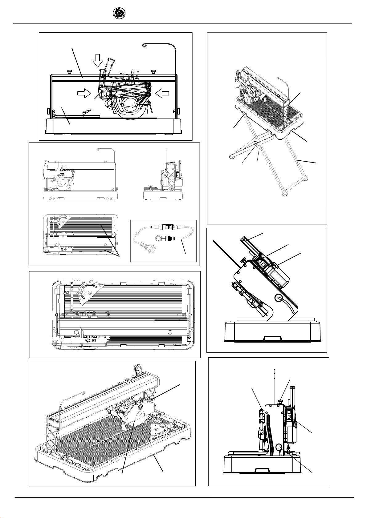
8.1 Lifting and handling
The Combi 250 VA saw weights 38 Kg and can be moved by
means of the side handles on the tank (ref.N fig.5).
- Always empty the tank before moving the machine.
8.2 Positioning
The machine must be placed on a smooth surface that is at
least as large as the tank, with the saw on the relative stand.
- Ensure that the stand is positioned on the relative
inserts on the tank base and thus secured.
The correct side for the operator is as shown in Fig.3 position X.
In the event of moving the saw, take care to secure the head
by means of the fixing knobs (ref.O, L fig.7) and carry the
machine by means of the handles on the tank (ref.N fig.5)
after disconnecting the power supply.
- Always remove the plug from the mains power before
moving the machine.
8.3 Stand assembly
The stand is supplied disassembled. Firstly, join the two parts
of each leg making sure that the inner and outer holes are
aligned. Join the two legs fitting the safety catches (ref. U fig.
5), tighten the screws and self-locking nuts with the spanner
provided (ref. T fig.5) taking care to allow rotation of the legs.
8.4 Side roller assembling (optional kit p/n1188086)
The side roller table is supplied with side supports already assembled.
First of all its necessary to fit such supports
inside the proper seats housed alongside the saw up to the stop. Now
lower the side roller table up its levelled to the saws table (fig. 8).
To fit the central support its necessary to reverse the screw fitting
side of the stand which is aside the side roller table.
Then place the support, fitting it inside the screw and tighten it so to
hold the table. Then tighten the nut.
GB

IMER INTERNATIONAL S.p.A.
COMBI 250 VA
12
9.
ELECTRICAL CONNECTION
- Ensure that voltage corresponds to machine
dataplate specifications
.
The power supply line must be equipped with current overload
protection (e.g. thermal cutout) and protection against indirect
contact (e.g. residual current circuit breaker).
Connect the machine to an efficient earthing system.
The size of the power cable wires must be based on
operating current and length of the power line to prevent
excessive voltage drops (ref.Table 4).
Combi 200 VA - Tab. 4
Lunghezza cavo (m)
Longueur câble (m)
Cable length (m)
Kabel Länge (m)
Longitud cable (m)
V 230
I= 5.8 A 0 ÷ 22 23 ÷ 36 37 ÷ 58
V110
I= - A - - -
sezione cavo (mm²)
section câble (mm²)
cable (mm²)
kabel (mm²)
cable (mm²)
1.5 2.5 4
Connect the saw plug to the mains and tighten the mechanical
retainer ring with IP67 protection rating.
- The saw is now ready for operation.
11.
SAW START-UP
Connect the mains power cable to the plug on the electrical
panel.
RESIDUAL CURRENT CIRCUIT PROTECTION (KIT 230V-P/
N.1169245 - KIT 110V-P/N.1169249):
It is compulsory to power the sawing machine using a differential
switch (230 V; current intensity 30 mA; max. cut-in time 20
sec).
KIT code 1169245 can be supplied (ref. E fig. 2) to be connected on the
supply cable as shown in the diagram (page 13).
When the KIT has been installed, press the green ON button to be able
to start the sawing machine. An orange led will light up (differential
protection on).
RESIDUAL CURRENT CIRCUIT BREAKER TEST:
Press the black key TEST on the RCCB; the switch
disconnects and the orange led turns off.
After performing the TEST, press the ON key again to activate
the RCCB.
-Carry out the RCCB TEST before each machine
start-up.
Then start the saw by means of the switch on the handle (ref.
P fig.6) , comprising two buttons: green for start, red for stop.
The switch is fitted with low voltage protection; in the event of
accidental power failure, press the green button again to
resume operation.
In the event of an emergency, press the red pushbutton to
shut down the machine and disconnect the plug from the
power mains.
The RCCB is deactivated each time the power supply is
disconnected.
THERMAL CUTOUT PROTECTION:
- The electric motor is protected against overload by
a thermal cutout; in the event of overheating this device
shuts down the motor.
Cool the motor and restart by means of the RCCB
switch and the main switch on the handle (ref.P fig. 6).
The machine is protected against short circuits by a
magnetic protection inside the RCCB.
12 . MACHINE USE
Operation
The correct side for the operator is shown in fig. 3 ref X.
Fill the water tank to the maximum level (approx. 42 litres).
Connect the machine to the power mains and start as
described in paragraph 11.
Open the valve (ref.V fig.7) and ensure sufficient flow of
cooling water to the diamond blade.
Cutting
Place the material to be cut on the cutting surface against the
fence at the required angle using a goniometer.
Adjust the height of the cutting head by means of the
handwheel (ref. R fig. 6).
Ensure that the handwheels for angled cuts (ref. L fig. 7) and
tightened fully down.
Start the saw as described in paragraph 11.
Proceed with cutting moving the saw head by means of the
handle.
In the event of blade rotation shutdown due to excessive
force, free the disk by moving it forwards and wait for the
saw to reach normal operating speed before resuming
operation.
Angled cuts
Loosen the handwheels (ref.L fig. 7), set the cutting head at
the required angle, retighten the handwheels, and proceed as
described in the point above.
Ensure that the tank is kept full during all work phases and in
the event of prolonged work intervals replace water regularly
and remove all processing residue.
Press the workpiece by hand onto the cutting surface.
Apply sufficient pressure on the handle to move the cutting
head without blocking the blade.
13. MAINTENANCE
13.1 Premise
Routine maintenance operations can also be performed by
non-specialised personnel provided that all safety standards
specified in the relative sections of this manual are observed
at all times.
13.2 Machine cleaning
The machine should be cleaned
exclusively
when it is
stationary.
- All power switches must be set to 0 and plugs
must be disconnected from the mains.
Never use compressed air; this could cause infiltration of dust
or residue in enclosed parts
.
Ensure that the cooling water nozzles are not obstructed
.
Above all the cooling water in the tank must be changed every
day
.
Do not use detergents or lubricants.
13.3
Waste disposal
As regards disposal of processing waste observe all current
legislation in the country of use.
13.4 Repairs
Repairs to the electrical installation must be performed
exclusively by specialised personnel. Use exclusively original
IMER spare parts; modifications to parts are strictly prohibited.
The special design of the COMBI 200 VA ensures that no other
maintenance other than as specified above is required.
Ensure that the contacts of the power plug and plug-switch
assembly are efficient. If oxidation is detected, clean
immediately
- In the event of activation of the RCCB, check the
machine and arrange for repairs if necessary exclusively
by specialised personnel
.
13.5
Cleaning the tank
Clean the tank in the event of build-up of sediment on the
base, or at least once a day. Failure to clean the tank could
impair operation of the immersion pump used for circulation of
the diamond blade cooling water.
GB

IMER INTERNATIONAL S.p.A.
COMBI 250 VA
13
To clean the tank, disassemble from the machine, lock the
head, hold it by the arms and rinse with a direct water jet (this
is to avoid direct contact of the water with electrical parts),
the proceed with manual cleaning using cloths or brushes.
Take care not to damage cables when replacing the machine
on the tank
Take care not to damage the pump when placing the machine
on the surface
13.6 Blade replacement
The diamond blade is made of material that may be damaged
when subject to high temperatures, and therefore must be
cooled during the work phases.
To replace the blade, proceed as follows:
1.Block axial movement of the cutting head by means of the
handwheels (ref. O fig. 7).
2. Disassemble the front guard (ref.D fig.4).
3. Loosen the locknut by rotating clockwise (left thread), using
a 19 mm wrench.
4. Move the cutting head forward slightly and incline to remove
the blade from its seat.
5 . Ensure that there are no foreign objects between the fixing
flange and diamond blade. During disassembly, avoid use of
tools that could dent or deform the flange.
6 . Insert the new blade proceeding in reverse order of the
operation described at point 4. Take special care to ensure
correct direction of rotation of the diamond blade.
7. Tighten the blade locknut fully down by rotating
anticlockwise (left thread), to a torque of 40 Nm.
13.7 Cleaning the cooling water supply circuit
At regular intervals (or when the flow rate of the blade cooling
water is reduced) clean the cooling water supply circuit. To do
this, disassemble the delivery nozzle (ref. S fig. 4) located
inside the blade guard and clean in water.
Periodically clean the cooling water delivery line between the
pump and valve, (ref.V fig. 7) and blade guard using water.
Problem Cause Remedy
Start button is
pressed but
motor does not
start.
- No voltageon
power line.
- Socket and plug
not fitted correctly.
- RCCB switch not
activated
- Power cable from
plug to panel is
disconnected.
- Electric wireloose
inside motor
terminal board.
- Electric wireloose
inside panel.
- Start switch
faulty.
- Check power line.
- Fit correctly.
- Activate RCCB
ON button.
- Replacecable
- Arrangerepairs
by electrician
- Arrangerepairs
by electrician.
- Changeswitch.
No delivery of
cooling water
to blade.
Bladedoes not
cut. - Incorrect
direction of blade
rotation.
- Bladeworn.
- Disassemble
blade and
reposition in the
direction as shown
on theblade label.
- Fit new blade.
- Refer to machinecleaning
tank cleaning .
GB
14. TROUBLESHOOTING
- CAUTION!!! All maintenance operations must be
performed exclusively with the machine switched off ,
with the selector set to 0 and the power plug
disconnected from the mains.
S1
Control switch
C1
Capacitor
PE
Earthing cable
N
Neutral line cable
L1
Phase line conductor
M1
Blade motor
M2
Pump motor
Id
Current circuit breaker
RESIDUAL CURRENT
CIRCUIT PROTECTION
KIT 230V-COD.1169245
KIT 110V-COD.1169249:

IMER INTERNATIONAL S.p.A.
COMBI 250 VA
22
Fig. 7
O
V
Fig. 1
Fig.3
P
Fig. 4
DC
Fig. 6
R
P
Fig. 5
N
H
G
B
A
C
X
F
M
N
TU
V
Fig. 2
0
T
E
S
T
O
N
I
K
O
P
P
P
R
C
D
-
2
p
o
l
I
n
1
6
A
U
n
2
3
0
V
A
C
I
n
3
0
m
A
I
P
5
5
C
E
a
r
t
.
n
r
.
1
9
3
2
-
2
5
T
U
V
D
E
E

IMER INTERNATIONAL S.p.A.
COMBI 250 VA
23
(I)
7. RICAMBI
:Per tutti gli ordini dei pezzi di ricambio vogliate indicare: 1 - Tipo di macchina. 2 - Numero di codice e di riferimento collocato in corrispondenza di ogni definizione. 3
- Numero di serie e anno di costruzione riportato sulla targhetta della macchina.
SIMBOLOGIA
: Intercambiabilità (esempio): Fino alla macchina matricola N° 5240 è stato installato il rif.1
cod.3204530,dalla mcchina matricola N° 5241 è stato installato il rif.1.1 cod.3204520. Il rif.1.1 è intercambiabile (
) con il rif.1. Non sono intercambiabili i rif.1 e rif.1.1 se in tabella è presente il
simbolo (
)
.
(F)
7. PIECES DE RECHANGE
:Pour toutes les commandes de pièces de rechange, veuillez indiquer: 1 - Le Type de machine 2 - Le Numéro de code et de référence se trouvant en face
de chaque définition 3 - Le Numéro de série et l'année de construction se trouvant sur la plaquette d'identification de la machine
SYMBOLOGIE
: Intercambiabilità (exemple):Jusqu'à la machine matricule N° 5240, nous avons installé la réf. 1 code 3204530; à partir de la machine matricule N° 5241, nous avons installé la réf.
1.1 code 3204520. La réf. 1.1 est interchangeable (
) avec la réf.1. Les réf. 1 et réf. 1.1 ne sont pas interchangebles si le symbole (
) n'est pas sur le tableau.
(GB)
7. SPARE PARTS
:All orders for spare parts must indicate the following: 1 - Type of machine.2 - Part number and position number of each part.3 - Serial number and year of manufacture
reported on the machine's identification plate.
SYMBOL
: Interchangeability (example):Pos..1 P.n. 3204530 was installed on machincs up to N° 5240 and Pos.1.1 P.n. 3204520 installed on machine N° 5241 onwards. Pos. 1.1 is interchangeable
(
) with Pos. 1.Pos. 1 and Pos. 1.1 are not interchangeable if the (
) symbol appears in the table.
(D)
7. ERSATZTEILE
: Für Ersatzteilbestellungen bitte die folgenden Angaben machen: 1) Maschinentyp 2) Jeweils zugeordnete Art.-Nr. und Positionsnummer 3) Seriennummer und
Baujahr (Angabe auf dem Maschinenschild)
SYMBOLE
: Austauschbarkeit (Beispiel):Bis zur Maschinenummer 5240 ist Ref. 1 Cod. 3204530 und ab Maschinennummer 5241 ist Ref. 1.1 Cod. 3204520 installiert worden. Ref. 1.1 und Ref. 1 sind
austaschbar (
). Ref. 1 und Ref.1.1 sind nicht austauschbar, wenn das Symbol (
) angegeben ist.
(E)
7. PIEZAS DE RECAMBIO
:Para pedir una pieza de recambio hay que indicar siempre: 1 -El tipo de máquina. 2 -Los números de gódigo y de referencia indicados en correspondencia
de cada definición. 3 -El número de serie y el año de construcción indicados en la placa de la máquina.
SIMBOLOGIA
: Intercambiabilidad (ejemplo): Hasta el equipo con matrìcula N° 5240, se ha instalado la pieza con ref. 1 y còd. 3204530; a partir de la màquina con matrìcula N° 5241, se ha instalado
la pieza con ref. 1.1 y còd. 3204520. La pieza con ref. 1.1 se puede intercambiar (
) con la pieza con ref. 1. Si en tabla se halla presente el sìmbolo (
), las piezas co referencia 1 y 1.1 no son
intercabiables.
TAV. 1 STRUTTURA MACCHINA - STRUCTURE MACHINE - MACHINE STRUCTURE - MASCHINENAUFBAU - ESTRUCTURA DE LA MAQUINA
Rif. Cod. I F GB D E Note
1 3210055 VASCA CUVE TANK BECKEN RECIPIENTE
2 2222449 VITE VIS SCREW SCHRAUBE TORNILLO 6954 3,5X19
3 2235428 TAPPO BOUCHON CAP STOPFEN TAPÓN
4 3210576 RONDELLA RONDELLE WASHER UNTERLEGSCHEIBE ARANDELA
6 2284866 POMELLO POIGNEE KNOB KNOPS POMO
7 3223318 VITE VIS BOLT SCHRAUBE TORNILLO 8X30
8 2223920 DADO ECROU NUT MUTTER TUERCA AUTOBL. M10
9 3226087 RONDELLA RONDELLE WASHER UNTERLEGSCHEIBE ARANDELA
11
3211381 POMELLO POIGNEE KNOB KNOPS POMO
12 3226076 SUPPORTO
GONIOMETRO SUPPORT
GONIOMÈTRE GONIOMETER
SUPPORT WINKELMESSER-HALT-
ERUNG SOPORTE DEL
GONIÓMETRO
13 3226078 GONIOMETRO GONIOMÈTRE GONIOMETER WINKELMESSER GONIÓMETRO
14 3223279 POMELLO POIGNEE KNOB KNOPS POMO
16 2222189 VITE VIS BOLT SCHRAUBE TORNILLO 5737 8X45
17 3226265 PIANO SX PLATEAU GAUCHE L.H. SURFACE LINKE ARBEITSFLÄCHE SUPERFICIE IZQ.
18 3226064 PIANO DX PLATEAU DROIT R.H. SURFACE RECHTE
ARBEITSFLÄCHE SUPERFICIE DCHA.
19 2222776 VITE VIS BOLT SCHRAUBE TORNILLO 5739 6X16
20 3210087 MOLLA RESSORT SPRING FEDER MUELLE
21 3226357 BRACCIO ANTERIORE BRAS AVANT FRONT ARM VORDERER ARM BRAZO ANTERIOR
22 2223280 DADO ECROU NUT MUTTER TUERCA
23 3210099 VITE VIS BOLT SCHRAUBE TORNILLO
24 3226073 BATTUTA DESTRA BUTÉE DROITE RIGHT FENCE RECHTER ANSCHLAG TOPE DERECHO
25 2222541 VITE VIS SCREW SCHRAUBE TORNILLO 5931 6X25
26 3210070 ASTA TIGE ROD STAB VARILLA
27 3210071 SUPPORTO SUPPORT SUPPORT UNTERLAGE SOPORTE
28 3226358 GONIOMETRO
COMPLETO GONIOMÈTRE
COMPLETE GONIOMETER
ASSEMBLY KOMPLETTES
WINKELMESSER GONIÓMETRO
COMPLETO
30 3204865 POMELLO POIGNEE KNOB KNOPS POMO
31 3210069 ADESIVO BATTUTA ADHSIF BUTEE FENCE ADHESUVE
LABEL SCHILD ANSCHLAG ADHESIVO TOPR
32 3210068 GUIDA SCORRIMENTO COULISSE SLIDEWAY GLEITFÜHRUNG GUÍA DE
DESLIZAMIENTO
33 3226359 BRACCIO POSTERIORE BRAS ARRIÈRE REAR ARM HINTERER ARM BRAZO POSTERIOR
34 3226074 BATTUTA SINISTRA BUTÉE GAUCHE LEFT FENCE LINKER ANSCHLAG TOPE IZQUIERDO
35 3226360 ASTA GONIOMETRO TIGE GONIOMÈTRE GONIOMETER ROD WINKELMESSERS
STANGE GONIOMETRO
36 3226069 FIANCATA ANTERIORE CÔTÉ ANTÉRIEUR FRONT SIDE VORDERE SEITE PANEL DELANTERO
37 3226070 FIANCATA
POSTERIORE CÔTÉ POSTÉRIEUR REAR SIDE HINTERE SEITE PANEL TRASERO
Rif.
Cod. I F
GB
D E Note
1 3204530
Riduttore
Réducteur
Reducer
Untersetzungsgetriebe
Reductor 5240
2 3204520
Riduttore
Réducteur
Reducer
Untersetzungsgetriebe
Reductor 5241

IMER INTERNATIONAL S.p.A.
COMBI 250 VA
24
17
18
20
23
26
31
32
33
24
34
21
28
8-9
4-5-6-7
1
2
3
19
27
30
22
25
4
11
12
13
14
16
35
36
37

IMER INTERNATIONAL S.p.A.
COMBI 250 VA
25
TAV. 2 MONTAGGIO MOTORE- MONTAGE MOTEUR - ASSEMBLY OF MOTOR - MONTAGE MOTOR - MONTAJE MOTOR
RIF.
Cod.
I F
GB
D E
Note
2
3210043
DISTANZIALE
ENTRETOISE
SPACER BRACKET
DISTANZHULSE
ESPACIADOR
3
3201339
VITE
VIS
BOLT
SCHRAUBE
TORNILLO
5933 M8x25
4
3210044
FLANGIA INTERNA FLASQUE INTERIEURE INNER FLANGE FLANSCH INN. BRIDA INTERIOR
6
3210046
FLANGIA ESTERNA FLASQUE EXTERIEURE OUTER FLANGE FLANSCH AUSS. BRIDA EXTERIOR
7
3210053
DADO
ECROU
NUT
MUTTER
TUERCA
M12 SX
8
3211936
3211938
MOTORE
MOTEUR
MOTOR MOTOR MOTOR
230V
110V
9
3210038
SUPPORTO MOTORE SUPPORT MOTEUR ENGINE SUPPORT
MOTORKONSOLE
SOPORTE DEL MOTOR
10
2222541
VITE
VIS
BOLT
SCHRAUBE
TORNILLO
5739 M6x16
11
3210637
VITE
VIS
BOLT
SCHRAUBE
TORNILLO
12
2224380
RONDELLA RONDELLE
WASHER
UNTERLEGSCHEIBE
ARANDELA
6593 12x25
13
2223920
DADO
ECROU
NUT
MUTTER
TUERCA
M10
TAV. 3 -
CARTER DISCO
-
CARTER DISQUE
-
BLADE GUARD
-
SCHEIBENGEHÄUSE
-
CÁRTER DEL DISCO
Rif.
Cod.
I F
GB
D E
Note
1
3211935
CARTER DISCO CARTER DISQUE BLADE GUARD
SCHEIBENGEHÄUSE
CÁRTER DEL DISCO
2
3210050
PARASCHIZZI
ÉCRAN ANTI-
ÉCLABOUSSURES
SPRAY SHIELD
SPRITZSCHUTZ
PARASALPICADURAS
3
2224535
RONDELLA RONDELLE
WASHER
UNTERLEGSCHEIBE
ARANDELA
4
2223926
DADO
ECROU
NUT
MUTTER
TUERCA
AUTOBL. M4
5
2222001
VITE
VIS
BOLT
SCHRAUBE
TORNILLO
5739 M4x20
6
3209060
VITE
VIS
BOLT
SCHRAUBE
TORNILLO
5737 M6x35
7
3204399
VITE
VIS
BOLT
SCHRAUBE
TORNILLO
5931 M5x25
8
3211933
CARTER DISCO CARTER DISQUE BLADE GUARD
SCHEIBENGEHÄUSE
CÁRTER DEL DISCO
9
2223924
DADO
ECROU
NUT
MUTTER
TUERCA
5588 M6
11
2292365
TUBO
TUBE TUBE
ROHR
TUBO
12
3207884
RUBINETTO
ROBINET
COCK
HAHN
GRIFO

IMER INTERNATIONAL S.p.A.
COMBI 250 VA
26
COD.3210243(110V)
COD.3210082(230V)
TAV. 4 -
QUADRO ELETTRICO
-
TABLEAU ELECTRIQUE
-
ELECTRIC PANEL
-
SCHALTSCHRANK
-
CUADRO ELÉCTRICO
Rif.
Cod.
I F
GB
D E
Note
1
3210084
CASSETTA ELETTRICA
BOîTIER ÉLECTRIQUE
JUNCTION BOX
GEHäUSE
CAJA ELÉCTRICA
2
3210096
VITE
VIS
BOLT
SCHRAUBE
TORNILLO
5732 M8X60
3
3210112
PRESSACAVO
SERRE-CÂBLE
CABLE CLAMP
KABELKLEMME
PRENSACABLES
4
3210120
VITE
VIS
BOLT
SCHRAUBE
TORNILLO
5
3210872
3209337
INTERRUTTORE
INTERRUPTEUR
SWITCH
SCHALTER
INTERRUPTOR
110V
230V
6
3209340
PROTEZIONE
TRASPARENTE
PROTECTION
TRANSPARENTE
LEAKAGE PROTECTION
PROTECCIóN
TRANSPARENTE
PROTECCION
7
3210089
TUBO
TUBE
TUBE
ROHR
TUBO
8
2284866
VOLANTINO
VOLANT
HANDWHEEL
HANDRAD
VOLANTE
M8
9
2222460
VITE
VIS
BOLT
SCHRAUBE
TORNILLO
10
3210085
COPERCHIO
COUVERCLE
COVER
KASTENDECKEL
CUBIERTA
11
3210111
GUARNIZIONE
JOINT
GASKET
DICHTUNG
JUNTA
12
3210239
3210129
CONDENSATORE
CONDENSATEUR
CAPACITOR
KONDENSATOR
CONDENSADOR
110V
230V
13
3210113
PRESSACAVO
SERRE-CÂBLE
CABLE CLAMP
KABELKLEMME
PRENSACABLES
14
3210245
3210122
POMPA ACQUA
POMPE À EAU
WATER PUMP
WASSERPUMPE
BOMBA DEL AGUA
110V
230V
15
3210237
3210117
SPINA+CAVO
ELETTRICO
FICHE + CÂBLE
ÉLECTRIQUE
PLUG+ELECTRIC CABLE
STECKER + STROMKABEL
CLAVIJA + CABLE
ELÉCTRICO
110V
230V

IMER INTERNATIONAL S.p.A.
COMBI 250 VA
27
C0D.3226133 TAV. 5 - CARRELLO - CHARIOT - CARRIAGE - WAGEN - CARRO
Rif. Cod. I F GB D E Note
1 3210028 BLOCCO CARRELLO BLOC CHARIOT CARRIAGE BLOCK SCHLITTEN-SPERRE BLOQUEO DEL CARRO
2 3210105 VITE VIS BOLT SCHRAUBE TORNILLO
3 3210627 ANELLO ANNEAU RING RING ANILLO
4 3207397 RUOTA COMPLETA ROUE COMPLÈTE WHEEL ASSEMBLY KOMPLETTES RAD RUEDA COMPLETA
5 2222114 VITE VIS BOLT SCHRAUBE TORNILLO
6 3204945 CUSCINETTO ROULEMENT BEARING LAGER COJINETE 608 2RS1
8 3210029 ASTA CARTER DISQUE BLADE GUARD SCHEIBENGEHÄUSE CÁRTER DEL DISCO
9 3210036 VITE VIS BOLT SCHRAUBE TORNILLO TCEI SX16
10 3210031 CARRELLO CHARIOT CARRIAGE WAGEN CARRO
11
3210032 ECCENTRICO EXCENTRIQUE CAM EXZENTERBUCHSE EXCÉNTRICO
12 3207393 DISTANZIALE ENTRETOISE SPACER BRACKET DISTANZHULSE ESPACIADOR
13 3210622 DISTANZIALE ENTRETOISE SPACER BRACKET DISTANZHULSE ESPACIADOR
14 2223920 DADO ECROU NUT MUTTER TUERCA M10

IMER INTERNATIONAL S.p.A.
COMBI 250 VA
28
COD.3210080 TAV.6 - CAVALLETTO - CHEVALET - TRESTLE ELEMENT - GESTEL - CABALETTE
Rif. Cod. I GB D E
1 3210645 CAVALLETTO INTERNO CHEVALET INTÉRIEUR INTERNAL TRESTLE
ELEMENT INNERES GESTEL CABALETTE INTERNO
2 3206205 TERMINALE EMBOUT TERMINAL ENDVERSCHLAG TERMINAL
3 3207193 BATTUTA DESTRA BUTÉE DE DROITE RIGHT RABBET RECHTER ANSCHLAG TOPE DERECHO
4 3207194 BATTUTA SINISTRA BUTÉE DE GAUCHE LEFT RABBET LINKER ANSCHLAG TOPE IZQUIERDO
5 2223924 DADO ECROU NUT MUTTER TUERCA AUTOBL. M8
6 2224204 RONDELLA RONDELLE WASHER UNTERLEGSCHEIBE ARANDELA 6593 8x24
7 3210641 CAVALLETTO ETERNO CHEVALET EXTÉRIEUR EXTERNAL TRESTLE
ELEMENT AUBERES GESTEL CABALETTE EXTERNO
8 1222030 VITE VIS BOLT SCHRAUBE TORNILLO 5737 8x60
9 3210646 RIVESTIMENTO GOMMA REVETEMENT IN
CAOUTCHOUC RUBBER COAITING GUMMI BEKLEIDUNG GOMA REVESTIMIENTO

IMER INTERNATIONAL S.p.A.
COMBI 250 VA
29
1
2
3
4
Fig. 8
COD.1188166 TAV.6 - CAVALLETTO - CHEVALET - TRESTLE ELEMENT - GESTEL - CABALETTE
Rif. Cod. I F GB D E
1 3226146 SUPPORTO SUPPORT SUPPORT HALTERUNG SOPORTE
2 3226065 PIANO AGGIUNTIVO PLAN
SUPPLÉMENTAIRE SIDE ROLLER ZUSÄTZLICHE
ARBEITSFLÄCHE PLANO ADICIONAL
3 3226145 SUPPORTO SUPPORT SUPPORT HALTERUNG SOPORTE
4 3226233 SUPPORTO SUPPORT SUPPORT HALTERUNG SOPORTE
Other manuals for COMBI 250 VA
1
Table of contents
Other IMER Sewing Machine manuals