IMER MASONRY 350 F Guide

R02-12/2002
- Cod. 3210359 -
IMER INTERNATIONAL S.p.A.
Loc.SALCETO-53036POGGIBONSI(SIENA)
(ITALY)
tel. 0577 97341 - fax 0577 983304
MASONRY350 F
SEGATRICE
SCIE
SAWINGMACHINE
MASCHINENSÄGE
TRONZADORA
(1188793 - 1188797) EL
Manuale d'uso, manutenzione e ricambi
Manuel utilisation entretien pieces de rechange
Operating,maintenance, spare parts manual
Handbuch für Bedienung, Wartung und Ersatzteile
Manual de uso, mantenimiento y recambios
2
MASONRY 350 F
IMER INTERNATIONAL S.p.A.
Particolare attenzione deve essere fatta alle avvertenze contrassegnate con questo simbolo :
Il faut prêter une attention toute particulière aux notes précédées de ce symbole:
Special attention must be given to warnings with this symbol:
Lesen Sie die mit diesem Symbol bezeichneten Abschnitte mit besonderer Aufmerksamkeit:
Se tiene que prestar una atención especial a las indicaciones marcadas con el signo:
14
15
1
2
3
4
5
6
7
8
9
10
11
12
13
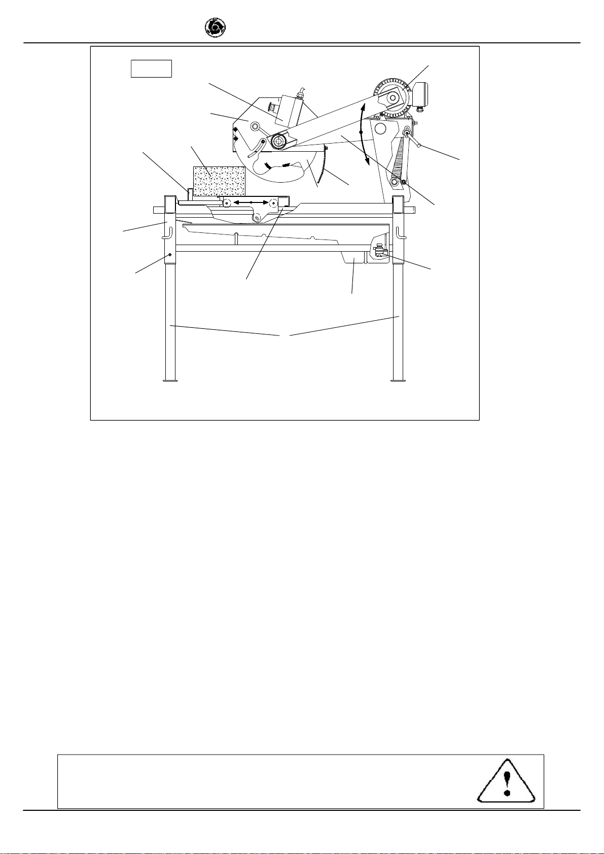
Fig. 1
D
1. Teleskoppfuss
2. Spritzschutz
3. Motor
4. Trennscheibenhalterung
5. Wasserpumpe
6. Gleitführung
7.Kontakglied
8. Werkstückschlitten
9. Wasserbecken
10. Sägeblattverkleidung
11. Halterungssperrgriff
12. Zu schneidendes Werkstück
13. Trennscheibe
14. Gestell
15. Erdungsschraube
F
1. Colonne télescopique
2. Bavolet
3. Moteur
4. Bras porte-lame
5. Pompe a eau
6. Coulisse
7. Contacteur
8. Chariot porte-pièce
9. Cuve a eau
10. Protection de la lame
11. Poignée de blocage du bras
12. Pièce à couper
13. Lame
14. Châssis
15. Vis de terre
GB
1. Telescopic leg
2. Spray guard
3. Motor
4. Blade support
5. Water pump
6. Guide
7. Contactor
8. Worktable
9. Water tank
10. Blade guard
11. Support locking handle
12. Work piece
13. Blade
14. Frame
15. Earth screw
I
1. Gamba telescopica
2. Grembialina paraschizzi
3. Motore elettrico
4. Braccio portadisco
5. Pompa acqua
6. Guida scorrimento
7. Magnetotermico
8. Carrello portapezzo
9. Vasca acqua
10. Protezione lama
11. Maniglia bloccaggio braccio
12. Pezzo da tagliare
13. Disco
14.Telaio
15. Vite di terra
E
1. Pie telescopico
2. Placa delantal salpicaduras
3. Motor
4. Brazo portahoja
5. Bomba del agua
6. Guia de deslizamiento
7. Contactor
8. Carro portapieza
9. Deposito de agua
10. Proteccion cuchilla
11. Manilla de bloqueo brazo
12. Pieza a cortar
13.Hoja
14. Bastidor
15. Tornillo de contacto de tierra

9
MASONRY 350 F
IMER INTERNATIONAL S.p.A.
Table2indicatesthenoiselevelproducedbythe sawing machine,
measured at the operator’s ear (LpA at 1 m - 98/37CE) and the
environmental noise emission level (power LWA) measured in
accordance with EN ISO 3744; UNI EN 12418.
GB GB
Dear Customer,
Congratulations on your choice of purchase: this IMER saw, the
result of years of experience, is a fully reliable machine and is
equipped with the latest technical innovations.
- WORKING IN SAFETY
To work in complete safety, read the following
instructions carefully.
-ThisOPERATIONANDMAINTENANCEmanualmustbekepton
site by the person in charge, e.g. the SITE FOREMAN, and must
always be available for consultation.
Thismanualistobe considered anintegralpartofthemachine,andit
must be preserved for future reference (EN292/2) throughout the
machine’s normal working life. If the manual is damaged or lost, a
replacement may be requested from the saw manufacturer.
- The manual contains important information regarding site
preparation, installation, machine use, maintenance procedures
and requests for spare parts. Nevertheless, the installer and the
operator must both have adequate experience and knowledge
of the machine prior to use.
- To guarantee complete safety of the operator, safe operation
and long life of equipment, follow the instructions in this manual
carefully, and observe all safety standards currently in force for
the prevention of accidents at work. Use personal protection
(safety footwear, suitable clothing, gloves, goggles, etc.).
- Safety glasses or a protective visor must be worn at all
times.
- Ear protection must be worn at all times.
- MAKE SURE THAT WARNING SIGNS ARE ALWAYS
LEGIBLE.
- It is strictly forbidden to carry out any form of
modification to the steel structure or working parts of the
machine.
- IMER INTERNATIONAL declines all responsibility for non-
compliance with laws and standards governing the use of this
equipment, in particular; improper use, defective power supply,
lack of maintenance, unauthorised modifications, and partial or
total failure to observe the instructions contained in this manual.
IMER INTERNATIONALis entitled to modifythe characteristics of
the sawing machine and/or the contents of this manual without
necessarily updating previous machines and/or manuals.
1. TECHNICAL DATA
Table 1 shows the saw’s technical data, referring to figure 1.
2. DESIGN STANDARDS
MASONRY350Fsawsaredesignedandmanufacturedaccordingto
the following standards: EN 292-1-2; EN 12418; EN 60204-1.
3. NOISE EMISSION LEVEL
TABLE 1
TECHNICAL DATA 1188793 1188797
Blade rpm rpm 1.980 1.910
Blade diameter mm 350
Blade mounting hole mm 25,4
Motor rating Kw 2,2 1,7
Voltage V 230 110
Current A 12 21
Frequency Hz 50
Motor rpm rpm 2.800 2.700
Cutting table dimension cm 50 x 43
Overall dimensions
(widthxlengthxheight) cm 86 x 118 x 136
Overall dimensions for
transport
(widthxlengthxheight) cm 83 x 125 x 98
Weight Kg 112
Weight for transport Kg 132
Blade rotation direction(seen
from blade clamping flange) CLOCKWISE
TABLE 2
SAWINGMACHINE TYPEOFMOTOR LpA
(dB) LWA
(dB)
Masonry350F EL ELECTRIC 86 98
4. CUTTING SPECIFICATIONS
This saw model has been specially designed for cutting stone,
ceramics, marble, granite, concrete and similar materials. Only
water-cooled diamond blades with continuous or segmented
edges (see paragraph 13) must be used. Under no
circumstances must dry cutting blades be used or materials
other than those specified above. IMER INTERNATIONAL
declines all responsibility for damage caused by improper use
of the above machine.
5. CUTTING CAPACITY
- max. cutting capacity with vertical blade = 120mm in one
single pass.
- max. height of workpiece: 230 mm (in two passes).
- min. width of workpiece: 50mm.
- max. cutting length: 470 mm (with blade lowered), 550 mm
(with blade fully raised).
-Blade at 45°: with support at 45° on the work surface.
6. WARNING
- Do not load the saw with workpieces that exceed the specified
weight (max. 40 kg)
- Ensure stability of machine: it must be installed on a solid
base with a maximum slope of 5° (fig. 2).
- Ensure the workpiece is stable before, during and after cutting:
in any case, workpieces must not overhang the worktable.
- Respect the environment; use suitable receptacles for
collection of cooling water contaminated with cutting dust.
7. SAFETY PRECAUTIONS
- IMER saws are designed for work on construction sites and
under conditions of natural light, hence the workplace must be
adequately lit.
- The machine must never be used in environments
subject to risks of explosion and/or underground sites
- IMER saws may only be used when fitted with all required
safety devices, which must be in perfect condition.
- Never use makeshift and/or faulty power cables.
- Make electrical connections on the construction site where
they will not be subject to damage. Never stand the saw on
power supply cables.
- Lay power cables in such a way as to prevent water
penetration. Only use connectors fitted with water-spray
protection (IP57, EEC).
- Repairs to electrical installations must only be carried out by
qualified technicians. Always ensure that the machine is
disconnected from the power supply and is completely immo-
bile during repairs and maintenance operations.
- Connect the machine to a suitable
equipotential earthing plant on the construction
site with wire braid of minimum 16 mm² section.
The connection point is identified by a screw
welded to the frame (Ref. 15, fig.1), and on the
rating plate by the earthing symbol.
- Stop the saw only by means of the main switch
(Ref. 7, fig. 1).
- The symbol shown on the label (see left)
indicates the warning “ENSURE ALL
PROTECTIONDEVICESAREINSTALLEDANDIN
PERFECTCONDITIONBEFORESWITCHINGON
THEMACHINE”(fig.3).
8. ELECTRICAL SAFETY
IMER saws comply with EN 60204-1; and are fitted with:
- Protection device against automatic re-start after power failure.
- Short-circuit cutout device
- Motor overload cutout switch
Fig. 3

10
MASONRY 350 F
IMER INTERNATIONAL S.p.A. GB
GB
9. TRANSPORTATION (fig. 4)
- WARNING! Before moving the saw, lock head
support carriage movement by means of the relative knob
(Ref. 11, fig. 1). Remove the plug from the power socket.
To transport the machine use slinging equipment with 4
rope legs, fixing the hooks to the relative attachments.
10. INSTALLATION (Fig. 4)
Lift the machine out of its package and fix the hooks to the
relative attachments on the machine.
- Unlock the legs by sliding out pins (ref.1).
-Lock thelegsat workingheight.Refitthe pinsinthe legsupports.
- Install the machine on a completely even and stable surface.
- Release the carriage from the lever that secures it to the frame.
11. ELECTRICAL CONNECTION
- Ensure that there is an overload cutout device
fitted up-line on the power line.
- Ensure that the mains voltage corresponds to that specified
for the machine: 230V/50Hz - 110V/50Hz. The electrical power
cable must be suitably sized to avoid voltage drops. Cable
drums must not be used.
Connect the machine to an efficient earthing system.
The size of the power cable wires must be based on operating
current and length of the power line to prevent excessive
voltage drops (ref.Table 3).
Cables used on construction sites must be fitted with suitable
external sheathing that is resistant to wear, crushing and
extreme weather conditions (for example H07RN-F).
- All power supply installations must comply with
CEI 64-8 standards (harmonised document CENELEC
HD384).
12. MACHINE START-UP
Before connecting the machine to the power supply:
1 - Ensure that the metal structure is connected to an earthing
plant as indicated in Section 7 “Safety Precautions”.
2 - Ensure that the tank contains sufficient cooling water.
3 - Ensure that the power circuit corresponds to the requirements
as indicated in Section 11 “Electrical connections”.
- RESIDUAL CURRENT CIRCUIT PROTECTION
(KIT 230V-P/N.1169245 ; KIT 110V-P/N.1169249):
It’s obligatory to fit the saw with the differential switch
kit P/N 1169249 on the feeding cable(ref.3, fig.7).
To start up the saw, press the green ON key on the RCCB
switch and an orange led illuminates (RCCB protection on).
RESIDUAL CURRENT CIRCUIT BREAKER TEST:
Press the black key TEST on the RCCB; the switch
disconnects and the orange led turns off.
After performing the TEST, press the ON key again to activate
theRCCB.
- Carry out the RCCB TEST before each machine
start-up.
4 - Connect the machine to the power supply
5 – Press the black switch (Ref.7, fig.1) after ensuring that
cooling water reaches the blade: adjust the flow of cooling water
by turning the cock next to the blade guard (do not perform
cutting without water).
6 - Check that the direction of blade rotation corresponds to that
indicated by the arrow on the blade guard.
7 - If all is in order, proceed with cutting.
13. EMERGENCY STOP
- In an emergency, stop the machine by pressing the
stop control switch.
- The motor is fitted with an overload cutout device.
If the motor overheats, it will automatically shut down.
Allow the motor to cool and press the black switch on the
overload cutout device to restart (Ref. 7, fig. 1).
- The motor is protected against automatic re-start
after interruptions due to power failure. To resume
operation, when power is re-connected, press the black
switch on the overload cutout device (Ref. 7, fig. 1).
14. BLADE INSTALLATION (Fig.5)
By means of a hex wrench no.10, loosen the 3 screws that secure
the blade guard (Ref. 3). Using a hex wrench no. 13, loosen the
screw that secures the flanges on the blade: this screw has a
left-hand thread (rif.1). Remove the mobile flange (rif.2) and check
that the flanges, disc shaft and blade are not damaged.
- Never use worn blades.
- Only use blades that are designed for the number
of revolutions indicated on the machine rating plate.
- Check that blade rotation corresponds to that
indicated on the blade guard.
Centre the blade against the fixed flange, position the mobile
flange and tighten the securing screw by means of a hex
wrench no. 13 (turn clockwise). Return the guard to its original
position, locking the 3 screws (Ref. 3).
- Ensure that the blade guard (Ref.3) is locked
securely into position.
- WARNING! An incorrectly installed blade or a
screw insufficiently tightened can provoke damage to
the machine or injury to persons.
- Note that the blade must have an
external diameter of 350 mm., a central
hole diameter of 25.4 mm and max.
thickness of 3 mm.
- Check that the blade to be used is
suitable for the material to be cut.
- Do not use blades for wood! (fig. 6).
15. USE
- Leave a space of 150 cm around the machine to ope-
rate in full safety.
-Donotallowotherpersonstoapproachthemachineduringcutting.
- Never use the machine in fire-risk areas. Sparks can cause fire or
explosions.
- Make sure that the machine is switched off before positioning or
handling.
- Always ensure that the blade is free of any contact before start-
up. - Ensure correct installation of all protective devices.
Before starting work, fill the water tank. Top up during operation
whenever necessary: N.B. the pump suction hose must
always remain immersed in water.
- Insert the plug in the power socket.
- WARNING! For safety purposes the removal of
protective guards from the machine is strictly prohibited
The machine is protected against overload: this protection
triggers stopping the machine, after which the time necessary
for the overload to cool must pass before it is possible to
restart the machine.
- WARNING! Always switch off the machine before
carrying out blade adjustment.
15.1 VERTICAL BLADE MOVEMENT
To raise or lower the blade, slacken the support locking handle
turning it anti-clockwise (Ref. 11, fig. 1). The blade support (Ref. 4,
fig.1) remains free to rotate, so it can be secured in the desired
position, fully tightening the handle (ref. 11, fig. 1).
- Ensure that the locking handle is tightened fully before
starting work.
15.2 BLADE POSITIONING FOR 45° CUTS
To makea cut at 45°, the 45° support on the carriage is necessary.
Oncetheworkpieceiscorrectlypositioned,cuttingcanbegin,starting
the electric motor.
15.3 CUTTING
For safe use of the machine when cutting, push the carriage
forwards as the cut advances, placing your hands to the two
sides of the carriage. Never push directly on the piece to be cut.
Fig. 6

11
MASONRY 350 F
IMER INTERNATIONAL S.p.A. GB
GB
- Check that the blade is aligned with the cutting line.
- Place the workpiece on the worktable (ref. 8, fig. 1), resting firmly
against the stop. Start the motor.
Wait until the water reaches the blade. Begin cutting.
- Horizontal cutting movement is carried out by pulling the carriage
towards the blade.
-As cutting thickness increases, the blade is subjected
to greater stress. To avoid overloading the motor, the
operator should continually check blade feed speed. The
speed will also depend on the characteristics of the
material being cut (hardness, toughness etc.).
15.3.1 CUTS WITH BLADE LOWERED FROM ABOVE
Bring the blade support to its highest position and lock. Position the
workpiece.Start themachine, unlock the bladesupportand begin
vertical cutting until the blade reaches its lowest point. Lock the
support once more and proceed with horizontal cutting
15.3.2 BLADE CHANGE
To change the blade refer to section 13.
16. MAINTENANCE
- WARNING! Servicing must always be carried out by
qualified technicians and only after the motor has been
switched off.
- Always keep the guards in proper working order
and free from damage. Take particular care to ensure
that the blade guards are kept efficient and clean,
replacing them if they are damaged.
- As there is the continuous risk of inadvertent
damage to the electric cables, these must be checked
regularly each time before the machine is used.
Never leave the machine out in the open. Make sure that it is
stored in a sheltered area away from extreme weather
conditions.
Below is a list of the cleaning operations that must be carried out
at the end of every shift.
16.1 TANK CLEANING ON WORK COMPLETION
- Empty the tank by removing the plug. Remove cutting residue
using a jet of water.
16.2 TANK REMOVAL (Fig.7).
- Lift the tank (ref.1) to detach from its supports (ref.2) and
remove from the side indicated by the arrow.
16.3 WORK SURFACE CLEANING
Alwayskeep work surfaces clean. Residual dirt can impair cutting
precision.
16.4 GUIDE RAIL CLEANING
It is good practice to remove all traces of dirt from the guides.
16.5 CLEANING AND MAINTENANCE OF COOLING
CIRCUIT
- If water does not reach the blade stop the machine immediately
to avoid blade damage.
-Afterswitchingoffthemachineensurethatthewaterlevelissufficient.
- If necessary, after disconnecting the machine from the power
supply check that the tap, hose and pump filter are not blocked
- If necessary, check that the impeller rotates freely (after
extended periods of disuse)
16.6 TENSIONING THE DRIVE BELT (fig. 8)
- Switch off the electric motor and remove the plug from the
power supply.
- Unscrew the 4 screws that secure the movable belt guard (ref. 1).
- Loosen the 4 (ref. 2) screws that clamp the electric motor to
the blade support.
- Tension the belt using the nut (ref. 3): apply a force of about
F=6 Kg to the centre of the free section of the belt, the arrow
should be about f=6 mm (fig. 9).
-Tightenthe screws on the electric motor,checking the alignment
of the motor pulley and the blade pulley
- Refit the guard and lock it using the 4 screws.
- To avoid shortening the life of the belt, the bearings
and the blade shaft, do not overtension the belt. Finally,
check the two pulleys are aligned.
16.7 DRIVE BELT REPLACEMENT
Repeat the operations described in section 16.6, replacing the
belt before tensioning it
17. REPAIRS
- Do not start the saw during repair work.
Onlyuse genuine IMER spare parts and do notmodify them.
- If the guards are removed to carry out repairs, they
must be refitted properly when the repair work is finished.
18. TROUBLESHOOTING
- WARNING! Before carrying out any maintenance
operations, switch off the machine, and remove the plug
from the power socket.
FAULT CAUSE REMEDY
Motor does not start
when switch is
turned
- Defective power
cable
- Plug not inserted in
socket correctly
- Power cable from
plug to control panel
detached
- Loose wire inside
motor circuit board
- A wire has become
disconnected inside
the panel
- Faulty main switch
-The overload safety
device has been
activated.
- Check power cables
- Ensure correct
connection
- Connect cable- re
-Connect wire
- Remake the
connection
- Replace switch
-Wait for a fewminutes
and then try restarting
the machine.
Vertical blade
movement not
smooth
- locking knob too tight - Slacken knob
Horizontal carriage
movement not
smooth
- Guide rails dirty - Clean the guide rails
Lack of cooling water
supply to blade Refer to section 16.5: "cleaning and
maintenance of cooling circuit" (Chapter 16.5)
Blade does not cut
- Blade is worn
- Drive belt not
tensioned
- Fit newblade
-Tension the belt
Motor starts but
blade does not rotate Belt is broken Replace drive belt

18
MASONRY 350 F
IMER INTERNATIONAL S.p.A.
Fig. 4
11
Fig. 8
Fig. 9
1
1
2
3Masonry 350 F - Tab. 3
Lunghezza cavo (m)
Longueur câble (m)
Cable length (m)
Kabel Länge (m)
Longitud cable (m)
V 230
I= 12 A 0 ÷ 14 15 ÷ 23 24 ÷ 37
V110
I= 21 A 0 ÷ 8 9 ÷ 14 15 ÷ 22
sezione cavo (mm²)
section câble (mm²)
cable (mm²)
kabel (mm²)
cable (mm²)
1.5 2.5 4
Fig.2
5° MAX
Fig.5
2
1
Fig. 7
2

19
MASONRY 350 F
IMER INTERNATIONAL S.p.A.
RICAMBI:Pertuttigliordinideipezzidiricambiovogliateindicare:1- Tipodimacchina.2 - Numerodicodicee diriferimentocollocatoincorrispondenzadiognidefinizione.3-Numerodiserie
eannodicostruzioneriportatosullatarghettadellamacchina.SIMBOLOGIA:Intercambiabilità(esempio):Finoallamacchina matricolaN°5240èstatoinstallatoilrif.1cod.3204530,dallamcchina
matricolaN° 5241è statoinstallatoilrif.1.1cod.3204520.Ilrif.1.1è intercambiabile( )conil rif.1.Nonsonointercambiabiliirif.1e rif.1.1seintabellaèpresenteilsimbolo( ).
PIECESDERECHANGE:Pourtouteslescommandesdepiècesderechange,veuillezindiquer:1-LeTypedemachine2-LeNumérodecodeetderéférencesetrouvantenfacedechaquedéfinition
3- LeNumérodesérieetl'annéedeconstructionsetrouvantsurlaplaquetted'identificationdelamachine
SYMBOLOGIE:Intercambiabilità(exemple):Jusqu'àlamachinematriculeN°5240,nousavonsinstallélaréf.1code3204530;àpartirdelamachinematriculeN°5241,nousavonsinstallélaréf.
1.1code3204520.Laréf.1.1estinterchangeable( )aveclaréf.1.Lesréf.1etréf.1.1nesontpasinterchangeblessilesymbole( )n'estpassurletableau.
SPARE PARTS:Allordersforsparepartsmustindicatethefollowing:1 -Typeofmachine.2-Partnumberandpositionnumberofeachpart.3-Serialnumberandyearofmanufacturereported
onthemachine'sidentificationplate.
SYMBOL:Interchangeability(example):Pos..1P.n.3204530wasinstalledonmachincsuptoN°5240andPos.1.1P.n.3204520installedonmachineN°5241onwards.Pos.1.1isinterchangeable
( ) with Pos. 1.Pos. 1 and Pos. 1.1are not interchangeable if the ( )symbol appears in the table.
ERSATZTEILE:FürErsatzteilbestellungenbittediefolgendenAngabenmachen:1)Maschinentyp2)JeweilszugeordneteArt.-Nr.undPositionsnummer3)SeriennummerundBaujahr(Angabeaufdem
Maschinenschild)
SYMBOLE:Austauschbarkeit(Beispiel):BiszurMaschinenummer5240istRef.1Cod.3204530undabMaschinennummer5241istRef.1.1Cod.3204520installiertworden.Ref.1.1undRef.1sindaustaschbar
( ).Ref.1undRef.1.1sindnichtaustauschbar,wenndasSymbol( )angegebenist.
PIEZASDERECAMBIO:Parapedirunapiezaderecambiohayqueindicarsiempre:1-Eltipodemáquina.2-Losnúmerosdegódigoydereferenciaindicadosencorrespondenciadecadadefinición.3-Elnúmero
deserieyelañodeconstrucciónindicadosenlaplacadelamáquina.
SIMBOLOGIA:Intercambiabilidad(ejemplo):HastaelequipoconmatrìculaN°5240,sehainstaladolapiezaconref.1ycòd.3204530;apartirdelamàquinaconmatrìculaN°5241,sehainstaladolapiezacon
ref.1.1ycòd.3204520.Lapiezaconref.1.1sepuedeintercambiar( )conlapiezaconref.1.Sientablasehallapresenteelsìmbolo( ),laspiezascoreferencia1y1.1nosonintercabiables.
Rif. Cod. I F GB D E Note
1 3204530 Riduttore Réducteur Reducer Untersetzungsgetriebe Reductor 5240
2 3204520 Riduttore Réducteur Reducer Untersetzungsgetriebe Reductor 5241
OPTIONAL
TAV.1
TAV. 1 KIT RUOTE - KIT DE ROUES - WHEEL KIT - RÄDER - SATZ - KIT DE RUEDAS
Rif. Cod. I F GB D E Note
1 2226700 COPIGLIA GOUPILLE SPLIT PIN KLAPPSPLINT CHAVETA
2 2211150 RUOTA ROUE WHEEL RÄDER RUEDA
3 3206261 GUIDA SCORRIMENTO
TUBO SX COULISSE DU TUYAU
G.CHE LEFT TUBE GUIDE GLEITFÜHRUNG ROHR
LINKS
GUÍA
DESPLAZAMIENTO
TUBO IZQUIERDO
4 3206262 GUIDA SCORRIMENTO
TUBO DX COULISSE DU TUYAU
DROIT RIGHT TUBE GUIDE GEITFÜHRUNG ROHR
RECHTS
GUÍA
DESPLAZAMIENTO
TUBO DERECHO
5 2222082 VITE VIS SCREW SCHRAUBE TORNILLO 5739 M 10X60 Z
6 2223650 DADO ECROU DISK MUTTER TUERCA 5588 M10 Z
7 3206641 ROSETTA RONDELLE WASHER UNTERLEGSCHEIBE ARANDELA 6592 28X50X2 Z
8 3206260 TUBO RUOTE TUYAU ROUES WHEEL TUBE RÄDERROH TUBO RUEDAS

20
MASONRY 350 F
IMER INTERNATIONAL S.p.A.
TAV.2
TAV.2TAV.2
RIF. COD. I F GB D E NOTE
1 3208421 CARRELLO CHARIOT CARRIAGE WAGEN CARRO
2 2222061 VITE VIS BOLT SCHRAUBE TORNILLO 5739 M 8X20 Z
3 2222515 VITE VIS BOLT SCHRAUBE TORNILLO 5931 M 8X16 Z
4 3204945 CUSCINETTO ROULEMENT BEARING LAGER COJINETE 608-2RS1
5 2223923 DADO AUTOBLOCCANTE ECROU DE SÛRET! SELF LOCKING
NUT SELBSTSICHERNDE
MUTTER TUERCA
AUTOBLOQUEANTE M 8
6 3207397 RUOTA ROUE WHEEL RAD RUEDA
7 2222090 VITE VIS BOLT SCHRAUBE TORNILLO 5737 M 8x75 Z
8 3210193 GUIDA GLISSIERE GUIDE BAR FÜHRUNG GUÍA
9 3208442 ADESIVO BATTUTA
SINISTRA ADHESIF BUTÉE
GAUCHE LEFT FENCE
ADHESIVE LABEL SCHILD LINKER
ANSCHLAG ADHESIVO TOPE
IZQUERDO
10 3208441 ADESIVO BATTUTA
DESTRA ADHESIF BUTÉE
DROITE RIGHT FENCE
ADHESIVE LABEL SCHILD RECHTER
ANSCHLAG ADHESIVO TOPE
DERECHO
11 3205581 RIVESTIMENTO GOMMA REVETEMENT IN
CAOUTCHOUC RUBBER
COAITING GUMMI BEKLEIDUNG GOMA REVESTIMIENTO
12 2224612 ROSETTA RONDELLE WASHER UNTERLEGSHEIBE ARANDELA D.21X43 Z
13 3206086 PERNO PIVOT PIN ZAPFEN PERNO
14 3201517 GAMBA PIED LEG FUB PATA
15 3210350 GRUPPO TESTA DI
TAGLIO GROUPE TêTE DE
COUPE CUTTING HEAD
GROUP SCHNEIDKOPF-GRUP-
PE GRUPO CABEZA DE
CORTE
16 3206096 SUPPORTO SUPPORT SUPPORT UNTERLAGE SOPORTE
17 2223920 DADO
AUTOBLOCCANTE ECROU DE SURETE SELF LOCKING
NUT SELBSTSICHERNDE
MUTTER TUERCA
AUTOBLOCANTE M 10
18 3201015 TAPPO BOUCHON PLUG STOFFEN TAPON
19 2222587 VITE VIS SCREW SCHRAUBE TORNILLO 5933 M8X20 Z
20 3210171 PARASCHIZZI PROTECTION
ÉCLABOUSSURES SPRAY GUARD GUMMISPRITZSCHUTZ PROTECCIÓN CONTRA
SALPICADURAS
21 3210169 TELAIO CHASSIS FRAME RAHMEN BASTIDOR
22 3205526 CONVOGLIATORE TOBOGGAN WATER RUN-OFF
TRAY FÖRDERER TRANSPORTADOR
23 2222425 VITE VIS SCREW SCHRAUBE TORNILLO AUTOFOR.TE 4,2X13
24 3204818 VASCA CUVE DRUM MISCHWANNE RECIPIENTE
25 2235428 TAPPO BOUCHON PLUG STOFFEN TAPÓN

21
MASONRY 350 F
IMER INTERNATIONAL S.p.A.
TAV.2TAV.2
RIF. COD. I F GB D E NOTE
26 3210360 POMPAACQUA POMPE EAU WATERPUMP WASSERPUMPE BOMBADELAGUA 230V-50Hz
3210378 110V-50Hz
27 2292365 TUBO TUBE TUBE ROHR TUBO L=1.3 m.
28 2224320 ROSETTA RONDELLE WASHER UNTERLEGSCHEIBE ARANDELA D.10X21X2
29 3210161 ALBEROTRASMISSIONE ARBRE SHAFT WELLE EJE
30 2209450 BOCCOLANYLON DOUILLENYLON NYLONBUSHING NYLON-BUCHSE MANGUITONYLON
31 2222002 VITE VIS SCREW SCHRAUBE TORNILLO 5739M6x16Z
32 2222059 VITE VIS SCREW SCHRAUBE TORNILLO 5739M8X25ZSX.
33 3208414 LEVAASCATTO LEVIER LEVER HEBEL PALANCA
34 3208422 GONIOMETRO GONIOMÈTRE GONIOMETER WINKELMESSER GONIÓMETRO
35 3207213 SUPPORTOFISSAGGIO
GUIDE SUPPORTGLISSIERE GUIDEBAR
SUPPORT FUHRUNGINTERLAGE GUIASUPORTE
36 3208428 SLITTACARRELLO CHARIOTGLISSIÈRE TROLLEYSLIDE KARRESCHLITTEN CARROCORREDERA
37 3210236 SUPPORTOFISSAGGIO
GUIDESX SUPPORT GLISSIERE
SX GUIDEBAR
SUPPORTSX FUHRUNGINTERLAGE
SX GUIASUPORTE SX
38 2222580 VITE VIS SCREW SCHRAUBE TORNILLO M4X20Z
39 3210153 ASTAROTAZIONE
CARTERDISCO TIGERéGLAGE
ROTATION ROTATION
ADJUSTINGROD DREH-REGULIERSTA-
NGE ASTAREGLAJEROTACIóN
40 3209333 POMELLO POIGNÉE KNOB KNOPF POMO M8Z
41 3210644 BLOCCAGGIO
CARRELLO CHARIOTCALAGE TROLLEYCLAMPING KARREEINSPANNUNG CARROBLOQUEO
42 2222016 VITE VIS SCREW SCHRAUBE TORNILLO 5739M6x20Z
43 2223924 DADO ECROU NUT MUTTER TUERCA M6 Z
44 3209332 ECCENTRICO EXCENTRIQUE CAM EXZENTERBUCHSE EXCÉNTRICO
45 2222018 VITE VIS SCREW SCHRAUBE TORNILLO 5931M8X35Z
46 2224534 ROSETTA RONDELLE WASHER UNTERLEGSCHEIBE ARANDELA 6X12.5Z
47 3210163 PULEGGIA POULIE PULLEY RIEMENSCHEIBE POLEA
48 3210354 QUADROELETTRICO BOITERELECTRIQUE JUNCTIONBOX GEHAUSE CAJAELECTRA 230V/50HZ
3210376 110V/50HZ
49 2288885 MANOPOLA POIGNÉE HANDGRIP GRIFF EMPUÑADURA
50 3206513 CUSCINETTO PALIER BEARING LAGER COJINETE 62052RS
51 3210179 CARTERDISCO CARTERDISC DISCCOVER SCHEIBENGEHäUSE CÁRTER
52 3232759 ANELLOPARAOLIO BAGUED'ÉTANCHÉITÉ OILSEALRING ÖLABSTREIFRING ANILODERÉTEN 35X52X7
53 3204777 FLANGIAINTERNA FLASQUEINTÉRIEURE INNERFLANGE FLANSCHINN. BRIDAINTERIOR
54 3204776 FLANGIAESTERNA FLASQUEEXTÉRIEURE OUTERFLANGE FLANSCHAUSS. BRIDAEXTERIOR
55 3210156 UGELLOACQUA TUYAUEAU WATERHOSE WASSERDüSE TUBOAGUA
56 3210629 CUSCINETTO PALIER BEARING LAGER COJINETE 60062RS
57 3205635 RUBINETTO ROBINET VALVE HAHN GRIFO
58 3210140 CARTERLAMA CARTERLAME BLADE COVER SCHEIBENGEHÄUSE CÁRTERHOJA
59 2222006 VITE VIS SCREW SCHRAUBE TORNILLO M8X30Z
60 3210189 DADO
AUTOBLOCCANTE ECROUDESURETE SELFLOCKING NUT SELBSTSICHERNDE
MUTTER TUERCA
AUTOBLOCANTE M20Z
62 3204889 LEVAASCATTO LEVIER LEVER HEBEL PALANCA
63 2229300 LINGUETTA LANGUETTE KEY KEIL LENGUETA 6X6X20
64 2224910 ROSETTA RONDELLE WASHER UNTERLEGSCHEIBE ARANDELA DEV.D.10Z
65 3210142 ASTAREGOLAZIONE
ROTAZIONE TIGEROTATION
CARTERDISQUE BLADEGUARD
ROTATIONROD
DREHSTANGEDER
SCHUTZHAUBE-TREN-
NSCHEIBE
ASTAREGLAJEROTACIóN
GUARDADISCO
66 3210152 MOLLA RESSORT SPRING FEDER MUELLE
67 2227320 ANELLOARRESTO BAGUE D'ARRÊT STOPRING ARRETIERRING ANILLODEPARADA E/20
68 3210181 PERNOMOLLA PIVOTRESSORT SPRINGPIN FEDER PERNOMUELLE
69 3210206 PARASCHIZZIDISCO PROTECTION
ÉCLABOUSSURES SPRAYGUARD GUMMISPRITZSCHUTZ PROTECCIÓNCONTRA
SALPICADURAS
70 3210353 VITETIRANTE VIS TIRANT TIE RODSCREW TRÄGER TORNILLOTIRANTES
71 3210542 PROTEZIONEDXDISCO PROTECTION DISQUE DX DISK PROTECTION DX SCHUTZSCHEIBE PROTECCIÓN DISCO DX
72 3210543 PROTEZIONESXDISCO PROTECTION DISQUE SX DISK PROTECTION SX SCHUTZSCHEIBE PROTECCIÓN DISCO SX
73 3210576 ROSETTA NYLON RONDELLENYLON NYLONWASHER UNTERLEGSCHEIBE ARANDELANYLON 8.4XX17X1.5
74 2224140 ROSETTA RONDELLE WASHER UNTERLEGSCHEIBE ARANDELA 8X18Z.
75 2222110 VITE VIS SCREW SCHRAUBE TORNILLO 8X80 Z

22
MASONRY 350 F
IMER INTERNATIONAL S.p.A.
TAV.3TAV.3
RIF. COD. I F GB D E N OTE
13210355 MOTORE MOTEUR MOTOR MOTOR MOTOR 230V/50Hz
3210377 110V/50Hz
2 3210162 CARTER CINGHIE
INTERNO CARTER EXTÉRIEUR
COURROIS BELTS EXTERNAL
COVER RIMEN
AUSSENSCHUTZHAUBE CÁRTER EXTERIOR
CORRERAS
3 3210185 CINGHIA COURROIE BELT RIEMEN CORREA 470 J 12
4 3210164 CARTER CINGHIE
ESTERNO CARTER INTÉRIEUR
COURROIS BELTS INTERNAL
COVER RIMEN
INNENSCHUTZHAUBE CÁRTER INTERIOR
CORRERAS
5 3210165 STAFFA SUPPORTO
CARTER CINGHIE ÉTRIER SUPPORT
CARTER COURROIS
SUPPORT
BRACKET FOR
BELTS COVER
BUGELHALTERUNG
DER
RIEMENSCHUTZHAUBE
ESTRIBO SOPORTE
CÁRTER CORREAS
6 3210460 CASSETTA ELETTRICA BOITER ELECTRIQUE JUNCTION BOX GEHAUSE CAJA ELECTRCA
72285601 CONDENSATORE CONDENSATEUR CAPACITOR KONDENSATOR CONDENSADOR 230V/50Hz (µF 35)
3213013 110V/50Hz (µF 120)
8 2222002 VITE VIS BOLT SCHRAUBE TORNILLO M 6X16 Z
9 2224530 ROSETTA RONDELLE WASHER UNTERLEGSCHEIBE ARANDELA 6X12.5 Z
10 2223924 DADO
AUTOBLOCCANTE ECROU DE SURETE SELF LOCKING
NUT SELBSTSICHERNDE
MUTTER TUERCA
AUTOBLOCANTE M 6 Z
11 3203921 VITE VIS BOLT SCHRAUBE TORNILLO M 5X10 Z
12 2224140 ROSETTA RONDELLE WASHER UNTERLEGSCHEIBE ARANDELA 8X18 Z
13 2223923 DADO
AUTOBLOCCANTE ECROU DE SURETE SELF LOCKING
NUT SELBSTSICHERNDE
MUTTER TUERCA
AUTOBLOCANTE M 8 Z
14 2222176 VITE VIS BOLT SCHRAUBE TORNILLO M 8X50 Z
15 2222004 VITE VIS BOLT SCHRAUBE TORNILLO M 8X35 Z
16 2227320 ANELLO ARRESTO BAGUE D'ARR T STOP RING ARRETIERRING ANILLO DE PARADA E 20
17 3210157 PULEGGIA POULIE PULLEY RIEMENSCHEIBE POLEA
TAV .3
TAV.4TAV.4
RIF. COD. I F GB D E NOTE
1 3210462 CASSETTA ELETTRICA BOITER ELECTRIQUE JUNCTION BOX GEHAUSE CAJA ELECTRA
23207920 MAGNETOTERMICO CONTACTEUR CONTACTOR KONTAKGLIED CONCTACTOR 230V/50 Hz
3207922 110V/50 Hz
3 3207928 PULSANTE BOUTON PUSH DRUCKKNOPF PULSANDOR
4 3210356 PIASTRA QUADRO
ELETTRICO PLAQUE PANNEAU
ÉLECTRIQUE ELECTRIC PANEL
PLATE
PLATTE DER
ELEKTRISCHEN
SCHALTTAFEL
CHAPA QUADRO
ELÉCTRICO
53207923 BOBINA DI MINIMA BOBINE COIL SPULE BOBINA 230V/50 Hz
3207926 110V/50 Hz
TAV. 4

23
MASONRY 350 F
IMER INTERNATIONAL S.p.A.
SCHEMA ELETTRICO / SCHEMA ELECTRIQUE / WIRING DIAGRAM / SCHALTPLAN / ESQUEMA ELECTRICO
I F GB D E
L1 CONDUTTORE DI LINEA
FASE CONDUCTEUR DE LIGNE
PHASE PHASE LINE
CONDUCTOR PHASENLEITER CONDUCTOR DE LINEA
FASE
NCONDUTTORE DI LINEA
NEUTRO CONDUCTEUR DE LIGNE
NEUTRE NEUTRAL LINE
CONDUCTOR MITTELLEITER CONDUCTOR DE LINEA
NEUTRO
PE CONDUTTORE DI
PROTEZIONE CONDUCTEUR DE
PROTECTION TERRE PROTECTION
CONDUCTOR SCHUTZLEITER CONDUCTOR DE
PROTECCION
I1 INTERRUTTORE
MAGNETOTERMICO INTERRUPTEUR
MAGNÉTOT THERMO-MAGNETIC
CUTOUT SWITCH SCHUTZSCHALTER INTERRUPTOR
MAGNETOTÉRMICO
C1 CONDENSATORE MARCIA CONDENSATEUR MOTOR CAPACITOR KONDENSATOR GANG CONDENSADOR DE
MARCHA
K1 BOBINA BOBINE COIL SPULE BOBINA
M1 MOTORE LAMA MOTEUR LAME BLADE MOTOR SÄGEBLATTMOTOR MOTOR DE LA
CUCHILLA
M2 MOTORE POMPA MOTEUR POMPE PUMP MOTOR PUMPENMOTOR MOTOR DE LA BOMBA
TAV.5 SUPPORTO 45° - SUPPORT 45° - 45° SUPPORT - SOPORTE 45°- UNTERLAGE45°
Rif. Cod. I F GB D E Note
1 2284859 POMELLO POIGNEE KNOB KNOPS POMO
TAV. 5
PROTEZIONE DIFFERENZIALE
KIT 230V - Cod.1169245
KIT 110V - Cod.1169249
OPTIONAL
Table of contents
Other IMER Sewing Machine manuals


