20
(R5)
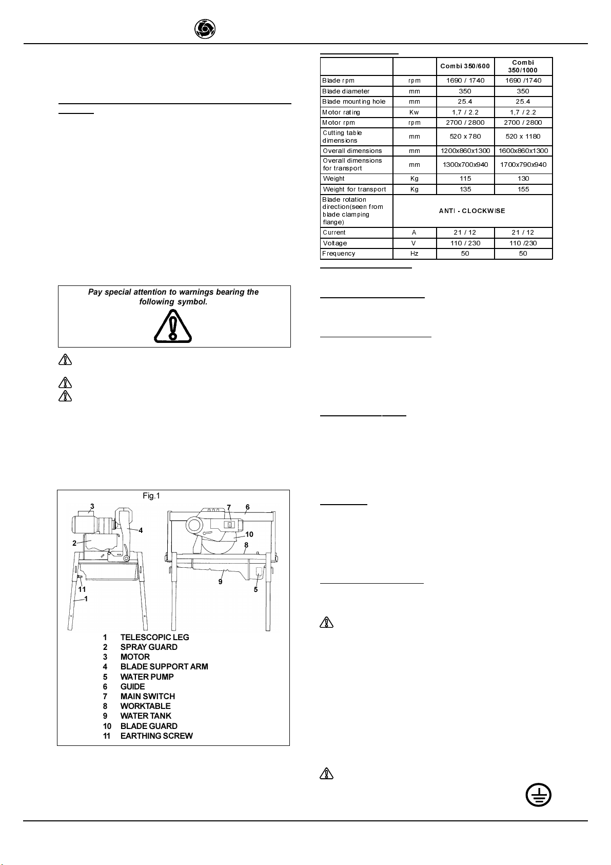
COMBI 350/600 - 350/1000
IMER INTERNATIONAL S.p.A.
$.
$.
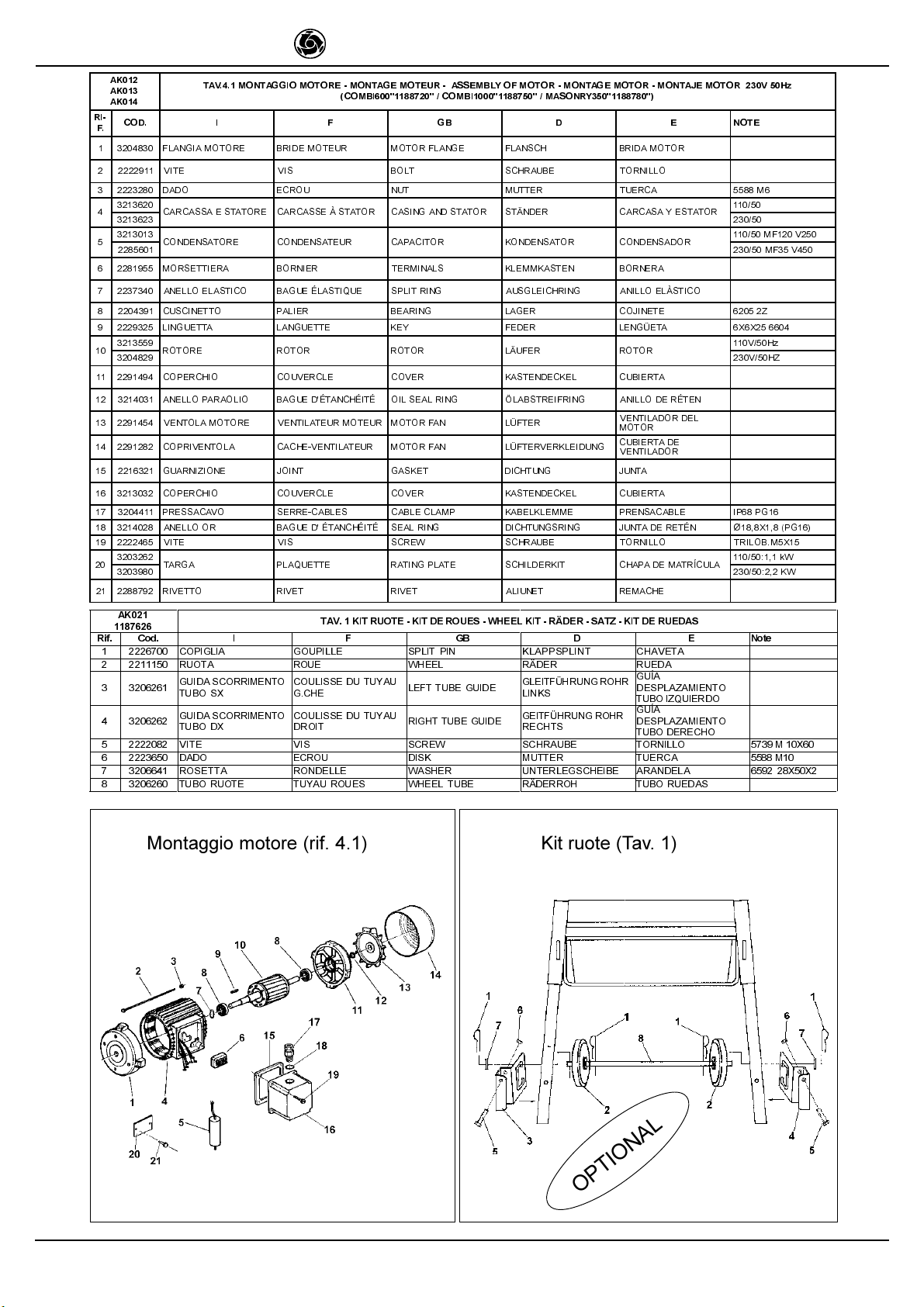
$. 7$90217$**,202725,==$=,21(0217$*(027(85$66(0%/<2)027250217$*(02725,6,(581*0217$-(02725
5,) &2' , ) *% ' ( 127(
&21'(16$725( &21'(16$7(85 &$3$&,725 .21'(16$725 &21'(16$'25 9+]0)9
9+]0)9
&217$7725( &217$&7(85 &217$&725 .217$.*/,(' &217$&725 9+]
9+]
%2%,1$ %2%,1( &2,/ 638/( %2%,1$ 9+]
9+]
35(66$&$92 6(55(&$%/(6 &$%/(&/$03 .$%(/./(00( 35(16$&$%/(
&23(5&+,2 &289(5&/( &29(5 .$67(1'(&.(/ &8%,(57$
*8$51,=,21( -2,17 *$6.(7 ',&+781* -817$
9,7( 9,6 %2/7 6&+5$8%( 7251,//2
02725( 027(85 02725 02725 02725 9+]
9+]
(7,&+(77$ (7,48(77( /$%(/ ./(%(=(77(/ (7,48(7$
&$66(77$(/(775,&$ %2,7(5(/(&75,48( -81&7,21%2; *(+$86( &$-$(/(&75&$
38/6$17( %28721 386+ '58&..123) 38/6$'25
*8$51,=,21( -2,17 *$6.(7 ',&+781* -817$
9,7( 9,6 %2/7 6&+5$8%( 7251,//2
35(66$&$92 6(55(&$%/(6 &$%/(&/$03 .$%(/./(00( 35(16$&$%/(
63,1$ ),&+( 3/8* 67(&.(5 (1&&+8)( 9+]
9+]
$.
$.
7$90217$**,27(67$26&,//$17(0217$*(77(26&,//$17(02%,/(+($'$66(0%/<0217$*('(6
6&+:,1*.23)(6
0217$-('(/&$%(=$/26&,/$17(
5,) &2' , ) *% ' ( 127(
0$1,*/,$ 32,*1e( +$1'/( *5,)) 0$1,//$
526(77$ 521'(//( :$6+(5 817(5/(*6&+(,%( $5$1'(/$ ;
9,7( 9,6 %2/7 6&+5$8%( 7251,//2 0;
'$'2 (&528 187 0877(5 78(5&$ 0
&23(5&+,2 &289(5&/( &29(5 .$67(1'(&.(/ &8%,(57$
9,7( 9,6 %2/7 6&+5$8%( 7251,//2 0;
&86&,1(772 528/(0(17 %($5,1* /$*(5 &2-,1(7( 56
526(77$ 521'(//( :$6+(5 817(5/(*6&+(,%( $5$1'(/$ ;
526(77$ 521'(//( :$6+(5 817(5/(*6&+(,%( $5$1'(/$ 66',1
;;
&2532
7 ( 1 ' ,& ,1 * + ,$ &25367(1'(85
&28552,( %(/77(16,21(5
81,7 .g53(5
5,(0(163$11(5 &8(5327(1625'(
&255($
9,7( 9,6 %2/7 6&+5$8%( 7251,//2 0;
'$'2 (&528 187 0877(5 78(5&$ $870
02//$ 5(66257 635,1* )('(5 08(//(
&86&,1(772 528/(0(17 %($5,1* /$*(5 &2-,1(7( 56
&,1*+,$ &28552,( %(/7 5,(0(1 &255($
38/(**,$ 328/,( 38//(< 5,(0(16&+(,%( 32/($
38/(**,$ 328/,( 38//(< 5,(0(16&+(,%( 32/($
9,7( 9,6 %2/7 6&+5$8%( 7251,//2 0;
)8/&527(67$7$ 3,9277(7( +($')8/&580 .23)'5(+381.7 $32<2'(/
&$%(=$/
&86&,1(772 528/(0(17 %($5,1* /$*(5 &2-,1(7( 56
63,12772 *283,//( 3,1 %2/=(1 3$6$'25
3(512 3,927 3,1 =$3)(1 3(512
02//$ 5(66257 635,1* )('(5 08(//(
$/%(52/$0$ $5%5(/$0( %/$'(6+$)7 0(66(5:(//( (-('(/$+2-$
/,1*8(77$ /$1*8(77( .(< )('(5 /(1*h(7$ $;;
&86&,1(772 528/(0(17 %($5,1* /$*(5 &2-,1(7( 56
$1(//23$5$2/,2 %$*8('e7$1&+e,7e 2,/6($/5,1* g/$%675(,)5,1* $1,/2'(5e7(1 ;;
&(51,(5$ &+$51,e5( &/$63 6&+$51,(5 %,6$*5$
9,7( 9,6 %2/7 6&+5$8%( 7251,//2 75,/2%7&3+
0;1
9,7( 9,6 %2/7 6&+5$8%( 7251,//2 0;
526(77$ 521'(//( :$6+(5 817(5/(*6&+(,%( $5$1'(/$ ;
'$'2 (&528 187 0877(5 78(5&$ $872%/0
3$5$6&+,==, 3527(&7,21
(&/$%286685(6 635$<*8$5' 635,7=6&+87= 3527(&&,Ï1
&2175$
6$/3,&$'85$6
58%,1(772 52%,1(7 9$/9( +$+1 *5,)2
78%2 78<$8 78%( :$66(56&+/$8&+ 78%2
9,7( 9,6 %2/7 6&+5$8%( 7251,//2 0;
68332572 6833257 6833257 817(5/$*( 623257(
35(66$&$92 6(55(&$%/(6 &$%/(&/$03 .$%(/./(00( 35(16$&$%/(
35(66$&$92 6(55(&$%/(6 &$%/(&/$03 .$%(/./(00( 35(16$&$%/(
0$1,*/,$ 32,*1e( +$1'/( *5,)) 0$1,//$ &20%,0$6215<
&20%,
9,7( 9,6 %2/7 6&+5$8%( 7251,//2 0;
)/$1*,$,17(51$ )/$648(,17e5,(85( ,11(5)/$1*( )/$16&+,11 %5,'$,17(5,25
)/$1*,$(67(51$ )/$648(
(;7e5,(85( 287(5)/$1*( )/$16&+$866 %5,'$(;7(5,25
526(77$ 521'(//( :$6+(5 817(5/(*6&+(,%( $5$1'(/$ ;
9,7( 9,6 %2/7 6&+5$8%( 7251,//2 0;
&$57(5/$0$ &$57(5/$0( %/$'(&29(5 6&+(,%(1*(+b86( &È57(5+2-$
9,7( 9,6 %2/7 6&+5$8%( 7251,//2 0;
(7,&+(77$ (7,48(77( /$%(/ ./(%(=(77(/ (7,48(7$
9,7( 9,6 %2/7 6&+5$8%( 7251,//2
*8$51,=,21( -2,17 *$6.(7 ',&+781* -817$
526(77$ 521'(//( :$6+(5 817(5/(*6&+(,%( $5$1'(/$ [[
$00257,==$725( $0257,66(85 6+2&.
$%625%(5 :,5.(1'(5
672'b03)(5 $0257,*8$'25
9,7( 9,6 %2/7 6&+5$8%( 7251,//2 0;=
526(77$ 521'(//( :$6+(5 817(5/(*6&+(,%( $5$1'(/$ ;