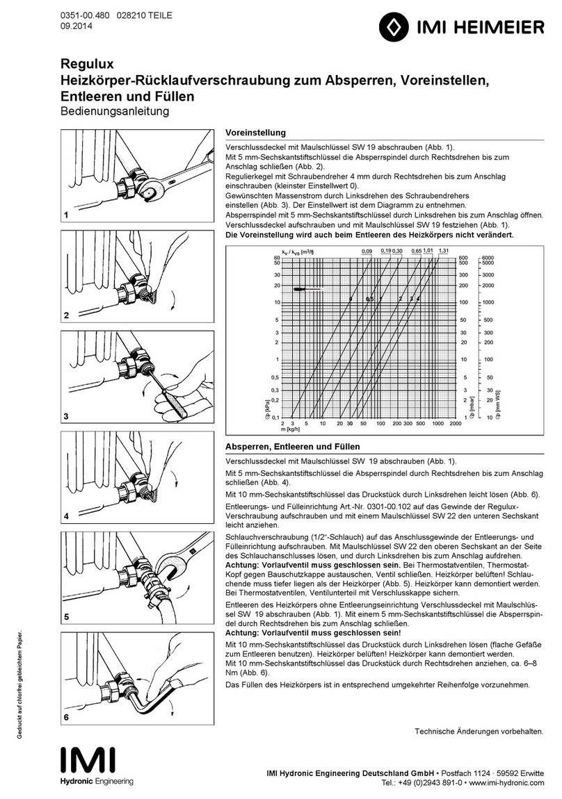
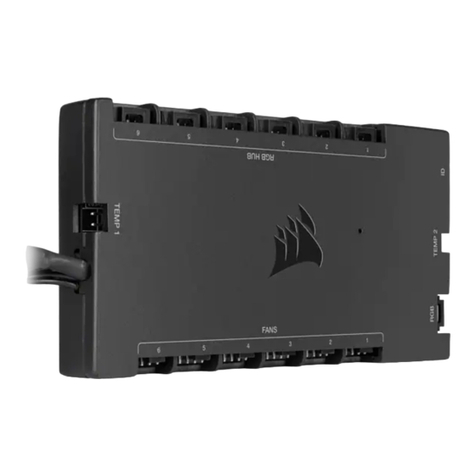
Imi Heimeier UH8-RF V2 User manual

1
UH8-RF V2

2

3
Table of contents/Inhaltsverzeichnis/Table des matières
EN
UH8-RF V2 – Installation manual ..................................................................4
Installation ....................................................................................................5
UH8-RF V2 wiring.........................................................................................6
Wiring diagram – UH8-RF V2 Direct pump connection..................................8
Wiring diagram – UH8-RF V2 with UFH and Radiator valves .......................10
System setup .............................................................................................12
System configuration ..................................................................................13
DE
UH8-RF V2 – Installationsanleitung .............................................................14
Installation ..................................................................................................15
Anschlussdiagramm UH8-RF V2 ................................................................16
Anschlussdiagramm – UH8-RF V2 Direkter Pumpenanschluss ...................18
Anschlussdiagramm – UH8-RF V2 mit FBH und Heizkörperventile ..................20
System einrichten .......................................................................................22
Konfiguration des Systems .........................................................................23
FR
UH8-RF V2 – Manuel d’installation..............................................................24
Installation ..................................................................................................25
Câblage UH8-RF V2...................................................................................26
Schéma de câblage – UH8-RF V2 Raccordement direct de la pompe........28
Schéma de câblage – UH8-RF V2 avec UFH et vanne de radiateur ............30
Configuration des réglages .........................................................................32
Configuration du circuit...............................................................................33
Notes/Notizen/Notes ..................................................................................34

4
UH8-RF V2 – Installation manual
Description
The UH8-RF V2 is an 8 Zone central wiring centre for use with
IMI Heimeier RF thermostats.
The UH8-RF V2 can be used to control any actuator or valve, which
requires a 230 VAC signal to open. For mid position valves and those
requiring a closing signal, a changeover relay is required. The UH8-
RF V2 also oers the ability to operate a boiler or other heat source
through a volt free output with changeover contacts, giving you both
a heat on signal and a heat o signal.
Additional outputs designed for use with hot water or underfloor
heating systems, are also included as standard. These are the pump
and valve outputs which would normally operate a manifold pump or
a manifold valve.
Any output which is not needed can be ignored.
Test switches are included for the installation engineer and further
options include creepage protection and pump delay.
Operation
Using the toggle switches, each channel used on this system can be
congured for either a radiator zone or underfloor heating zone.
When the thermostat sends a signal for heating, the UH8-RF V2
will provide a 230 VAC output on the paired zone and also bring on
the boiler/other heat source output. If the zone is congured as an
underfloor heating zone, the UH8-RF V2 will also start the pump and
valve outputs.
If an enable signal is received from a hot water time clock on the
system, only the H/W output will become active. This is a timed
output, which is normally fed to a cylinder thermostat, then to a valve,
but could also be used for towel rails. In either case the valve auxiliary
switch would operate the boiler/other heat source.
Other functions
Creepage
During hot weather the heating is not normally needed as often, this
means that valves and pumps that are not being used can seize and
refuse to operate. To prevent this, it is good practice to operate the
valve or pump once a day, the creepage function does this for you.
Once enabled the UH8-RF V2 will operate each valve or pump for 1
minute, if the outputs have not been operated by a thermostat, within
the preceding 24 hours. This function does not operate the boiler
output.
Pump delay
Some valves or actuators can take more than a minute to open, if
the boiler and pump operate before the valve is open it can force a
boiler to go to lockout and stop operating. This function delays the
operation of the pump and boiler to give the actuators and valves
time to open.

5
Installation
The UH8-RF V2 can be mounted directly to a wall using four screws or
alternatively, the unit can be DIN rail mounted.
When DIN Rail mounting, you first need to insert the two clips provided
on the back of the UH8-RF V2, as shown in the image;
• On the back of the UH8-RF V2, position the clip in the middle and
slide down.
• Points A and B locate in the corresponding holes and lock into place.
• Locate the UH8-RF V2 onto the DIN rail from the top.
• Pull the clip down and push the bottom of the UH8-RF V2 onto the
DIN rail.
• Releasing the clip will lock the UH8-RF V2 in place on the DIN rail.
To remove the UH8-RF V2, pull both clips down and remove from the
DIN rail.
Insert clip here.
Then slide down to lock in place.
A
B

6
UH8-RF V2 wiring
The UH8-RF V2 should be fitted as close as possible to the equipment it is controlling, but never within a metal enclosure, if this cannot be
avoided an extension antenna (EA1) must be fitted and placed outside the metal enclosure.
Connections
Mains supply
Power supply into the UH8-RF V2 which should be fused at 5A these
connections are marked;
L = live or phase 230 VAC 50/60Hz
N = neutral
E = earth
Heat/cool enable
This is the main call for heat for the system, there are 3 connections;
C = common
NO = normally open
NC = normally closed
Electrically this is a two-way switch, whatever supply is placed on the
C connection, is fed to the NC connection when there is no call for
heat. This is then switched to the NO connection when there is a call
for heat.
Most systems will use the common (C ) and normally open (NO)
connections.
Hot water
This output is used to control a hot water cylinder thermostat
C = common
NO = normally open
NC = normally closed
Electrically this is a two-way switch, whatever supply is placed on the
common connection, is fed to the NC connection when there is no
call for hot water. This is then switched to the NO connection when
there is a call for hot water.
Hot water continued
Normally the NO connection would be wired to the hot water cylinder
thermostat, then from there to the hot water valve, the valve auxiliary
switch will then start the boiler/other heat source.
Most systems will use the common and normally open connections.
Zones 1…8
Zones outputs are clearly marked;
L = live out to actuator or valve
N = neutral to actuator or valve
There are two connections live (L) and neutral (N), both terminals
marked L are the same and both terminals marked N are the same.
Each zone output is numbered, Zone 1 will respond to radio signals
from the thermostat paired to Zone 1. Zone 2 output will respond to
thermostat numbered 2 etc.
Manifold pump/valve
Used for an underoor heating manifold pump and or valve
Connections are clearly marked;
L = live
E = earth
N = neutral
When an underfloor heating zone sends a call for heat to the UH8-
RF V2, the live and neutral output will supply 230 V to the manifold
pump/valve. It is recommended that this is fed through a high limit
switch, placed on the heating manifold to protect against mechanical
failure of the manifolds temperature control.

7
Dew point sensor (cooling mode only)
Dew point sensing help to reduce the risk of condensation whilst
cooling is in demand.
When activated, the sensor sends a signal back to the UH8-RF V2,
and will shutdown cooling to the manifold. During this time, the dew
point indicator light will show.
Connections (24 VDC)
+ = Positive
- = Negative
SL = Input
Engineers test switches
These are a block of 12 dip switches, used to test each zone, boiler,
pump and HW outputs. To enable any output, put the switch in the
ON position. When installation is complete all switches MUST be in
the OFF position.
Record the rooms names connected to each zone with the zone
number and record the channel number you have selected, you will
need this information when installing the thermostats.
Fuses
5A, 20 mm anti-surge fuse, this fuse supplies power to all 230
V outputs from the board, it protects the zone, pump and valve
outputs.
Zones 1 to 8 buttons and indicators
Each Zone has an indicator light and button associated with it.
Light functions:
1. Light on when the zone output is on.
2. Light flashes when the zone is in pairing mode.
Button functions:
1. Single press to manually turn output On/O.
2. Hold down for 5 seconds to start pairing mode, (indicator
steady flash.)
3. Hold down for 15 seconds to delete pairing, (indicator rapid
flash)
System indicators
When lights are on:
1
ON DP
23456789101112
PUMP
ZONE1
ZONE2
ZONE3
ZONE4
ZONE5
ZONE6
ZONE7
ZONE8
H/W
HEAT
1. Dew point - Informs you that cooling has been
shut o to prevent condensation.
2. Hot water- Output is On.
3. Pump Output is On.
4. System is cooling.
5. System is heating.

8
Wiring key
Neutral
Earth
Live
End Switch/
Heat Enable
BOILER
LLNNLLNNLLNNENL ENL
FUSE 5A
Select Zone Switch Position to match your system
1. Radiator with Zone Valve end switch
2. Radiator with Actuators - enables heat output
3. UFH enables zone, manifold pump and heat output
ZONE 1ZONE 2ZONE 3
1 2 312 312 3
MAINS
SUPPLY
3A
UFH PUMP
LLNNLLNNLLNN
LL
NN
NO
CNC NO
CNC SL+-
1
AU
X
ENABLE CREEPAGE
HEAT ENABLE 1
DELAY (MINS)
2
ON DP
234
ZONE
5ZONE 6ZONE 7ZONE 8
1 2
312 312 312 3
CONNECTOR
TIME
CLOCK
HOT WATER
VALVE
LLNN
ZONE 4
1 2 3
230 V ACTUA
TORS
HOT WATERHEAT
PUMP
MAINS IN
RT1-
+SL
Dew point sensor
Flow sensor
DEW POINT
1
ON DP
23456789101112
PUMP
ZONE1
ZONE2
ZONE3
ZONE4
ZONE5
ZONE6
ZONE7
ZONE8
H/W
HEAT
ZONE 8
ZONE 7
ZONE 1ZONE 2ZONE
3Z
ONE
5ZONE 6
ZONE 4
Front panel connection
Wiring diagram – UH8-RF V2 Direct pump connection

9
Wiring key
Neutral
Earth
Live
End Switch/
Heat Enable
BOILER
LLNNLLNNLLNNENL ENL
FUSE 5A
Select Zone Switch Position to match your system
1. Radiator with Zone Valve end switch
2. Radiator with Actuators - enables heat output
3. UFH enables zone, manifold pump and heat output
ZONE 1ZONE 2ZONE 3
1 2 312 312 3
MAINS
SUPPLY
3A
UFH PUMP
LLNNLLNNLLNN
LLNN
NO
CNC NO
CNC SL+-
1
AUX
ENABLE CREEPAGE
HEAT ENABLE 1
DELAY (MINS) 2
ON DP
234
ZONE 5Z
ONE 6ZONE 7ZONE 8
1 2 31
2 312 312 3
CONNECTOR
TIME
CLOCK
HOT WATER
VALVE
LLNN
ZONE 4
1 2 3
230 V ACTUATO
RS
HOT WATERHEAT
PUMP
MAINS IN
RT1-
+SL
Dew point sensor
Flow sensor
DEW POINT
1
ON DP
23456789101112
PUMP
ZONE1
ZONE2
ZONE3
ZONE4
ZONE5
ZONE6
ZONE7
ZONE8
H/W
HEAT
ZONE 8
ZONE 7
ZONE 1ZONE 2ZONE 3ZONE 5Z
ONE 6
ZONE 4
Front panel connection
Recommended cable for Dew point sensor:
Multi-core screened.
Not to exceed 20 meters
in cable length!
Ratings
Supply 230 VAC, 50 Hz
Power consumption 7W
Max. load on boiler output 3A 230 VAC resistive
Max. load on H/W output 3A 230 VAC resistive
Max. load on zone outputs 3A 230 VAC resistive
Max. total load 5A
Optional accessories
Boost (Repeater)
Extension antenna (included) (EA1)

10
Wiring diagram – UH8-RF V2 with UFH and Radiator valves
Wiring key
Neutral
Earth
Live
End switch/
Heat Enable
BOILER
LLNNLLNNLLNNEN L EN L
FUSE 5A
Select Zone Switch Position to match your system
1. Radiator with Zone Valve end switch
2. Radiator with Actuators - enables heat output
3. UFH enables zone, manifold pump and heat output
ZONE 1ZONE 2ZONE 3
1 2 312 312 3
MAINS
SUPPLY
3A
UFH PUMP
LLNNLLNNLLNN
LL
NN
NO
CNC NO
CNC SL+-
1
AUX
ENABLE CREEPAGE
HEAT ENABLE 1
DELAY (MINS) 2
ON DP
234
ZONE
5ZONE 6ZONE 7ZONE 8
1 2
312 312 312 3
CONNECTOR
HOT WATER
VALVE
LLNN
ZONE 4
1 2 3
230 V ACTUATO
RS
HOT WATERHEAT
MAINS IN
RT1-
+SL
Dew point sensor
Flow sensor
DEW POINT
1
ON DP
23456789101112
PUMP
ZONE1
ZONE2
ZONE3
ZONE4
ZONE5
ZONE6
ZONE7
ZONE8
H/W
HEAT
ZONE 7
ZONE 1ZONE 2 ZONE
3Z
ONE
5ZONE 6
ZONE 4
RADIATOR
VALVE
UFH VALVE
PUMP
TIME
CLOCK
ZONE 8
Front panel connection

11
Wiring key
Neutral
Earth
Live
End switch/
Heat Enable
BOILER
LLNNLLNNLLNNEN L EN L
FUSE 5A
Select Zone Switch Position to match your system
1. Radiator with Zone Valve end switch
2. Radiator with Actuators - enables heat output
3. UFH enables zone, manifold pump and heat output
ZONE 1ZONE 2ZONE 3
1 2 312 312 3
MAINS
SUPPLY
3A
UFH PUMP
LLNNLLNNLLNN
LLNN
NO
CNC NO
CNC SL+-
1
AUX
ENABLE CREEPAGE
HEAT ENABLE 1
DELAY (MINS) 2
ON DP
234
ZONE 5Z
ONE 6ZONE 7ZONE 8
1 2 31
2 312 312 3
CONNECTOR
HOT WATER
VALVE
LLNN
ZONE 4
1 2 3
230 V ACTUATORS
HOT WATERHEAT
MAINS IN
RT1-
+SL
Dew point sensor
Flow sensor
DEW POINT
1
ON DP
23456789101112
PUMP
ZONE1
ZONE2
ZONE3
ZONE4
ZONE5
ZONE6
ZONE7
ZONE8
H/W
HEAT
ZONE 7
ZONE 1ZONE 2 ZONE 3ZONE 5Z
ONE 6
ZONE 4
RADIATOR
VALVE
UFH VALVE
PUMP
TIME
CLOCK
ZONE 8
Front panel connection
Recommended cable for Dew point sensor:
Multi-core screened.
Not to exceed 20 meters
in cable length!
Ratings
Supply 230 VAC, 50 Hz
Power consumption 7W
Max. load on boiler output 3A 230 VAC resistive
Max. load on H/W output 3A 230 VAC resistive
Max. load on zone outputs 3A 230 VAC resistive
Max. total load 5A
Optional accessories
Boost (Repeater)
Extension antenna (included) (EA1)

12
System setup
Zone type toggle switches
There is a 3 position toggle switch above each zone. This switch
allows 3 dierent switched outputs when the thermostat demands
heat.
Position 1 - Zone output only
When a thermostat is in demand, the UH8-RF V2 will
activate the Zone output to actuators only, PUMP and
HEAT outputs will remain o.
Position 2 - Zone output with heat demand
When a thermostat is in demand the UH8-RF V2 will
activate the zone output to the actuators and heat
demand to the boiler.
Position 3 - Zone output with heat demand and
manifold pump
When a thermostat is in demand, the UH8-RF V2 will
activate the zone output to the actuators, the heat
demand to the boiler and the manifold pump.
DIP switches
There is a 4 way dip switch responsible for 3 functions;
1. Aux
2. Enable Creepage
3. Heat Enable Delay 1 minute.
4. Heat Enable Delay 2 minutes.
In normal use these DIP switches can be ignored and should be left
in the o position.
Heat enable delay, dip switches 1 and 2
Switch 2 ON, Switch 1 OFF = Will delay the heat output for 1 minute.
Switch 2 OFF, Switch 1 ON = Will delay the heat output for 2 minutes.
Switch 2 ON, Switch 1 ON = Will delay the heat output for 3 minutes.
Creepage protection, dip switch 3
To enable creepage protection, put switch 3 to the ON position.
ZONE 1
1 2 3
ZONE 1
1 2 3
ZONE 1
1 2 3
1
ENABLE CREEPAGE
HEAT ENABLE
1
DELAY (MINS) 2
ON DIP
234
AUX

13
System configuration
In use Zone type Zone title
Underfloor Radiator
Zone 1
Zone 2
Zone 3
Zone 4
Zone 5
Zone 6
Zone 7
Zone 8
Hot water
UH8-RF V2 Title:..............................................................................................
PLEASE COMPLETE DURING INSTALLATION

14
UH8-RF V2 – Installationsanleitung
Beschreibung
Die UH8-RF V2 ist eine 8-Zonen-Klemmleiste für die Verwendung mit
den IMI Heimeier RF-Thermostaten.
UH8-RF kann zur Ansteuerung aller 230-V AC Stellantriebe oder
Ventile verwendet werden. Für Mittelstellungsventile und solche,
die ein Schließsignal benötigen, ist ein Umschaltrelais erforderlich.
Die UH8-RF V2 bietet auch die Möglichkeit, einen Heizkessel oder
eine andere Wärmequelle über einen potenzialfreien Ausgang mit
Wechselkontakten ein- oder ausschalten.
Zusätzliche Ausgänge für Pumpen und Ventile zur Steuerung der
Verteilerpumpe oder eines Verteilerventil gehören ebenfalls zur
Standardausstattung.
Unbelegte Zonen müssen nicht zusätzlich verdrahtet werden.
Für Installateure gibt es zusätzlich Prüfausgänge zur manuellen
Aktivierung der Ausgänge, als auch die Option von Pumpenschutz
und Pumpverzögerung.
Im Betrieb
Mit den Kippschaltern kann jeder Kanal dieses Systems entweder für
eine Heizkörperzone oder eine Fußbodenheizungszone konfiguriert
werden.
Wenn der Thermostat ein Signal zum Heizen sendet, wird die
Spannungsversorgung von 230-V AC von der UH8-RF V2 an die
Stellantriebe der jeweiligen Zone freigeschaltet. Optional kann
auch der Wärmeerzeuger einschaltet werden. Wenn die Zone als
Fußbodenheizungszone konfiguriert ist, schaltet die UH8-RF V2 auch
die Pumpen- und Ventilausgänge ein.
Weitere Funktionen
Pumpenschutzfunktion
Diese Funktion hilft zu vermeiden, dass sich Pumpen oder Ventile
durch die geringe Nutzung, außerhalb der Heizsaison zusetzen und
beschädigt werden.
Es ist es ratsam, das Ventil oder die Pumpe einmal am Tag zu
betätigen und ein zusetzen zu umgehen; die Pumpenschutzfunktion
übernimmt dies für Sie.
Nach der Aktivierung dieser Funktion, schaltet die UH8-RF V2 jedes
Ventil oder jede Pumpe für 1 Minute ein, wenn die Ausgänge in den
vorangegangenen 24 Stunden nicht von einem Thermostat gesteuert
wurden. Diese Funktion steuert nicht den Kesselausgang.
Pumpenverzögerungsfunktion
Wenn der Kessel und die Pumpe in Betrieb sind, bevor das Ventil
geönet ist, kann dies dazu führen, dass der Kessel gesperrt wird
und nicht mehr funktioniert. Die Pumpenverzögerungsfunktion
verzögert den Betrieb von Pumpe und Kessel, um den Stellantrieben
und Ventilen Zeit zum Önen zu geben.

15
Installation
Die UH8-RF V2 kann mit vier Schrauben direkt an der Wand befestigt
werden. Alternativ kann das Gerät auch auf einer Hutschiene montiert
werden.
Bei der Montage auf einer Hutschiene müssen Sie zunächst die beiden
mitgelieferten Clips auf der Rückseite der UH8-RF V2 einsetzen, wie in
der Abbildung gezeigt;
• Positionieren Sie den Clip auf der Rückseite der UH8-RF V2 in der
Mitte und schieben Sie ihn nach unten.
• Die Punkte A und B werden in die entsprechenden Löcher gesteckt
und eingerastet.
• Setzen Sie die UH8-RF V2 von oben auf die DIN-Schiene.
• Ziehen Sie den Clip nach unten und schieben Sie die Unterseite der
UH8-RF V2 auf die DIN-Schiene.
• Durch Lösen des Clips wird die UH8-RF V2 auf der DIN-Schiene
arretiert.
Um die UH8-RF V2 zu entfernen, ziehen Sie beide Klammern nach
unten und nehmen diese von der DIN-Schiene ab.
Clip hier einfügen.
Schieben Sie sie dann nach unten, um sie
zu verriegeln.
A
B

16
Anschlussdiagramm UH8-RF V2
Die UH8-RF V2 sollte so nah wie möglich an dem zu steuernden Gerät angebracht werden, jedoch niemals innerhalb eines Metallgehäuses. Wenn
dies nicht vermieden werden kann, muss eine Verlängerungsantenne (EA1) angebracht und außerhalb des Metallgehäuses platziert werden.
Verbindungen
Netzanschluss
Die Spannungsversorgung zur UH8-RF V2 muss mit 5A abgesichert
sein.
Die Anschlüsse zu Spannungsversorgung der UH8-RF V2 sind wie
folgt gekennzeichnet;
L = Spannung / Phase 230 VAC 50/60Hz
N = Nullleiter
E = Erde
Heizen/Kühlen aktivieren
Dies ist die Hauptwärmequelle für das System, es gibt 3 Anschlüsse;
C = COM (gemeinsamer Anschluss)
NO = Stromlos oen
NC = Stromlos geschlossen
Elektrisch gesehen handelt es sich um einen Wechselschalter: Wenn
Wärmebedarf besteht wird der NO-Kontakt geschlossen und der
NC-Kontakt geönet.
In den meisten Systemen werden der COM-Anschluss (C) und die
Stromlos oenen (NO) Anschlüsse verwendet.
Warmwasser
Dieser Ausgang wird zur Steuerung eines Warmwasserspeicher-
thermostats verwendet
C = COM (gemeinsamer Anschluss)
NO = Stromlos oen
NC = Stromlos geschlossen
Elektrisch gesehen handelt es sich um einen Wechselschalter: Wenn
Bedarf an Warmwasser besteht wird der NO-Kontakt geschlossen
und der NC-Kontakt geönet.
Normalerweise wird der NO-Anschluss (stromlos geönet) mit dem
Thermostat des Warmwasserspeichers und von dort aus mit dem
Warmwasserventil verbunden; der Hilfsschalter des Ventils schaltet
dann den Heizkessel oder eine andere Wärmequelle ein.
In den meisten Systemen werden der COM-Anschluss (C) und die
Stromlos oenen (NO) Anschlüsse verwendet.
Zonen 1 bis 8
Die Zonenausgänge sind deutlich gekennzeichnet;
L = Stromausgang zum Stellantrieb oder Ventil
N = Nullleiter zum Stellantrieb oder Ventil
Es gibt zwei Anschlüsse, den stromführenden (L) und den neutralen
(N), wobei die beiden mit L gekennzeichneten Klemmen gleich sind
und die beiden mit N gekennzeichneten Klemmen gleich sind.
Jeder Zonenausgang ist nummeriert. Zone 1 reagiert auf Funksignale
des mit Zone 1 gekoppelten Thermostats. Der Ausgang der Zone 2
reagiert auf den Thermostat mit der Nummer 2 usw.
Heizkreisverteiler Pumpe/Ventil (Stellantrieb)
Wird für Ventile (Stellantriebe) und/oder Fußbodenheizungsverteiler-
Pumpen verwendet..
Die Anschlüsse sind wie folgt gekennzeichnet;
L = Phase
E = Erde
N = Nullleiter
Wenn eine Fußbodenheizungszone ein Heizsignal an die UH8-
RF V2 sendet, versorgt die Phase und der Nullleiter Ausgang die
Verteilerpumpe/das Ventil (Stellantrieb) mit 230 V. Es wird empfohlen,
dass diese über einen oberen Grenzwertschalter am Heizungsverteiler
gespeist wird, um einen mechanischen Ausfall der Temperaturregelung
des Verteilers zu verhindern.

17
Taupunktsensor (nur Kühlbetrieb)
Die Taupunktüberwachung hilft, das Risiko von Kondensation
während des Kühlbetriebs zu verringern.
Wenn der Sensor aktiviert wird, sendet er ein Signal an die UH8-RF
V2 und schaltet die Kühlung des Verteilers ab. Während dieser Zeit
leuchtet die Taupunktanzeige auf.
Anschlüsse (24 VDC)
+ = Positiv
- = Negativ
SL = Eingang
Funktionsprüfschalter
Dies ist ein Block von 12 DIP-Schaltern, die zum Testen der einzelnen
Zonen-, Kessel-, Pumpen- und HW-Ausgänge verwendet werden.
Um einen Ausgang zu aktivieren, stellen Sie den Schalter in die
Position ON (Ein). Wenn die Installation abgeschlossen ist, MÜSSEN
alle Schalter in der Position OFF (Aus) stehen.
Notieren Sie die Namen der Räume, die mit jeder Zone verbunden
sind, sowie die Zonennummer, und notieren Sie die von Ihnen
gewählte Kanalnummer.
Sicherungen
5A, 20 mm Schmelzsicherung, diese Sicherung versorgt alle 230 V
Ausgänge der Platine, sie schützt die Zonen-, Pumpen- und
Ventilausgänge.
Tasten und Anzeigen in den Zonen 1 bis 8
Jede Zone verfügt über eine Kontrollleuchte und eine Taste, die ihr
zugeordnet ist.
LED-Funktionen:
1. Leuchtet, wenn der Zonenausgang eingeschaltet ist.
2. Die LED blinkt, wenn sich die Zone im Kopplungsmodus
befindet.
Funktionen der Tasten:
1. Einmaliges Drücken schaltet den Ausgang manuell ein/aus
2. Halten Sie die Taste 5 Sekunden lang gedrückt, um den
Kopplungsmodus zu starten (die Anzeige blinkt ständig).
3. 15 Sekunden lang gedrückt halten, um die Kopplung zu löschen
(Anzeige blinkt schnell)
System-Indikatoren
Wenn das Licht eingeschaltet ist:
1
ON DP
23456789101112
PUMP
ZONE1
ZONE2
ZONE3
ZONE4
ZONE5
ZONE6
ZONE7
ZONE8
H/W
HEAT
1. Taupunkt - Informiert Sie darüber, dass die Kühlung
abgeschaltet wurde, um Kondensation zu vermeiden.
2. Warmwasser - Ausgang ist eingeschaltet.
3. Der Pumpenausgang ist eingeschaltet.
4. Das System kühlt.
5. Das System heizt.

18
Legende
Neutralleiter
Erde
Phase
Endschalter/
Heizungsfreigabe
Kessel
LLNNLLNNLLNNENL ENL
Sicherung 5A
Select Zone Switch Position to match your system
1. Radiator with Zone Valve end switch
2. Radiator with Actuators - enables heat output
3. UFH enables zone, manifold pump and heat output
ZONE 1ZONE 2ZONE 3
1 2 312 312 3
Netzver-
sorgung
3A
FBH-Pumpe
LLNNLLNNLLNN
LL
NN
NO
CNC NO
CNC SL+-
1
AU
X
ENABLE CREEPAGE
HEAT ENABLE 1
DELAY (MINS) 2
ON DP
234
ZONE
5ZONE 6ZONE 7ZONE 8
1 2
312 312 312 3
Stecker
(für Abdeckhaube)
Zeitschalt-
uhr
Warmwasser-
ventil
LLNN
ZONE 4
1 2 3
230V
-Stellantriebe
Warmwasser-
versorgung
Heizen
Pumpe
Spannungsversorgung
RT1-
+SL
Taupunktsensor
Durchfluss-
sensor
Taupunktsensor-
anschluss
1
ON DP
23456789101112
PUMP
ZONE1
ZONE2
ZONE3
ZONE4
ZONE5
ZONE6
ZONE7
ZONE8
H/W
HEAT
ZONE 8
ZONE 7
ZONE 1ZONE 2ZONE
3Z
ONE
5ZONE 6
ZONE 4
Anschlussplatine
Anschlussdiagramm – UH8-RF V2 Direkter Pumpenanschluss

19
Legende
Neutralleiter
Erde
Phase
Endschalter/
Heizungsfreigabe
Kessel
LLNNLLNNLLNNENL ENL
Sicherung 5A
Select Zone Switch Position to match your system
1. Radiator with Zone Valve end switch
2. Radiator with Actuators - enables heat output
3. UFH enables zone, manifold pump and heat output
ZONE 1ZONE 2ZONE 3
1 2 312 312 3
Netzver-
sorgung
3A
FBH-Pumpe
LLNNLLNNLLNN
LLNN
NO
CNC NO
CNC SL+-
1
AUX
ENABLE CREEPAGE
HEAT ENABLE 1
DELAY (MINS) 2
ON DP
234
ZONE 5Z
ONE 6ZONE 7ZONE 8
1 2 31
2 312 312 3
Stecker
(für Abdeckhaube)
Zeitschalt-
uhr
Warmwasser-
ventil
LLNN
ZONE 4
1 2 3
230V-Stellantrieb
e
Warmwasser-
versorgung
Heizen
Pumpe
Spannungsversorgung
RT1-
+SL
Taupunktsensor
Durchfluss-
sensor
Taupunktsensor-
anschluss
1
ON DP
23456789101112
PUMP
ZONE1
ZONE2
ZONE3
ZONE4
ZONE5
ZONE6
ZONE7
ZONE8
H/W
HEAT
ZONE 8
ZONE 7
ZONE 1ZONE 2ZONE 3ZONE 5Z
ONE 6
ZONE 4
Anschlussplatine
Empfohlenes Kabel für Taupunktsensor:
Mehradrig abgeschirmt.
Die Kabellänge darf 20 Meter
nicht überschreiten!
Maximalwerte
Spannungsversorgung 230 VAC, 50 Hz
Leistungsaufnahme 7W
Max. Last am Kesselausgang 3A 230 VAC ohmsche Last
Max. Last am Warmwasserausgang 3A 230 VAC ohmsche Last
Max. Last der Zonenausgänge 3A 230 VAC ohmsche Last
Max. Gesamtlast 5A
Optionales Zubehör
Boost (Verstärker)
Antennenverlängerung (im
Lieferumfang enthalten)
(EA1)

20
Legende
Neutralleiter
Erde
Phase
Endschalter/
Heizungsfreigabe
Kessel
LLNNLLNNLLNNEN L EN L
Sicherung 5A
Select Zone Switch Position to match your system
1. Radiator with Zone Valve end switch
2. Radiator with Actuators - enables heat output
3. UFH enables zone, manifold pump and heat output
ZONE 1ZONE 2ZONE 3
1 2 312 312 3
Netzver-
sorgung
3A
FBH-Pumpe
LLNNLLNNLLNN
LL
NN
NO
CNC NO
CNC SL+-
1
AUX
ENABLE CREEPAGE
HEAT ENABLE 1
DELAY (MINS) 2
ON DP
234
ZONE
5ZONE 6ZONE 7ZONE 8
1 2
312 312 312 3
Stecker
(für Abdeckhaube)
Warmwasser-
ventil
LLNN
ZONE 4
1 2 3
230V-Stellantrieb
e
Warmwasser-
versorgung
Heizen
Spannungsversorgung
RT1-
+SL
Taupunktsensor
Durchfluss-
sensor
Taupunktsensor-
anschluss
1
ON DP
23456789101112
PUMP
ZONE1
ZONE2
ZONE3
ZONE4
ZONE5
ZONE6
ZONE7
ZONE8
H/W
HEAT
ZONE 7
ZONE 1ZONE 2 ZONE
3Z
ONE
5ZONE 6
ZONE 4
Heizkörper-
ventil
FBH-Ventil
Pumpe
Zeitschalt-
uhr
ZONE 8
Anschlussplatine
Anschlussdiagramm – UH8-RF V2 mit FBH und Heizkörperventile
Table of contents
Languages:
Other Imi Heimeier Controllers manuals
