IMI NORGREN 54D User manual

Operation manual
54D-xxxxx-DD0-xx 2 x PNP
Electronic
Pressure Sensor
54D
2
Electronic Pressure Sensor 54D
Operation manual
7503761000000050 05/2019
Content
1. Preliminary note 4
1.1 Symbols used 4
2 Safety information 4
3. Functions and features 4
4. Function 5
4.1 Processing of the measured signals 5
4.2 Switching function 5
4.3 Diagnostic function 6
5. Installation 6
5.1 Mounting accessories 6
5.2 DIN rail mounting 7
5.3 Panel mounting 7
6 Electrical connection 8
7. Operating and display elements 9
8. Menu 10
8.1 Menu structure 10
8.2 Explanation of the menu 11
9. Parameter setting 12
9.1 Parameter setting in general 12
9.2 Set output signals 14
9.2.1 Set the unit of measurement for system pressure 14
9.2.2 Set the output function 14
9.2.3 Set the switching limits (hysteresis function) 14
9.2.4 Set the switching limits (window function) 14
9.3 User settings (optional) 14
9.3.1 Set delay for the switching outputs 14
9.3.2 Set damping for the switching outputs 15
9.3.3 Configuration of the display 15
9.3.4 Zero-point calibration 16

3
Electronic Pressure Sensor 54D
Operation manual
7503761000000050 05/2019
9.4 Service functions 17
9.4.1 Read min/max values for the system pressure 17
9.4.2 Reset all parameters to factory setting 17
10. Operation 17
10.1 Read set parameters 17
10.2 Error indications 17
10.3 Setting ranges 18
11. Factory setting 18

4
Electronic Pressure Sensor 54D
Operation manual
7503761000000050 05/2019
1. Preliminary note
1.1 Symbols used
►Instructions
> Reaction, result
[…] Designation of keys, buttons or indications
→Cross-reference
Important note
Non-compliance can result in malfunction or interference.
2. Safety instructions
Please read this document prior to set-up of the unit. Ensure that the product is suitable for your
application without any restrictions.
If the operating instructions or the technical data are not adhered to, personal injury and/or
damage to property can occur.
Check the compatibility of the product materials with the media to be measured in all
applications.).
3. Functions and features
The unit monitors the system pressure/differential pressure in compressed air networks and
pneumatic systems of machines and plants.
Avoid static and dynamic overpressure exceeding the specified overload pressure by taking
appropriate measures.
The indicated bursting pressure must not be exceeded.
Even if the bursting pressure is exceeded only for a short time, the unit may be destroyed.
ATTENTION: Risk of injury!
Pressure Equipment Directive (PED): The units comply with section 3, article (3) of the
Directive 97/23/EC and are designed and manufactured for media of fluid group 2 (stable
gases and non-superheated liquids) in accordance with the sound engineering practice.
Type of pressure: relative pressure
Order number Measuring range Permissible
overpressure
Bursting pressure
bar
PSI
bar
PSI
bar
PSI
54D-V101…
-1…1
-14,5 …14,5
20
290
30
435
54D-V110…
-1 …10
-14,5 …145
20
290
30
435
5
Electronic Pressure Sensor 54D
Operation manual
7503761000000050 05/2019
4. Function
4.1 Processing of the measured signals
The unit displays the current system pressure.
It generates 2 output signals according to the parameter setting.
OUT1 Switching signal for limit value
OUT2 2 options
• Switching signal for system pressure limit value.
• Diagnostic signal (output 1 is inactive in case of a fault).
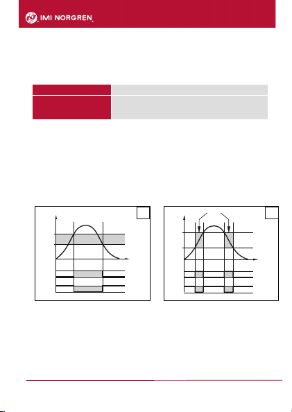
4.2 Switching function
OUT1 changes its switching state if it is above or below the set switching limits (SP1, rP1). The
following switching functions can be selected:
Hysteresis function / normally open: [ou1] = [Hno] (→ fig. 1)
Hysteresis function / normally closed: [ou1] = [Hnc] (→ fig. 1)
First the set point (SP1) is set, then the reset point (rP1) with the requested difference.
Window function / normally open: [ou1] = [Fno] (→ fig. 2).
Window function / normally closed: [ou1] = [Fnc] (→ fig. 2).
The width of the window can be set by means of the difference between FH1 and FL1. FH1 =
upper value, FL1 = lower value.
P = system pressure / differential pressure; HY = hysteresis; FE = window
t
SP
rP
1
0
1
Hno
Hnc
HY
t
P
FH
FL
1
0
1
0
FE
Fno
Fnc
1
2
6
Electronic Pressure Sensor 54D
Operation manual
7503761000000050 05/2019
4.3 Diagnostic function
Output 2 is used as diagnostic output based on the DESINA specification if [ou2] = [diA].
If there is no fault, the output is switched and carries Ub+ .
In case of malfunctions in the following areas, the output is inactive:
oshort circuit in output 1.
oEPROM function.
oRAM function.
oparameter setting.
oprocessor function.
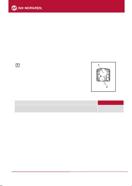
5. Installation
Before installing and removing the unit: Make sure that no
pressure is applied to the system.
►Screw the pressure connection or adapter G1/8 to the main
pressure connection (1) and tighten:
Maximum tightening torque: 8 Nm.
Maximum thread length: 7.5mm
►If required: Screw the pressure connection or adapter M5 to the
auxiliary pressure connection (2) and slightly tighten to avoid
damage to the thread:
Maximum tightening torque: 2.5 Nm.
Maximum thread length: 7.5mm
5.1 Mounting accessories
The following components can be supplied as accessories: Order no.
Mounting set for DIN rail mounting
(DIN rail TH 35-7.5 to EN 60715)
54D-DINRAIL-CLIP

7
Electronic Pressure Sensor 54D
Operation manual
7503761000000050 05/2019
5.2 DIN rail mounting
DIN rail TH 35-7.5 to EN 60715
►Fix the mounting clip (1) with the M4 x 35 screws (2) to the flange.
Maximum tightening torque: 0,5 Nm.
►Hook the unit into the DIN rail and clip it into place.
Removal:
►Lever out the mounting clip with a screwdriver at the top or at the bottom and remove the unit.
5.3 Panel mounting
►Fix the unit with 2 M4 x 35 screws (1) (not included) to the rear panel. Maximum tightening
torque: 0.5 Nm.
20
20
8
Electronic Pressure Sensor 54D
Operation manual
7503761000000050 05/2019
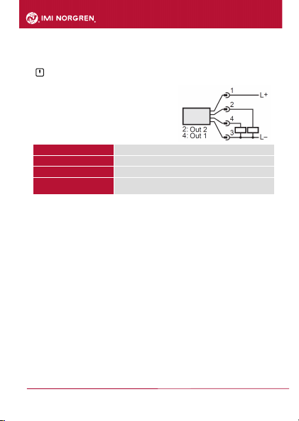
6. Electrical connection
The unit must be connected by a qualified electrician.
The national and international regulations for the installation of electrical equipment must be
adhered to.
Voltage supply according to EN 50178, SELV, PELV.
►Disconnect power.
►Connect the unit as follows:
Pin 1 Ub+
Pin 3 Ub-
Pin 4 (OUT1) Binary switching output pressure monitoring
Pin 2 (OUT2) • binary switching output if [ou2] = [Hno], [Hnc], [Fno] or [Fnc]
• diagnostic output if [ou2] = [diA]
9
Electronic Pressure Sensor 54D
Operation manual
7503761000000050 05/2019
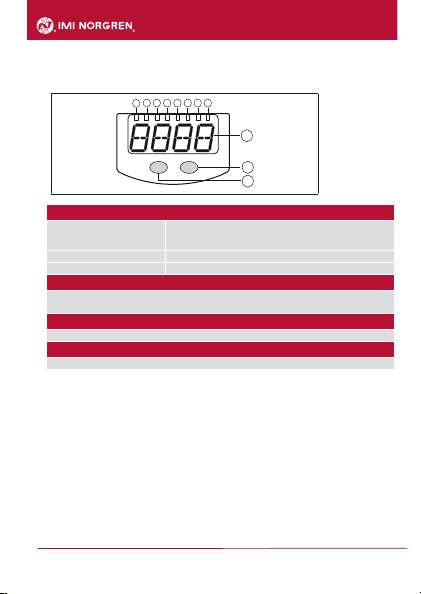
7. Operating and display elements
1 to 8: Indicator LEDs
LED 1 to LED 4 system pressure / differential pressure in the unit of
measurement
which is indicated on the label.
LEDs 5, 6
not used.
LED 7, 8
switching status of the corresponding output
9: Alphanumeric display, 4 digits
Display of the current system pressure.
Indication of the parameters and parameter values.
10: Set button
Setting of the parameter values (scrolling by holding pressed; incrementally by pressing once)
11: Mode/Enter button
Selection of the parameters and acknowledgement of the parameter values.
1
2
3
4
5
6
7
8
10
9
11
Mode/Enter
Set
10
Electronic Pressure Sensor 54D
Operation manual
7503761000000050 05/2019
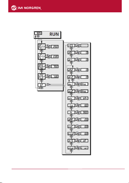
8. Menu
8.1 Menu structure
11
Electronic Pressure Sensor 54D
Operation manual
7503761000000050 05/2019
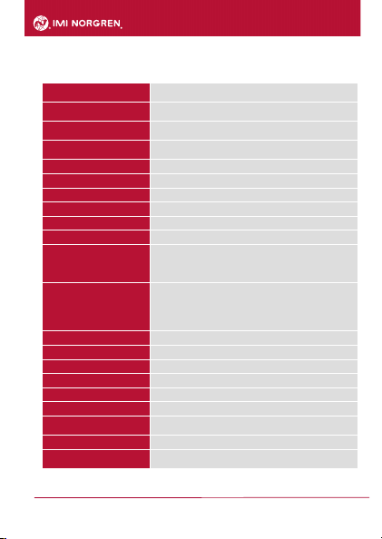
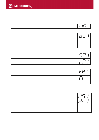
8.2 Explanation of the menu
SP1/rP1 Upper / lower limit value for system pressure at which OUT1
switches.
FH1/FL1 Upper / lower limit for the acceptable range (monitored by
OUT1).
SP2/rP2 Upper / lower limit value for system pressure at which OUT2
switches.
FH2/FL2 Upper / lower limit for the acceptable range (monitored by
OUT2).
EF Extended functions / opening of menu level 2.
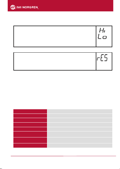
rES Restore factory setting.
dS1 Time delay for SP1 / FH1.
dS2 Time delay for SP2 / FH2.
dr1 Time delay for rP1 / FL1
dr2 Time delay for rP2 / FL2
ou1 Output function for OUT1:
Switching signal for the pressure limit values: hysteresis
function [H ..] or window function [F ..], either normally open [.
no] or normally closed [. nc].
ou2 Output function for OUT2:
• Switching signal for the pressure limit values: hysteresis
function [H ..] or window function [F ..], either normally open [.
no] or normally closed [. nc].
• Diagnostic signal [ou2] = diA.
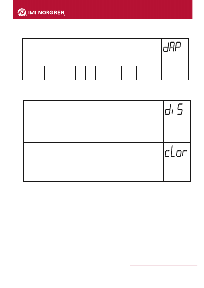
uni Standard unit of measurement for system pressure.
Lo Minimum value memory for system pressure.
Hi Maximum value memory for system pressure.
dAP Damping for the switching outputs.
coF Manually enter the zero point calibration.
tcoF Teach zero-point calibration.
SySP Setting of the system pressure for optimised differential
pressure measurement.
diS Update rate and orientation of the display.
cLor Colour of the digital display (permanent or alternating with
switching status OUT1).

12
Electronic Pressure Sensor 54D
Operation manual
7503761000000050 05/2019
9. Parameter setting
During parameter setting the unit remains in the operating mode. It continues to monitor with the
existing parameters until the parameter setting has been completed.
9.1 Parameter setting in general
Each parameter setting requires 3 steps:
If [C.Loc] is displayed when an attempt is made to modify a parameter value, parameters are
read or written via the IO-Link interface (temporary locking).
If [SLoc] is displayed when an attempt is made to modify a parameter value, the sensor is
locked via software. This locking cannot be removed on the sensor but unlocking has to be
made via the IO-Link interface.
1
2
3
Select parameter
►Press [Mode/Enter] until the requested
parameter is displayed.
Set parameter value
►Press [Set] and keep it pressed.
> Current setting value of the parameter
flashes for 5 s.
> After 5 s: setting value is changed:
incrementally by pressing the button once
or continuously by keeping the button
Numerical values are incremented continuously. For reducing the value: let the display
move to the maximum setting value. Then the cycle starts again at the minimum setting
value.
Acknowledge parameter value
►Briefly press [Mode/Enter].
> The parameter is displayed again.
The new setting value is saved.
Mode/Enter Set
Mode/Enter Set
Mode/Enter Set
Set other parameters:
Start again with step 1.
Finish parameter setting:
►Press [Mode/Enter] several times until the current measured value is displayed or wait for 15 s.
> The unit exits the parameter setting mode.
13
Electronic Pressure Sensor 54D
Operation manual
7503761000000050 05/2019
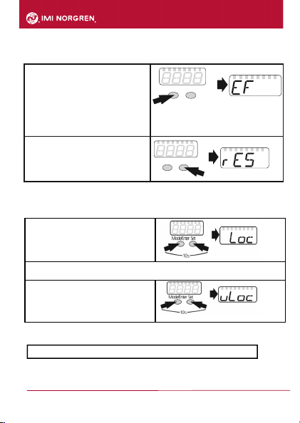
Change from menu level 1 to menu level 2:
Locking / unlocking
The unit can be locked electronically to prevent unintentional settings. Locking is also possible via
an IO-Link capable parameter setting tool.
►Make sure that the unit is in the normal
operating mode.
►Press [Mode/Enter] + [Set] for 10 s.
> [Loc] is displayed.
During operation: [Loc] is displayed for 15 s if you try to change parameter values.
For unlocking:
►Press [Mode/Enter] + [Set] for 10 s.
> [uLoc] is displayed.
On delivery: not locked.
Timeout:
► Press [Mode/Enter] until [EF] is displayed..
If the submenu is protected with an access code,
[cod1] is displayed.
►
Press [Set] and keep it pressed until the valid
code no. is displayed.
►
Briefly press [Mode/Enter].
When delivered by ifm electronic:
no access restriction.
►
Briefly press [Set].
> The first parameter of the submenu is displayed
(here: [rES])
Mode/Enter Set
Mode/Enter Set
If during parameter setting no pushbutton is pressed for 15 s, the unit exits the parameter
14
Electronic Pressure Sensor 54D
Operation manual
7503761000000050 05/2019
9.2 Set output signals
9.2.1 Set the unit of measurement for system pressure
►Select [Uni] and set the unit of measurement: [bAr], [kPa], [PSi], [inHg]
9.2.2 Set the output function
►Select [OU1] and set the function:
[Hno] = hysteresis function/NO,
[Hnc] = hysteresis function/NC,
[Fno] = window function/NO,
[Fnc] = window function/NC.
9.2.3 Set the switching limits (hysteresis function)
►Make sure that for [ou1] the function [Hno] or [Hnc] is set.
►Select [SP1] and set the value at which the output switches.
►Select [rP1] and set the value at which the output switches off. rP1 is always
smaller than SP1. The unit only accepts values which are lower than SP1.
9.2.4 Set the switching limits (window function)
►Make sure that for [ou1] the function [Fno] or [Fnc] is set.
►Select [FH1] and set the upper limit of the acceptable range.
►Select [FL1] and set the lower limit of the acceptable range.
FL1 is always lower than FH1. The unit only accepts values which are lower than
the value for FH1.
9.3 User settings (optional)
9.3.1 Set delay for the switching outputs
[dS1] = time delay for SP1 / FH1. If the system pressure exceeds SP1 or if the
system pressure enters the acceptable range (window), the output changes the
switching status when the time dS1 has elapsed.
[dr1] = time delay for rP1 / FL1. If the system pressure falls below rP1 or if the
system pressure leaves the acceptable range (window), the output changes the
switching status when the time dr1 has elapsed.
►Select [dS1] or [dr1] and set the value between 0 and 5000 ms in steps of 2
ms (at 0 the time delay is not active).
15
Electronic Pressure Sensor 54D
Operation manual
7503761000000050 05/2019
9.3.2 Set damping for the switching outputs
►Select [dAP] and set the value.
dAP value = response time between pressure change and change of the
switching status in milliseconds.
The following fixed values can be set; they define the switching frequency (f in
Hz) of the output:
dAP
6
10
30
60
100
250
500
1000
2000
f
80
50
16
8
5
2
1
0,5
0,25
9.3.3 Configuration of the display
►Select [diS] and set the update rate and orientation of the display:
[d1]: update of the measured values every 50 ms.
[d2]: update of the measured values every 200 ms.
[d3]: update of the measured values every 600 ms.
[Ph]: display of the pressure peaks remains for a short time (peak hold).
[rd1], [rd2], [rd3]: display as for d1, d2, d3; rotated by 180°.
[OFF]: the display is switched off in the operating mode.
►Select [cLor] and define the colour of the digital display:
[r-on]: display = red if output 1 is switched; display = green if output 1 is not
switched.
[G-on]: display = green if output 1 is switched; display = red if output 1 is not
switched.
[red]: the colour of the display is red / does not change.
[Gren]: the colour of the display is green / does not change.

16
Electronic Pressure Sensor 54D
Operation manual
7503761000000050 05/2019
9.3.4 Zero-point calibration
►Select [coF] and set a value between -2 % and 2 % of the measuring span. The
internal measured value "0" is shifted by this value.
As an alternative: Automatic adjustment of the offset in the range 0 bar ± 2 % of
the measuring span.
►Make sure that there is no system pressure or that there is a differential
pressure of 0 bar or that it is as close as possible to the 0 bar mark.
►Press [Mode/Enter] until [tcoF] appears.
►Press [Set] and keep it pressed.
> The current offset value (in %) flashes briefly.
►Release [Set].
►Briefly press [Mode/Enter] (= to confirm the new offset value).
Reset of the taught value:
►Select [coF] and set the value [0].
17
Electronic Pressure Sensor 54D
Operation manual
7503761000000050 05/2019
9.4 Service functions
9.4.1 Read min/max values for the system pressure
►Select [Hi] or [Lo], briefly press [Set].
[Hi] = maximum value, [Lo] = minimum value.
Delete memory:
►Select [HI] or [LO].
►Press [Set] and keep it pressed until [----] is displayed.
►Briefly press [Mode/Enter].
9.4.2 Reset all parameters to factory setting
►Select [rES].
►Press [Set] and keep it pressed until [----] is displayed.
►Briefly press [Mode/Enter].
We recommend noting down your own settings before carrying out a reset
(→ 11 Factory setting).
10. Operation
After power on, the unit is in the Run mode (= normal operating mode). It carries out its
measurement and evaluation functions and provides output signals according to the set
parameters. Operation indication → chapter 7 Operating and display elements.
10.1 Read set parameters
►Press [Mode/Enter] until the requested parameter is displayed.
►Briefly press [Set].
> The unit displays the corresponding parameter value for approx. 15 s. After another 15 s it
returns to the Run mode.
10.2 Error indications
[OL] Overload pressure (measuring range exceeded)
[UL] Underload pressure (below measuring range)
[SC1] Short circuit in OUT1*
[SC2] Short circuit in OUT2*
[SC] Short circuit in both outputs*
[CLoc] Active IO-Link communication, setting buttons locked,
parameter change is rejected.
[CLoc] Setting buttons locked, parameter change is rejected, unlocking
only possible via IO-Link interface.
[Err] Flashing: internal fault
*The output concerned is switched off as long as the short circuit exists. The messages SC1 and
Err are shown even if the display is switched off.
18
Electronic Pressure Sensor 54D
Operation manual
7503761000000050 05/2019
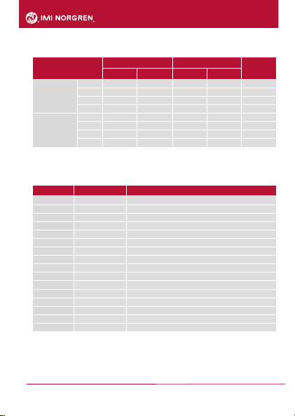
10.3 Setting ranges
SPx / FHx rPx / FLx AP
min max min max
PQ7809
bar
-0,98
1,00
-0,99
0,99
0,01
kPa
-98
100
-99
99
1
PSI
-14,2
14,6
-14,4
14,4
0,2
inHG
-28,8
29,7
-29,1
29,4
0,3
PQ7834
bar
-0,90
10,00
-0,95
9,95
0,05
kPa
-90
1000
-95
995
5
PSI
-13
145
-14
144
1
inHG
-26
296
-28
294
2
PQ7809 --> 54D-V101-DD0-AA
PQ7834 --> 54D-V110-DD0-AA
11. Factory setting
Werkseinstellung Benutzer-Einstellung / Kommentare
SP1 / FH1
25% VMR*
rP1 / FL1
23% VMR*
ou1
Hno
ou2
Hno
SP2/FH2
75% VMR*
rP2/FL2
73% VMR*
coF
0,0
SySP
0,0
dS1
0
dr1
0
dS2
0
dr2
0
dAP
6
diS
d2
uni
bAr
cLor
r-on
* = the indicated percentage of the final value of the measuring range (VMR) of the corresponding
sensor is set in bar

19
Electronic Pressure Sensor 54D
Operation manual
7503761000000050 05/2019

20
Electronic Pressure Sensor 54D
Operation manual
7503761000000050 05/2019
The data specified above only serve to describe the product.
No statements concerning a certain condition or suitability for a certain
application can be derived from our information.
The given information does not release the user from the obligation of
own judgement and verification.
It must be remembered that our products are subject to a natural process
of wear and aging.
© This document, as well as the data, specifications and other
informations set forth in it, are the exclusive property of Norgren GmbH.
Without their consent it may not be reproduced or given to third parties.
Subject to modifications.
Printed in Germany.
These instructions were originally generated in German.These
instructions were originally generated in German.
Order no. 7503761000000050
Table of contents
Other IMI NORGREN Accessories manuals


