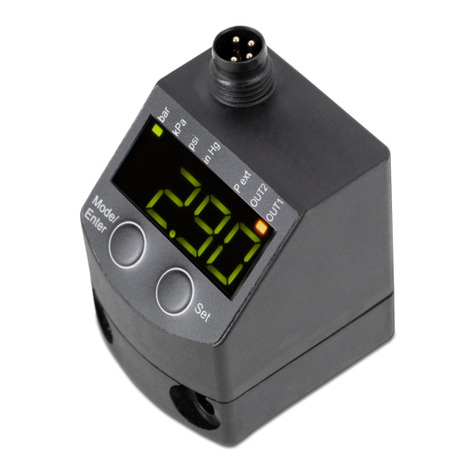
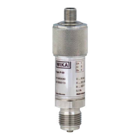
IMI NORGREN 34D Series User manual

Operation manual
for versions:
34D-xxxxx-DDx-xx
2 x PNP (1 x IO-Link,
Configurable)
Electronic
Pressure Sensor
34D

2
Electronic Pressure Sensor 34D
Operation manual
7503755000000050 05/2019
Content
1. Preliminary note 4
1.1 Symbols used 4
2. Safety instructions 4
3. Intended Use 5
3.1 Applications 5
4. Function 6
4.1 Communication, parameter setting, evaluation 6
4.2 Switching function 6
4.3 IO-Link 7
5. Installation 7
6. Electrical connection 8
7. Operating and display elements 9
8. Menu 10
8.1 Menu structure: Main menu 10
8.2 Explanation of the menu 11
8.2.1 Explanation of the menu level 1 11
8.2.2 Explanation of the menu level 2 11
9. Parameter setting 12
9.1 Parameter setting in general 12
9.2 Configure display (optional) 15
9.3 Set output signals 15
9.3.1 Set output functions 15
9.3.2 Define switching limits for the hysteresis function 16
9.3.3 Define switching limits for the window function 16
9.4 User settings (optional) 16
9.4.1 Set delay for the switching outputs 16
9.4.2 Set output logic for the switching outputs 16
9.4.3 Set damping for the switching signal 16

3
Electronic Pressure Sensor 34D
Operation manual
7503755000000050 05/2019
9.4.4 Read min-/max values for the system pressure 17
9.4.5 Reset all parameters to factory setting 17
9.4.6 Set colour change of the display 17
9.4.7 Graphical illustration of the colour change of the display 18
10. Operation 21
10.1 Read set parameters 21
10.2 Self-diagnosis / error indications 21
11. Technical data 22
11.1 Setting ranges 22
11.2 Further technical data 22
12 Factory setting 23

4
Electronic Pressure Sensor 34D
Operation manual
7503755000000050 05/2019
1. Preliminary note
1.1 Symbols used
►Instructions
> Reaction, result
[…] Designation of keys, buttons or displays
→Cross-reference
Important note, Non-compliance can result in malfunction or interference.
Information
Supplementary note
2. Safety instructions
Please read this document prior to set-up of the unit. Ensure that the product is suitable for your
application without any restrictions.
If the operating instructions or the technical data are not adhered to, personal injury and/or
damage to property can occur.
Check the compatibility of the product materials with the media to be measured in all
applications.
Correct condition of the device for the operating time can only be guaranteed if the device is
only used for media to which the wetted materials are sufficiently resistant → 3.1 Applications.
If the devices are used in gas applications with pressures > 25 bar the notes in chapter 3.1 for
devices with the marking *), must be absolutely observed.
The responsibility whether the measurement device is suitable for the respective application
lies with the operator. The manufacturer assumes no liability for consequences of misuse by
the operator. Improper installation and use of the devices results in a loss of the warranty claims.

5
Electronic Pressure Sensor 34D
Operation manual
7503755000000050 05/2019
3. Intended Use
The device monitors the system pressure of machines and installations.
3.1 Applications
Type of pressure: relative pressure
Order number Measuring range Permissible
overpressure *)
Bursting pressure
bar
PSI
bar
PSI
bar
PSI
Pressure sensors with internal thread G¼
34D-P600…
0…600
0…8700
800
11580
2500
36250
34D-P400…
0…400
0…5800
800
11580
1700
24650
34D-P250…
0…250
0…3625
500
7250
1200
17400
34D-P160…
0…160
0…2320
350
5075
1000
14500
34D-P100…
0…100
0…1450
300
4350
650
9400
34D-P040…
0…40
0…580
200
2900
500
7250
34D-P016…
0…16
0…232
85
1225
500
2900
34D-V110…
-1…10
-14,5…145
75
1087
150
2175
34D-V101…
-1…1
-14,5…14,5
10
145
30
450
*
)
With static overload pressure or max. 100 million pressure cycles.
MPa = (measured value in bar) ÷ 10
kPa = (measured value in bar) x 100
Media used must be compatible with the materials specified in the data sheet
Avoid static and dynamic overpressure exceeding the specified overload pressure by taking
appropriate measures.
The indicated bursting pressure must not be exceeded.
Even if the bursting pressure is exceeded only for a short time, the unit may be destroyed.
ATTENTION: Risk of injury!

6
Electronic Pressure Sensor 34D
Operation manual
7503755000000050 05/2019
4. Function
The unit displays the current system pressure.
It generates output signals according to the operating mode and the parameter setting.
It moreover provides the process data via IO-Link.
The unit is laid out for fully bidirectional communication. So, the following options are possible:
oRemote display: reading and display of the current system pressure.
oRemote parameter setting: reading and changing the current parameter setting. - IO-
Link parameter setting → 4.3
4.1 Communication, parameter setting, evaluation
OUT1 (Pin 4)
Switching signal for system pressure limit value
Communication via IO-Link
OUT2 (Pin 2) Switching signal for system pressure limit value
4.2 Switching function
OUTx changes its switching state if it is above or below the set switching limits (SPx, rPx). The
following switching functions can be selected:
Hysteresis function / normally open: [OUx] = [Hno] (→ fig. 1)
Hysteresis function / normally closed: [OUx] = [Hnc] (→ fig. 1)
First the set point (SPx) is set, then the reset point (rPx). The hysteresis defined remains even if
SPx is changed again.
Window function / normally open: [OUx] = [Fno] (→ fig. 2).
Window function / normally closed: [OUx] = [Fnc] (→ fig. 2).
The width of the window can be set by means of the difference between FHx and FLx. FHx =
upper value, FLx = lower value.
P = system pressure; HY = hysteresis; FE = window
t
P
SP
rP
1
0
1
0
Hno
Hnc
HY
FH
FL
1
2

7
Electronic Pressure Sensor 34D
Operation manual
7503755000000050 05/2019
4.3 IO-Link General Information
This unit has an IO-Link communication interface which requires an IO-Link-capable module (IO-
Link master) for operation.
The IO-Link interface enables direct access to the process and diagnostic data and provides the
possibility to set the parameters of the unit during operation.
In addition communication is possible via a point-to-point connection with a USB adapter cable.
Device-specific Information
You can find the IODDs necessary for the configuration of the IO-Link unit and detailed information
about process data structure,
Diagnostic information and parameter addresses at http://s.norgren.com/34d
Parameter setting tools
You will find all necessary information about the required IO-Link hardware and software at
http://s.norgren.com/34d
5. Installation
Before installing and removing the unit: Make sure that no pressure is applied to the system.
►Insert the unit in a G¼ process connection.
►Tighten firmly.
Recommended tightening torque: 25 to 35 Nm

8
Electronic Pressure Sensor 34D
Operation manual
7503755000000050 05/2019
6. Electrical connection
The unit must be connected by a qualified electrician. The national and international
regulations for the installation of electrical equipment must be adhered to.
Voltage supply according to EN 50178, SELV, PELV.
►Disconnect power.
►Connect the unit as follows:
Core colours
BK
black
BN
brown
BU
blue
WH
white
OUT1: Binary switching output or IO-Link
OUT2: Binary switching output
Colours to DIN EN 60947-5-6
Example circuits
2 x positive switching
2 x negative switching
L
L
+
3
4
2
1
BU
BK
WH
BN
2:
2
OUT
4:
OUT
1
2
1
BN
WH
BK
BU
4
1
3
2
OUT2
L
+
L-
OUT1
L
L
+
3
4
2
1
BU
BK
WH
BN
2:
2
OUT
4:
OUT
1
3
4

9
Electronic Pressure Sensor 34D
Operation manual
7503755000000050 05/2019
7. Operating and display elements
1 to 8: Indicator LEDs
LED 1
Switching status OUT1 (lights when output 1 is switched).
LED 8
Switching status OUT2 (lights when output 2 is switched).
LED 2 - 7
System pressure in the indicated unit of measurement.
9: [Enter] button [●]
- Selection of the parameters and acknowledgement of the parameter values.
10 to 11: Arrow keys up [▲] and down [▼]
- Setting of the parameter values (scrolling by holding pressed; incremental by pressing once).
12: Alphanumeric display, 4 digits
- Display of the current system pressure.
- Indication of the parameters and parameter values.

10
Electronic Pressure Sensor 34D
Operation manual
7503755000000050 05/2019
8. Menu
8.1 Menu structure: Main menu

11
Electronic Pressure Sensor 34D
Operation manual
7503755000000050 05/2019
8.2 Explanation of the menu
8.2.1 Explanation of the menu level 1
SPx/rPx Upper / lower limit value for system pressure at which OUT1
switches with hysteresis setting. SPx/rPx is displayed if the
parameter [Hno] or [Hnc] for OUTx was set in the extended
functions "EF" menu.
FHx/FLx Upper / lower limit value for system pressure at which OUT1
switches with window setting. FHx/FLx is displayed if the
parameter [Fno] or [Fnc] for OUTx was set in the extended
functions "EF" menu.
EF Extended functions / opening of menu level 2.
8.2.2 Explanation of the menu level 2
rES Restore factory setting.
ou1 Output function for OUT1:
• Switching signal for the pressure limit values: hysteresis
function [H ..] or window function [F ..], either normally open [.
no] or normally closed [. nc].
ou2 Output function for OUT2:
• Switching signal for the pressure limit values: hysteresis
function [H . .] or window function [F . .] as normally open (. no)
or normally closed (. nc) each.
dS1 / dS2 Switching delays for OUT1 / OUT2.
dr1 / dr2 Switch-off delay for OUT1 / OUT2.
uni Standard unit of measurement for system pressure (display):
[bAr] / [mbar] / [MPA] / [kPA] / [PSI] / [inHG] .
P-n Output logic: pnp / npn.
Lo Minimum value memory for system pressure.
Hi Maximum value memory for system pressure.
dAP Damping of the measured signal.
coLr Assignment of the display colours "red" and "green" within the
measuring range.
cFL / cFH
Lower / upper value for colour change.
Parameter only active after selection of a freely definable colour
window in the coLr parameter: [r-cF] or [G-cF
diS Update rate and orientation of the display.

12
Electronic Pressure Sensor 34D
Operation manual
7503755000000050 05/2019
9. Parameter setting
During parameter setting the unit remains in the operating mode. It continues to monitor with the
existing parameters until the parameter setting has been completed.
9.1 Parameter setting in general
1
Select parameter
►Press [●] to get to the menu.
►[▲►▼]Press [▲] or [▼] until the
requested parameter is displayed.
2
Set parameter value
►Press [●] to edit the selected para-meter.
►[▲Press [▲] ▼or [▼] for min. 2 s.
> After 2 s: setting value is changed:
incrementally by pressing the button
once or continuously by keeping the
button pressed.
Numerical values are incremented continuously with ▲[▲] or decremented with [▼].▼] .
3
Acknowledge parameter
value ►Briefly press [●].
> The parameter is displayed again.
The new setting value is saved.
Set other parameters
►Press [▲] or [▼] until the requested parameter is displayed.
Finish parameter setting
►Press [▲] or [▼] several times until the current measured value is displayed or wait for 30 s. >
The unit returns to the process value display.

13
Electronic Pressure Sensor 34D
Operation manual
7503755000000050 05/2019
Each parameter setting requires 3 steps:
If [C.Loc] is displayed when an attempt is made to modify a parameter value, an IO-Link
communication is active (temporary locking).
If [S.Loc] is displayed, the sensor is permanently locked via software. This locking can only
be removed using a parameter setting software.
Change from menu level 1 to menu level 2:
►Press [●] to get to the menu.
►Press [▼] or [▼] until [EF] is dis-played.
►Press [●].
> The first parameter of the submenu is
displayed (here: [rES]).
Change from menu level 1 to menu level 2 when a parameter setting software is used:
►Activate the [EF] button.

14
Electronic Pressure Sensor 34D
Operation manual
7503755000000050 05/2019
Locking / unlocking
The unit can be locked electronically to prevent unintentional settings.
On delivery: not locked.
Timeout:
If no button is pressed for 30 s during parameter setting, the unit returns to the operating mode
with unchanged values.
►Make sure that the unit is in
the normal operating mode.
►Press [▲] + [▼]
simultaneously for 10 s.
> [Loc] is displayed.
10 s
During operation: [Loc] is briefly displayed if you try to change parameter values.
For unlocking:
►Press [▲] + [▼]
simultaneously for 10 s.
> [uLoc] is displayed.
10 s

15
Electronic Pressure Sensor 34D
Operation manual
7503755000000050 05/2019
9.2 Configure display (optional)
►Select [Uni] and set the unit of measurement:
[bAr], [mbAr],
[MPA], [kPA],
[PSI],
[inHG]
The selectable units of measurement depend on the respective unit.
►Select [diS] and set the update rate and orientation of the display:
[d1]: update of the measured values every 50 ms.
[d2]: update of the measured values every 200 ms.
[d3]: update of the measured values every 600 ms.
[rd1], [rd2], [rd3]: display as for d1, d2, d3; rotated by 180°.
[OFF] = The measured value display is deactivated in the Run mode. The LEDs
remain active even if the display is deactivated.
Error messages are displayed even if the display is deactivated.
Even with unsteady pressure characteristics [d1] provides optimum
readability; the corresponding algorithms are stored.
9.3 Set output signals
9.3.1 Set output functions
►Select [ou1] and set the switching function:
[Hno] = hysteresis function/NO,
[Hnc] = hysteresis function/NC,
[Fno] = window function/NO,
[Fnc] = window function/NC.
►Select [OU2] and set the function:
[Hno] = hysteresis function/NO,
[Hnc] = hysteresis function/NC,
[Fno] = window function/NO,
[Fnc] = window function/NC.

16
Electronic Pressure Sensor 34D
Operation manual
7503755000000050 05/2019
9.3.2 Define switching limits for the hysteresis function
►[ou1] / [ou2] must be set as [Hno] or [Hnc].
►Select [SP1] / [SP2] and set the value at which the output is set.
►Select [rP1] / [rP2] and set the value at which the output is reset.
rPx is always smaller than SPx. The unit only accepts values which are lower than
the value for SPx.
9.3.3 Define switching limits for the window function
►[ou1] /[ou2] must be set as [Fno] or [Fnc].
►Select [FH1] / [FH2] and set the upper limit value.
►Select [FL1] / [FL2] and set the lower limit value.
FLx is always lower than FHx. The unit only accepts values which are lower than
the value for FHx.
9.4 User settings (optional)
9.4.1 Set delay for the switching outputs
[dS1] / [dS2] = switching delay for OUT1 / OUT2.
[dr1] / [dr2] = reset delay for OUT1 / OUT2.
►Select [dS1], [dS2], [dr1] or [dr2] and set a value between 0 and 50 s (at 0 the
delay time is not active).
For this unit the parameters [dSx] und [drx] for the set and reset points
are designed strictly to the VDMA guideline.
9.4.2 Set output logic for the switching outputs
►Select [P-n] and set [PnP] or [nPn].
9.4.3 Set damping for the switching signal
►Select [dAP], set the value in seconds; setting range 0.000...4.000 s (T value:
63 %). At 0.00 [dAP] is not active.

17
Electronic Pressure Sensor 34D
Operation manual
7503755000000050 05/2019
9.4.4 Read min-/max values for the system pressure
►Select [HI] or [Lo] and briefly press [●]. [HI] = maximum value, [LO] = minimum
value. Delete memory:
►Select [HI] or [LO].
►Press and hold [▲] or [▼] until [----] is displayed. ► Briefly press [●].
9.4.5 Reset all parameters to factory setting
►Select [rES].
►Press [●].
►Press and hold [▲] or [▼] until [----] is displayed. ► Briefly press [●].
We recommend noting down your own settings before carrying out a reset
(→ 12 Factory setting).
9.4.6 Set colour change of the display
►Select [coLr] and set the function:
- [rEd] = display colour red (independent of the measured value).
- [GrEn] = display colour green (independent of the measured value).
- [r1ou] = display colour red when OUT1 switches
- [G1ou] = display colour green when OUT1 switches.
- [r2ou] = display colour red when OUT2 switches.
- [G2ou] = display colour green when OUT2 switches.
- [r-12] = Display colour red when the measured value is between
the limit values of OUT1 and OUT2.
- [G-12] = Display colour green when the measured value is between
the limit values of OUT1 and OUT2.
- [r-cF] = Display colour red when the measured value is between
the freely definable limit)values
[cFL]*) and [cFH])*).
- [G-cF] = Display colour green when the measured value is between
the freely definable limit values
[cFL])*) and [cFH)]*).
*) *) The parameters [cFL] and [cFH] can only be selected in the menu tree when [r-
cF] or [G-cF] were activated.
►Select [cFL] and set the lower limit value
(only possible when [r-cF] or [G-cF] were activated).
> The setting range corresponds to the measuring range and its maximum limit is
[cFH].
►Select [cFH] and set the upper limit value.
(only possible when [r-cF] or [G-cF] were activated).
> The setting range corresponds to the measuring range and its minimum limit is
[cFL].

18
Electronic Pressure Sensor 34D
Operation manual
7503755000000050 05/2019
9.4.7 Graphical illustration of the colour change of the display
Display colour change for the parameters
[r1ou] / [r2ou], mode window function
Display colour change for the parameters
[G1ou] / [G2ou], mode window function.
Measured value between FL1/FL2 and
FH1/FH2; Display = red
Measured value between FL1/FL2 and
FH1/FH2; Display = green
Colour change display green
Colour change display red
1
Initial value of the measuring range
2
Final value of the measuring range
Display colour change for the parameters
[r1ou] / [r2ou], mode hysteresis
function
Display colour change for the parameters
[G1ou] / [G2ou], mode hysteresis
function
Measured value > switch point
OUT1/OUT2; Display = red
Measured value > switch point
OUT1/OUT2; Display = green
1
2
FL1/
FL2
FH1
/
FH2
1
2
FL1/
FL2
FH1
/
FH2
1
2
OUT1/
OUT2
1
OUT1/
OUT2
2

19
Electronic Pressure Sensor 34D
Operation manual
7503755000000050 05/2019
Display colour change for the parameters
[r-12],
mode hysteresis function
Display colour change for the parameters
[G-
12], mode hysteresis function
Measured value between OUT1 and OUT2;
Display = red
Measured value between OUT1 and OUT2;
Display =
green
Display colour change for the parameters
[r-12],
mode window function
Display colour change for the parameters
[G-
12], mode window function
FL2
FH2
FL2
FH2
Measured value outside FL1...FH1 and
FL2...FH2; Display = red
Measured value outside FL1...FH1 and
FL2...FH2; Display = green
Colour change display green
Colour change display red
1
Initial value of the measuring range
2
Final value of the measuring range
FL1/FL2
Lower limit value window function outputs OUT1 / OUT2
FH1/FH2
Upper limit value window function outputs OUT1 / OUT2
1
OUT
1
2
OUT
2
1
OUT1
2
OUT2
1
FL1
2
FH1
1
FL1
2
FH1

20
Electronic Pressure Sensor 34D
Operation manual
7503755000000050 05/2019
Display colour change with parameter [r-cF]
independent of OUT1 / OUT2.
Display colour change with parameter [G-cF]
independent of OUT1 / OUT2
Measured value between cFL and cFH; Display
= red
Measured value between cFL and cFH; Display
= green
1
cFL
2
cFH
1
cFL
2
cFH
This manual suits for next models
9
Table of contents
Other IMI NORGREN Accessories manuals
Popular Accessories manuals by other brands
DOUXE
DOUXE S3 Active Stylus Pen instruction manual

FirstHealth
FirstHealth FH7020 instruction manual

Murdock
Murdock A311.8 Series Installation & maintenance instructions

SOMFY
SOMFY TaHoma 2401368 installation guide

PCB Piezotronics
PCB Piezotronics IMI SENSORS M641B11 Installation and operating manual

Goldair
Goldair PLATINUM GPEBSQ Series operating instructions