IMI SENSORS A Series User manual

Model EXM643A11
4-20 mA Output Velocity Sensor
Installation and Operating Manual
For assistance with the operation of this product,
contact PCB Piezotronics, Inc.
Toll-free: 800-959-4464
24-hour SensorLine: 716-684-0001
Fax: 716-684-3823
E-mail: [email protected]
Web: www.imi-sensors.com

The information contained in this document supersedes all similar information that
may be found elsewhere in this manual.
Total Customer Satisfaction – PCB
Piezotronics guarantees Total Customer
Satisfaction. If, at any time, for any
reason, you are not completely satisfied
with any PCB product, PCB will repair,
replace, or exchange it at no charge. You
may also choose to have your purchase
price refunded in lieu of the repair,
replacement, or exchange of the product.
Service – Due to the sophisticated nature
of the sensors and associated
instrumentation provided by PCB
Piezotronics, user servicing or repair is
not recommended and, if attempted, may
void the factory warranty. Routine
maintenance, such as the cleaning of
electrical connectors, housings, and
mounting surfaces with solutions and
techniques that will not harm the
physical material of construction, is
acceptable. Caution should be observed
to insure that liquids are not permitted to
migrate into devices that are not
hermetically sealed. Such devices should
only be wiped with a dampened cloth
and never submerged or have liquids
poured upon them.
Repair – In the event that equipment
becomes damaged or ceases to operate,
arrangements should be made to return
the equipment to PCB Piezotronics for
repair. User servicing or repair is not
recommended and, if attempted, may
void the factory warranty.
Calibration – Routine calibration of
sensors and associated instrumentation is
recommended as this helps build
confidence in measurement accuracy and
acquired data. Equipment calibration
cycles are typically established by the
users own quality regimen. When in
doubt about a calibration cycle, a good
“rule of thumb” is to recalibrate on an
annual basis. It is also good practice to
recalibrate after exposure to any severe
temperature extreme, shock, load, or
other environmental influence, or prior
to any critical test.
PCB Piezotronics maintains an ISO-
9001 certified metrology laboratory and
offers calibration services, which are
accredited by A2LA to ISO/IEC 17025,
with full traceablility to N.I.S.T. In
addition to the normally supplied
calibration, special testing is also
available, such as: sensitivity at elevated
or cryogenic temperatures, phase
response, extended high or low
frequency response, extended range, leak
testing, hydrostatic pressure testing, and
others. For information on standard
recalibration services or special testing,
contact your local PCB Piezotronics
distributor, sales representative, or
factory customer service representative.
Returning Equipment – Following
these procedures will insure that your
returned materials are handled in the
most expedient manner. Before returning
any equipment to PCB Piezotronics,
contact your local distributor, sales
representative, or factory customer
service representative to obtain a Return
Warranty, Service, Repair, and
Return Policies and Instructions

Materials Authorization (RMA)
Number. This RMA number should be
clearly marked on the outside of all
package(s) and on the packing list(s)
accompanying the shipment. A detailed
account of the nature of the problem(s)
being experienced with the equipment
should also be included inside the
package(s) containing any returned
materials.
A Purchase Order, included with the
returned materials, will expedite the
turn-around of serviced equipment. It is
recommended to include authorization
on the Purchase Order for PCB to
proceed with any repairs, as long as they
do not exceed 50% of the replacement
cost of the returned item(s). PCB will
provide a price quotation or replacement
recommendation for any item whose
repair costs would exceed 50% of
replacement cost, or any item that is not
economically feasible to repair. For
routine calibration services, the Purchase
Order should include authorization to
proceed and return at current pricing,
which can be obtained from a factory
customer service representative.
Warranty – All equipment and repair
services provided by PCB Piezotronics,
Inc. are covered by a limited warranty
against defective material and
workmanship for a period of one year
from date of original purchase. Contact
PCB for a complete statement of our
warranty. Expendable items, such as
batteries and mounting hardware, are not
covered by warranty. Mechanical
damage to equipment due to improper
use is not covered by warranty.
Electronic circuitry failure caused by the
introduction of unregulated or improper
excitation power or electrostatic
discharge is not covered by warranty.
Contact Information – International
customers should direct all inquiries to
their local distributor or sales office. A
complete list of distributors and offices
can be found at www.pcb.com.
Customers within the United States may
contact their local sales representative or
a factory customer service
representative. A complete list of sales
representatives can be found at
www.pcb.com. Toll-free telephone
numbers for a factory customer service
representative, in the division
responsible for this product, can be
found on the title page at the front of this
manual. Our ship to address and general
contact numbers are:
PCB Piezotronics, Inc.
3425 Walden Ave.
Depew, NY 14043 USA
Toll-free: (800) 828-8840
24-hour SensorLineSM: (716) 684-0001
Website: www.pcb.com
DOCUMENT NUMBER: 21354
DOCUMENT REVISION: B
ECN: 17900
SENSOR
S AND INSTRUMENTATIO
N FOR MACHINE CONDIT
ION MONITORING
Model 642/643/647/648 A Series Industrial 4-20mA Sensor
Operating Guide with Enclosed Warranty Information
3425 Walden Avenue, Depew, New York 14043-2495
Phone (716) 684-0003
Fax (716) 684-3823
Toll Free Line 1-800-959-4IMI
MANUAL NUMBER: 25778
MANUAL REVISION: C
ECN NUMBER: xxxxx

PAGE 2
SENSORS AND INSTRUME
NTATION FOR MACHINE
CONDITION MONITORING
Table of Contents
Introduction...................................................................................................................... Page 3
General Features
Dimension Drawing.......................................................................................................... Page 4
Operation and Wiring....................................................................................................... Page 5
Standard Wiring
Taking Measurements
RV Option
TO Option
Installation........................................................................................................................ Page 9
ESD Sensitivity.............................................................................................................. Page 10
Warranty/Servicing
Warranty, Service & Return Procedure.......................................................................... Page 11
Customer Service.......................................................................................................... Page 12

PAGE 3
SENSORS AND INSTRUME
NTATION FOR MACHINE
CONDITION MONITORING
Introduction
The Model 642/643/647/648 A Series Industrial 4-20mA Sensors combine the capabilities of a piezoelectric
vibration sensor and a 4-20mA vibration transmitter. The sensor outputs a 4-20mA signal that is proportional to
the overall velocity or acceleration of the machinery. Ideal for monitoring the vibration of process equipment such
as fans, motors and pumps, the output of the sensor is used for process control or predictive maintenance. There
are many options in this series. Please refer to specific specification sheets for further details.
General Features
Imbedded Piezoelectric Accelerometer for improved accuracy and frequency response.
Vibration range can be in Acceleration or Velocity.
Allows for continuous vibration monitoring of critical applications.
Reduces sophisticated vibration analysis requirements.
RV (Raw Vibration) option for conducting frequency analysis and machinery diagnostics.
TO (Temperature Output) option via an independent 4-20mA loop.
Readily interfaces to existing process control and predictive maintenance equipment.
Rugged stainless steel construction for applications in harsh environments.
Flexible design allows for various custom requirements.
Swivel mount simplifies installation.
Cable may be positioned in any direction.
PAGE 4
SENSORS AND INSTRUME
NTATION FOR MACHINE
CONDITION MONITORING
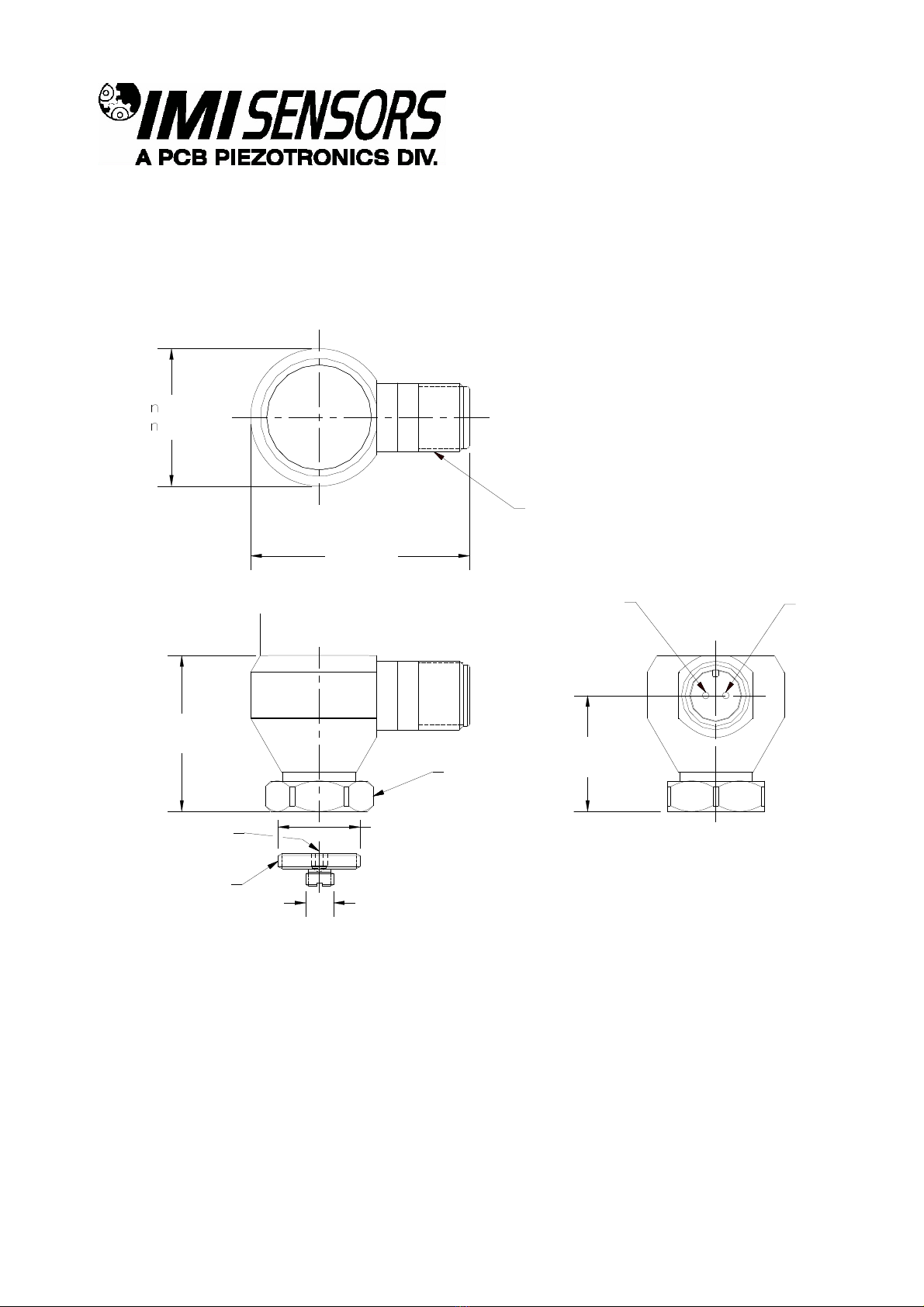
Dimension Drawing
1.05
[26.7]
PIN B:
NEGATIVE
4-20 mA
PIN A:
POSITIVE
4-20 mA
1/8" HEX ALLEN
KEY REQUIRED
MOUNTING STUD
MODEL 080A162
(SUPPLIED) 1/4-28 UNF-2A
3/4-16 UNF-2A
1.41
[35.8] 7/8 (22) HEX
1.98[45.7]
1.24
[ 31.5]
ELECTRICAL CONNECTOR
5/8-24 UNEF-2A
2 - PIN (MIL-C-5015)
Inch (mm)

PAGE 5
SENSORS AND INSTRUME
NTATION FOR MACHINE
CONDITION MONITORING
Operation and Wiring
Standard Wiring
The Model 642/643/647/648 A Series operates from a standard 2-wire, 4-20mA loop. If using a loop powered
unit, attach the positive (+) input from the power supply to Pin A or Red wire on the sensor and the negative (-)
input from the power supply to Pin B or Blue wire of the sensor.
Figure 1 –wiring: loop powered Figure 2 –wiring: loop powered/DC source
If using a standard DC power supply, install either an ammeter and/or load resistor in line with the output, Pin B or
Blue wire.
The resistor will generate a DC voltage that is proportional to current by:
V
IR
If R ohms and I mA thenV VDC
500 6 3,
Note:
- Resistor value must be less than: (Vsupply –12) x 50.
- For integral cable sensors: RED wire is positive, BLUE wire is negative.

PAGE 6
SENSORS AND INSTRUME
NTATION FOR MACHINE
CONDITION MONITORING
Taking Measurements
When measuring the current output from the unit, use the following formula to calculate the vibration level:
Vibration Output = (Measured Output –4mA) x (Full Scale Vibration Output /16mA)
Measured mA 642AX0 642AX1 642AX2
4.00 0.0 ips, pk 0.0 ips, pk 0.0 ips, pk
8.00 0.125 ips, pk 0.25 ips, pk 0.5 ips, pk
12.0 0.25 ips, pk 0.5 ips, pk 1.0 ips, pk
15.75 0.37 ips, pk 0.73 ips, pk 1.47 ips, pk
20 0.5 ips, pk 1.0 ips, pk 2.0 ips, pk
Measured mA 643AX0 643AX1 643AX2
4.00 0.0 ips, rms 0.0 ips, rms 0.0 ips, rms
8.00 0.125 ips, rms 0.25 ips, rms 0.5 ips, rms
12.0 0.25 ips, rms 0.5 ips, rms 1.0 ips, rms
15.75 0.37 ips, rms 0.73 ips, rms 1.47 ips, rms
20 0.5 ips, rms 1.0 ips, rms 2.0 ips, rms
Measured mA 647 648
4.00 0.0 g rms 0.0 g rms
8.00 1.25 g rms 2.50 g rms
12.0 2.50 g rms 5.00 g rms
15.75 3.67 g rms 7.34 g rms
20 5.00 g rms 10.0 g rms

PAGE 7
SENSORS AND INSTRUME
NTATION FOR MACHINE
CONDITION MONITORING
RV Option
The RV (raw vibration) option includes a 100mV/g ±20% additional output. The accelerometer frequency range is
1 Hz-10 kHz, maximum amplitude of 15 g-pk. Data collectors or analyzers can use this vibration signal for further
analysis.
Figure 3 –RV wiring
For integral cable sensors:
RED 4-20mA Positive
BLACK 4-20mA Negative (same as green)
GREEN -RV Acceleration Negative (same as black)
WHITE +RV Acceleration Positive
Note:
-The Acceleration Signal Negative has to be isolated from any grounding. If this terminal is grounded, the 4-
20mA loop will short, causing no output.
-The acceleration output signal is ideally suited for use with portable battery powered data collectors or analyzers.

PAGE 8
SENSORS AND INSTRUME
NTATION FOR MACHINE
CONDITION MONITORING
TO Option
The TO (Temperature Output) option includes an additional independent 4-20mA output for temperature
measurement. The temperature range is from -40°C to 125°C with an overall accuracy of ±5%FSO. The
imbedded temperature sensor monitors the environment internal to the sensor housing and is situated at
approximately mid level.
Figure 4 –TO wiring
For integral cable sensors:
RED 4-20mA Vibration Positive
BLACK 4-20mA Vibration Negative
GREEN 4-20mA Temperature Negative
WHITE 4-20mA Temperature Positive
Note:
- The same power supply can be used for both4-20mA loops. Connect the both positive terminals to directly to the
power supply, then use the negative terminals for independent process loops.

PAGE 9
SENSORS AND INSTRUME
NTATION FOR MACHINE
CONDITION MONITORING
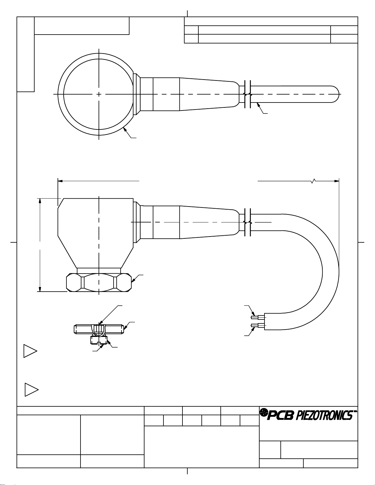
Installation
Installation should be performed per the following detail drawing for best performance.

PAGE 10
SENSORS AND INSTRUME
NTATION FOR MACHINE
CONDITION MONITORING
Warning 1 –ESD sensitivity
The power supply/signal conditioner should not be opened by anyone other than qualified service
personnel. This product is intended for use by qualified personnel who recognize shock hazards and are familiar
with the safety precautions required to avoid injury.
Warning 2 –ESD sensitivity
This equipment is designed with user safety in mind; however, the protection provided by the equipment may be
impaired if the equipment is used in a manner not specified by PCB Piezotronics, Inc.
Caution 1 –ESD sensitivity
Cables can kill your equipment. High voltage electrostatic discharge (ESD) can damage electrical devices.
Similar to a capacitor, a cable can hold a charge caused by triboelectric transfer, such as that which occurs in the
following:
Laying on and moving across a rug,
Any movement through air,
The action of rolling out a cable, and/or
Contact with a non-grounded person.
The PCB solution for product safety:
Connect the cables only with the AC power off.
Temporarily “short”the end of the cable before attaching it to any signal input or output.
Caution 2 –ESD sensitivity
ESD considerations should be made prior to performing any internal adjustments on the equipment. Any
piece of electronic equipment is vulnerable to ESD when opened for adjustments. Internal adjustments should
therefore be done ONLY at an ESD-safe work area. Many products have ESD protection, but the level of
protection may be exceeded by extremely high voltage.

PAGE 11
SENSORS AND INSTRUME
NTATION FOR MACHINE
CONDITION MONITORING
Warranty
IMI instrumentation is warranted against defective material and workmanship for 1 year unless otherwise
expressly specified. Damage to instruments caused by incorrect power or misapplication, is not covered by
warranty. If there are any questions regarding power, intended application, or general usage, please consult with
your local sales contact or distributor. Batteries and other expendable hardware items are not covered by
warranty.
Service
Because of the sophisticated nature of IMI instrumentation, field repair is typically NOT recommended and may
void any warranty. If factory service is required, return the instrumentation according to the “Return Procedure”
stated below. A repair and/or replacement quotation will be provided prior to servicing at no charge. Before
returning the unit, please consult a factory IMI applications engineer concerning the situation as certain problems
can often be corrected with simple on-site procedures.
Return procedure
To expedite returned instrumentation, contact a factory IMI applications engineer for a RETURN MATERIAL
AUTHORIZATION (RMA) NUMBER. Please have information available such as model and serial number. Also,
to insure efficient service, provide a written description of the symptoms and problems with the equipment to a
local sales representative or distributor, or contact IMI if none are located in your area.
Customers outside the U.S. should consult their local IMI distributor for information on returning equipment. For
exceptions, please contact the International Sales department at IMI to request shipping instructions and an RMA.
For assistance, please call (716) 684-0003, or fax us at (716) 684-3823. You may also receive assistance via e-

PAGE 12
SENSORS AND INSTRUME
NTATION FOR MACHINE
CONDITION MONITORING
Customer Service
IMI, a division of PCB Piezotronics, guarantees Total Customer Satisfaction. If, at any time, for any reason, you
are not completely satisfied with any IMI product, IMI will repair, replace, or exchange it at no charge. You may
also choose to have your purchase price refunded.
IMI offers to all customers, at no charge, 24-hour phone support. This service makes product or application
support available to our customers, day or night, seven days a week. When unforeseen problems or emergency
situations arise, call the IMI Hot Line at (716) 684-0003, and an application specialist will assist you.
3425 Walden Avenue, Depew, NY 14043-2495
Phone: (716) 684-0003
USA Fax: (716) 684-3823
INTL Fax: (716) 684-4703
ICP®is a registered trademark of PCB Group, Incorporated,
which uniquely identifies PCB sensors that incorporate built-in microelectronics.

Model Number
643A11 4-20 MA OUTPUT VELOCITY SENSOR Revision: A
ECN #: 43341
Performance ENGLISH SI
Measurement Range 0.0 to 1 in/sec rms 0 to 5.4 mm/s rms [1]
Output 4- 0 mA 4- 0 mA
Frequency Range(± 10 %) 600 to 60,000 cpm 10 to 1 kHz [ ][3]
Broadband Resolution 0.005 in/sec rms 0.13 mm/s rms [4]
Non-Linearity ± 1 % ± 1 %
Env ronmental
Temperature Range -40 to 185 °F -40 to 85 °C
Electr cal
Excitation Voltage 1 to 30 VDC 1 to 30 VDC
Settling Time(within % of value) <15 sec <15 sec
Electrical Isolation(Case) >108 Ohm >108 Ohm
Phys cal
Size (Hex x Height) 7/8 in x 1.41 in . mm x 35.8 mm
Weight(without cable) 3.8 oz 108 gm
Mounting Thread 1/4- 8 UNF 1/4- 8 UNF
Mounting Torque(Stud) 3 to 4 ft-lb 4.1 to 5.4 Nm [5][6]
Mounting Torque(hex nut) to 3 ft-lb .7 to 4.1 Nm
Sensing Element Ceramic Ceramic
Sensing Geometry Shear Shear
Housing Material Stainless Steel Stainless Steel
Sealing Welded Hermetic Welded Hermetic
Electrical Connector Integral Cable Integral Cable
Electrical Connection Position Side Side
Cable Termination Pigtail Ends Pigtail Ends
Electrical Connections(Red) 4- 0 mA Pos (+) 4- 0 mA Pos (+)
Electrical Connections(Blue) 4- 0 mA Neg (-) 4- 0 mA Neg (-)
Cable Length 10 ft 3.0 m
Cable Type Polyurethane Polyurethane
All specifications are at room temperature unless otherwise specified.
In the interest of constant product improvement, we reserve the right to change specifications without notice.
ICP® is a registered trademark of PCB Group, Inc.
EX - Hazardous Area Approval- contact factory for specific approvals
Hazardous Area Approval DIV II, CL I, GRPS A-D, ExnL,
AExnA, IIC T4
DIV II, CL I, GRPS A-D, ExnL,
AExnA, IIC T4
Hazardous Area Approval EEx ia IIC T4, -40°C≤Ta≤80°C,
II 1 G
EEx ia IIC T4, -40°C≤Ta≤80°C,
II 1 G
Hazardous Area Approval EEx nL IIC T4, -40°C≤Ta≤80°
C, II 3 G
EEx nL IIC T4, -40°C≤Ta≤80°
C, II 3 G
Hazardous Area Approval DIV I, CL I, II, III, GRPS A-G,
Exia, AExia, IIC T4
DIV I, CL I, II, III, GRPS A-G,
Exia, AExia, IIC T4
M- Metric Mount
Supplied Accessory : Model M080A163A (1) replaces Model 080A16
RV - Buffered Analog Signal Output - 100 mV/g (± 0%)
Electrical Connector Integral Cable Integral Cable
Electrical Connections(Red) 4- 0 mA Pos (+) 4- 0 mA Pos (+)
Electrical Connections(Black) 4- 0 mA Neg (-) 4- 0 mA Neg (-)
Electrical Connections(White) Signal Output Pos Signal Output Pos
Electrical Connections(Green) Signal Output Neg Signal Output Neg
NOTES:
[1]Conversion Factor 1 in/sec = 0.0 54 m/sec.
[ ]1Hz = 60 cpm (cycles per minute).
[3]Current will fluctuate at frequencies below 5 Hz.
[4]Typical value.
[5]1/8" hex Allen key required for English version, 3mm hex Allen key required for metric version.
[6]Stud torque must exceed sensor hex nut torque to ensure proper dismantling.
[7]See PCB Declaration of Conformance PS039 or PS053 for details.
SUPPLIED ACCESSORIES:
Model 080A16 Mounting Stud (1)
Model ICS-4 NIST-traceable single-axis amplitude response calibration from 0 cpm (0 Hz) to
upper 10% frequency for 4 - 0 mA output vibration sensor
34 5 Walden Avenue, Depew, NY 14043
Phone: 800-959-4464
Fax: 716-684-3823
E-Mail: imi@ cb.com
[7]
OPTIONAL VERSIONS
Optional versions have identical specifications and accessories as listed for the standard model
except where noted below. More than one option may be used.
Entered: AP Engineer: DK Sales: EGY Approved: BAM Spec Number:
Date: 10/10/ 014 Date: 10/10/ 014 Date: 10/10/ 014 Date: 10/10/ 014 35453

1
1
2
2
3
3
4
4
A A
B B
CODE
IDENT. NO.
52681
DWG. NO.
SCALE: SHEET
DRAWN CHECKED ENGINEER
TITLE
UNLESS OTHERWISE SPECIFIED TOLERANCES ARE:
DIMENSIONS IN MILLIMETERS
[ IN BRACKETS ]
XX ±0.13
ANGLES 2 DEGREES
3425 WALDEN AVE. DEPEW, NY 14043
DIMENSIONS IN INCHES
DECIMALS XX ±.01
ANGLES 2 DEGREES
FILLETS AND RADII
.003 - .005
DECIMALS X ± 0.3
FILLETS AND RADII
0.07 - 0.13
INSTALLATION DRAWING
18551
1 OF 1
FULL
MODEL 607 SERIES
XXX ±.005
JDM 10/9/14 ECB 10/9/14 DRK 10/9/14
18551
PCB Piezotronics Inc. claims proprietary rights in
the information disclosed hereon. Neither it nor any
reproduction thereof will be disclosed to others
without the written consent of PCB Piezotronics Inc.
REVISIONS
REV DESCRIPTION DIN
B ADDED METRIC MOUNTING INFORMATION 43341
FIG 1: A 1/8" HEX ALLEN
KEY IS REQUIRED FOR THE ENGLISH
MOUNTING STUD. A 3MM HEX
ALLEN KEY IS REQUIRED FOR THE
METRIC MOUNTING STUD. APPLY
SILICONE GREASE TO ALL MOUNTING
SURFACES (SEE ARROWS FIG 1 & 2)
FIG 2: TIGHTEN THE
MOUNTING STUD USING
THE ALLEN KEY. TORQUE
THE MOUNTING STUD TO
WITHIN 3 TO 4 FT-LBS.
(4.1 TO 5.4 Nm)
FIG 3: THREAD THE SENSOR'S
HEX NUT ONTO THE MOUNTING
STUD. POSITION THE CABLE OR
CONNECTOR TO THE DESIRED
LOCATION AND HAND TIGHTEN
THE HEX NUT.
FIG 4: TIGHTEN THE HEX
NUT USING A TORQUE WRENCH
TO WITHIN 2 TO 3 FT-LBS
(2.7 TO 4.1 Nm) WHILE HOLDING
THE CABLE OR CONNECTOR
IN THE DESIRED LOCATION.
FIG 5: IF FOR ANY REASON THE MOUNTING
STUD DOES NOT
DISENGAGE FROM THE SENSOR, USE A
FLAT HEAD SCREW DRIVER
TO HOLD THE STUD WHILE TURNING THE
HEX NUT COUNTERCLOCKWISE
WITH A WRENCH.
SILICONE GREASE
SILICONE GREASE
2
METRIC MOUNTING HOLE PREPARATION:
DRILL Ø.199[Ø5.05] .300[7.62] MIN
TAP M6 X 1-6g .200[5.08] MIN
ENGLISH MOUNTING HOLE PREPARATION:
DRILL Ø.218[Ø5.54] .300[7.62] MIN
TAP 1/4-28 UNF-2B .200[5.08] MIN
1
3.) FOR BEST RESULTS, PLACE A THIN LAYER OF SILICONE GREASE (DOW CORNING #4 OR EQUIVALENT) ON
INTERFACE PRIOR TO MOUNTING.
MOUNTING SURFACE SHOULD BE FLAT TO WITHIN .001[0.03] TIR WITH A MINIMUM 63 [1.6 ] FINISH FOR BEST RESULTS.
DRILL PERPENDICULAR TO MOUNTING SURFACE TO WITHIN ±1°
1
2
1


1
1
2
2
A A
B B
CODE
IDENT. NO.
52681
DWG. NO.
SCALE: SHEET
DRAWN CHECKED ENGINEER
TITLE
UNLESS OTHERWISE SPECIFIED TOLERANCES ARE:
DIMENSIONS IN MILLIMETERS
[ IN BRACKETS ]
ANGLES 2 DEGREES
3425 WALDEN AVE. DEPEW, NY 14043
DIMENSIONS IN INCHES
ANGLES 2 DEGREES
FILLETS AND RADII
.003 - .005
FILLETS AND RADII
0.07 - 0.13
OUTLINE DRAWING
25777
1 OF 1
1.5X
MODEL 642A1X, M, 643A1X, M,
647A1X, M, 648A1X, M
4-20 VIBRATION SENSING TRANSMITTER
DECIMALS XX ±.03
XXX ±.010
DECIMALS X ± 0.8
XX ± 0.25
JDM 10/6/14 ECB 10/6/14 DRK 10/6/14
jmorawski07:2610/10/2014
25777
PCB Piezotronics Inc. claims proprietary rights in
the information disclosed hereon. Neither it nor any
reproduction thereof will be disclosed to others
without the written consent of PCB Piezotronics Inc.
REVISIONS
REV DESCRIPTION DIN
B UPDATED NOTE 1 43341
3/4-16 UNF - 2A
1/4-28 UNF - 2A
(METRIC VERSION
M6 X 1.0-6g)
MOUNTING STUD
MODEL 080A162
(SUPPLIED)
1
FOR METRIC ACCELEROMETER (M642A1X, M643A1X, M647A1X, M648A1X), MOUNTING STUD
MODEL M080A163A REPLACES 080A162, 3mm HEX ALLEN KEY REQUIRED.
1
.125 [3.12] HEX ALLEN
KEY REQUIRED
4.5 [114] (TO TYPICAL BENDING RADIUS)
1.41 [35.8]
1.24 [31.5]
BLUE:
NEGATIVE
4-20mA
RED:
POSITIVE
4-20mA
.88 [22.3] HEX
MOLDED 2 CONDUCTOR
SHIELDED CABLE
TERMINATING IN BLUNT CUT,
10 FEET [3 METERS]
FROM APPLICATION.
This manual suits for next models
9
Table of contents
Other IMI SENSORS Accessories manuals

IMI SENSORS
IMI SENSORS 641B01 User manual

IMI SENSORS
IMI SENSORS 640B00 User manual

IMI SENSORS
IMI SENSORS 640 B Series User manual

IMI SENSORS
IMI SENSORS Echo CS670A01 User manual

IMI SENSORS
IMI SENSORS M642A01 User manual

IMI SENSORS
IMI SENSORS 640B02 User manual

IMI SENSORS
IMI SENSORS 642A11 User manual

IMI SENSORS
IMI SENSORS HT640B02 User manual


