IMI Buschjost 84070 Series User manual

1
10/2018 EN1377027BA
Operation manual for indirect
controlled diaphragm valves
Document No. EN1377027BA Revision: 5
Translation of the original operating manual
Status as of October 2018
1 About this documentation
This operation manual guides you to guides
you to mount, operate and maintain indirect
controlled diaphragm valves safely.
1.1 Documentation validity
These mounting instructions applies to indirect
controlled diaphragm valves of series
•84070 (G thread)
•84080 (NPT thread)
in combination with these solenoid:
Series 9101 9104
84070 • •
84080 N • •
This operation manual is intended for:
plant operators, installers, maintenance and
service technicians.
1.2 Structure of safety instructions
Safety instructions warn against dangerous
situations and must be observed in particular.
Safety instructions are structured as follows:
SIGNAL WORD
Type of hazard
Consequences of non-observance
→Precautions necessary to avoid the hazard
1.3 Hazard classes (ANSI Z535.6)
!DANGER
Safety information indicates a hazardous situation
with high risk which, if not avoided, will certainly
result in death or (serious) injury.
!WARNING
Safety information indicates a hazardous situation
with moderate risk which, if not avoided, can cause
death or severe injury.
!CAUTION
Safety information indicates a hazardous situati-
on which, if not avoided, could result in minor or
moderate injury.
NOTICE
Information indicates a hazardous situation which, if
not avoided, could result damage to property.
1.4 Styles and symbols
This documentation uses the following styles
and symbols:
• list
→instruction
1.
2.
preset order of instructions
1 part number (according to part list)
1 flexible part number (section)
qreplace spare part
!+ DANGER /WARNING /CAUTION;
NOTICE: embedded safety message
given limits or fixed value
1.5 Intended use
The valve is solely intended to control or stop
a fluid flow within approved operating limits.
The fluid must only flow through the valve in
the determined flow direction.
You may only operate the valve with fluids that
will not cause any chemical reaction with the
valve’ materials or lead to abrasive effects.
Keep documentation for future use!
P
A
A
Contents
1 About this documentation 1
1.1 Documentation validity 1
1.2 Structure of safety instructions 1
1.3 Hazard classes (ANSI Z535.6) 1
1.4 Styles and symbols 1
1.5 Intended use 1
1.6 Improper use 2
1.7 Obligations of operator 2
1.8 Personnel qualification 2
1.9 Personal protection equipment 2
2 General safety instructions 2
3 Avoid damage to property 3
4 Identifying the valve 3
5 Transport and storage 3
6 Function 3
7 Mounting 4
7.1 Conditions of installation 4
7.2 Preparation 4
7.3 Mount valve to pipe line 4
8 Connect solenoid electrically 5
9 Operating conditions 5
10 Commissioning 5
10.1 Checking the switching function 5
10.2 Flooding the valve 5
11 Operation 6
12 Maintenance 6
12.1 Cleaning and visual inspection 6
12.2 Checking for tightness and strength 6
12.3 Preparing maintenance 6
12.4 Dismantling valve 6
12.5 Checking dismantled valve parts 7
12.6 Cleaning parts, checking valve seat 7
12.7 Replacing spare parts 7
12.8 Reassembling valve 7
12.9 Mounting solenoid 7
13 Re-commissioning 7
14 Decommissioning 7
15 Replacing complete valve 8
16 Trouble shooting 8
17 Return 8
18 Disposal 8
19 Directives and certificates 8
A2
84080 N NNPT thread
Series
84070
c

2
10/2018 EN1377027BA
1.6 Improper use
Only operate the valve within approved opera-
ting limits.
In the following cases it is prohibited to opera-
te the valve:
•The valve is not used for the designated
purpose.
•The valve is used beyond the permitted
operating limits. The permitted temperature
and pressure ranges are exceeded.
•Damages to the valve – e.g. cracks,
deformation – were detected but the valve
remains in operation.
•Malfunctions were detected but the valve
remains in operation.
We do not accept any liability for damages
caused by improper use.
Our guarantee expires in the following cases:
•Undue intervention and altering are done to
the valve.
•This documentation or the operating limits as
shown in the data sheet are not observed.
1.7 Obligations of operator
Product
→Over the entire life cycle of the valve all
applicable regulations must be observed.
The instructions of this operation manual
must be observed and followed.
→Initiate a risk assessment of the overall
installation, to detect potential dangers that
may occur in combination of the valve with
other components.
Persons
→Initiate the instruction of each person who
is working with the valve.
Applicable regulations about occupatio-
nal safety ad safety engineering must be
known and applied.
Documentation
→This documentation must be fully read and
understood.
→The instructions given in this operation
manual must be put into practice.
→This documentation must be available at
any time.
Markings at the operating site
→Ensure adequate warning of the risks linked
to the valve. Use in the area of the installed
valve the following warning and prohibition
sings in compliance with EN ISO 7010 and
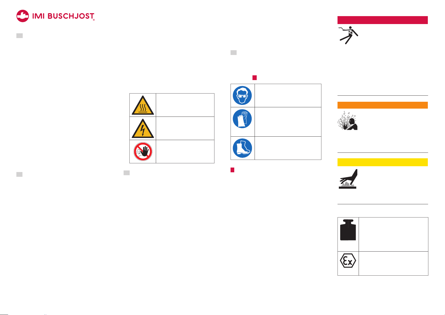
BGV A8 (VBG125):
Warning sign to indicate risk of
burns at the solenoid
Warning sign to indicate elec-
trical hazards at the solenoid
Prohibition sign to
prevent people from entering
hazardous areas
1.8 Personnel qualification
→Ensure as operator that persons who work
on or with the valve are sufficient qualified
for this job.
→Comprehensively train the operating per-
sonnel in terms of safety.
→Only allow trained specialists to perform
electric connections, commissioning, main-
tenance and trouble shooting
Demands
Operating personnel must be instructed on
operational sequences and procedures.
Operating personnel must know its responsi-
bilities regarding the work to be performed.
Trained specialists must possess profound
knowledge in mechanical engineering, electri-
cal engineering, hydraulic und pneumatic.
Trained specialists must be authorized to
commission, ground and designate devices,
systems and power circuits according to the
standards of safety technology.
Trained specialists must possess profound
knowledge about design and principle of ope-
ration of the valves and the plant.
1.9 Personal protection equipment
→Wear appropriate protection equipment.
Observe the personal protection equipment
as requested in “residual risks” (refer to
chapter 2 ).
Protective eye glasses
to protect from escaping fluids or
exhausting compressed air
Protective gloves
Resistance to cutting to pro-
tect from sharp edges or ridges;
resistance to acids to protect from
hazardous fluids
Protective footwear
to protect from parts or tools falling
down
2 General safety instructions
These safety instructions are only related to
the single valve. In combination with other
plant components there may be other potential
dangers, which must be taken into account by
carrying out a risk analysis for the system.
→Compare the details on the rating plate and
data sheet to the operating data. The parti-
cular application must not exceed the given
limits (e.g. pressure, temperatures).
→You must depressurize the pipe system and
de-energize the solenoid prior to perform
mounting and maintenance works.
→Prime the valve slowly when commissio-
ning. Fast pressurizing will cause the valve
to open briefly.
→Strength tests with the valve seat open are
permitted maximum up to 1.5 times of the
nominal pressure rating (PN) at room tem-
perature. Do not operate valve during test.
!DANGER
Hazardous electrical voltage
(>25V AC; >60V DC)
There are risks from electrical
voltage during assembly and
maintenance.
→The electrical connection of the solenoid
must be carried out only by a qualified
electrician.
→You may only plug the device socket in
de-energized state.
→Disconnect the power supply off the sole-
noid prior to assembly or dismantling.
!WARNING
Danger from pressurized
pipelines
Pressurized pipelines may burst
resulting in injuries.
→Depressurize pipe system and block the
fluid stream prior to opening or unmoun-
ting the valve.
!CAUTION
Risk of burns at the solenoid
Solenoid is heating up during
operation. Touching the solenoid
leads to risk of burns.
→Leave the solenoid to cool down before
working at the valve.
Residual risks
kg
Weight of the valve
Phases: transport, storage, assembly,
maintenance, disposal
Risk: falling off, tipping over
Personal protection equipment
(PPE): Protective footwear
Potentially explosive atmosphere
Risk: danger of explosion
!WARNING: Use solenoids and
device sockets with Ex-protection.
A2

3
10/2018 EN1377027BA
Hazardous fluids
Phases: assembly, operation, main-
tenance, disposal
Risk: skin contact, eye contact,
breathing vapors
PPE: protective gloves, protective eye
glasses, breathing protection
Sharp threads and edges
Phases: transport, assembly, main-
tenance, disposal
Risk: risk of cuts
PPE: protective gloves
3 Avoid damage to property
NOTICE
Deposits and dirt lead to malfunctions
If the control bores are clogged or the
core is blocked by soil the valve no longer
closes or opens.
→Install a strainer (mesh size≤0,25mm) in
front of the valve inlet if necessary.
Damages through accumulation of heat
The solenoid will overheat during conti-
nuous duty if the heat can not be radia-
ted. This may shorten the solenoid coil’s
product life cycle.
→You must not cover the solenoid with paint.
→You must not encase the solenoid in a
tight housing or in a thermal insulation.
Residual risks
Pressure against valve outlet
Valve only firmly closes in flow
direction.
Fluid freezing
The valve is not designed to with-
stand the fluid freezing.
4 Identifying the valve
The rating plate is situated on the solenoid
body.
use -plug only
9VA/9VA
0,3–10,5
XXXX
230
8407382.9104.23049
40-60
Part no./Bestell-Nr.
VHz
PA bar
D-32545 Bad Oeynhausen
www.imi-precision.com
Buschjost GmbH
Made in Germany
6
2
3
7
1
5
4
Rating plate (example)
1 Order number
2 Operating voltage
3 Frequency of voltage
4 Power consumption inrush/hold
5 Operating pressure range
6 Date of manufacture (week/year)
7 if this marking is shown on the rating plate:
use device socket with rectifier
5 Transport and storage
NOTICE
Damage of the valve
Valve may be damaged if foreign particles
get into the valve.
→Only transport and store valve in its deli-
very packaging.
→Take valve out of the packaging immedia-
tely prior to assembly.
prolonged storage at −10°C to +20°C
Avoid during transport:
mechanical loads: falling off, tipping over
damages to the electrical terminal elements
Avoid during storage:
thermal stress: permanently increased storage
temperatures; distance to heating devices < 1m
chemical load:at the storing site through sol-
vents, chemicals, acids, fuels and similar
Weather conditions: at construction sites strong,
watertight containers are necessary
Unfavourable storing conditions may reduce
the service life of the sealing materials
6 Function
Design
Through-way valve as seat valve with dia-
phragm as sealing device.
Operation
The valve is electromagnetic indirectly-control-
led. The switching function needs a pressure
difference between valve inlet Pand valve
outlet A.
Normal position: closed
Due to the effect of the compression spring 7
inside the core the pilot seat 6 is closed. A
compression spring presses 4 the diaphragm
sealingly to the main valve seat. The opera-
ting fluid flows through the control bore 2 in
the diaphragm to the chamber 3 above the
diaphragm and increases the closing force.
Switching position: open
The magnetic force lifts the core towards the
magnet face of core tube 8 when the sole-
noid is energized.
Since the pilot seat 6 is open the fluid
pressure is reducing from chamber 3 towards
valve outlet.
More fluid is flowing off via the pilot seat to
the chamber than the amount flowing in via
the control bore 4 in the diaphragm.
The differential pressure lifts up the dia-
phragm 1 and opens the main valve seat.
P
A
48
1
3
6
5
7
2
Sectional view without solenoid
1 Main valve seat
2 Control bore of diaphragm (pressure build-up)
3 Control space
4 Compression spring above diaphragm
5 Control bore in valve (pressure reduction)
6 Pilot seat
7 Compression spring inside core
8 Magnet face of core tube
A2

4
10/2018 EN1377027BA
7 Mounting
NOTICE
Damage of the valve
The valve may be damaged through in-
appropriate installation.
→Only trained and authorized specialists
may install the valve.
→Only use appropriate tools and suitable
sealing materials.
→Make sure that the valve is mounted in
flow direction.
→Make sure not to distort the valve body,
particularly in case of a misaligned pipe-
work.
There must be no mechanical loads ap-
plied to the solenoid.
→Do not use solenoid as a lever during
mounting.
Valve only firmly closes in flow direction.
Inflow against the valve’s flow direction
may lead to the destruction of compo-
nents.
→Implement adequate measures if back flow
is to expect. Examples:
→By providing a safety shutdown and a relief
of the compressed air systems on the
valve’s inlet side.
→By adding check valves to the pipe sys-
tem.
The valve subassembly may get damaged
by external loads at the operating site.
→Protect valve from objects falling down.
→Protect valve from direct weather influen-
ces.
Dimensions
of valve body with valve cover in mm
L= length of the valve body
B= diameter of the valve cover
84070, 84080
Housing type 1 Housing type 2
ND L B ND L B
12 67 51 20 74 62
Meaning of ND in G thread and NPT thread
ND 12 20
GG 1/2 G 3/4
NPT 1/2 NPT 3/4 NPT
7.1 Conditions of installation
Compliance with operating limits
Ensure to comply with the operating limits pri-
or to mounting the valve. Observe the valve’s
data sheet.
Planning of the pipe system
Buschjost recommends to include manual stop
valves and drain valves in the plant so that the
pipe system may be depressurized and drained
prior to working on the valve.
Mounting position of the valve
The mounting position is not determined.
preferably: solenoid vertical on top
✔✔✔✔
7.2 Preparation
→Check the valve for externally visible
damages.
→Leave the valve in its protective package
prior to mounting.
→Make sure that there is enough free space
for dismantling the valve in case of main-
tenance.
→Clean the pipe system prior to mounting the
valve.
7.3 Mount valve to pipe line
→Mount the valve to the designated pipeline.
Comply with existing connections.
→Arrange the valve according to the
pipeline’s flow direction. An arrow on the
valve’s body marks the flow direction.
P
A
Arrow shows flow direction
1. Take valve out of the packaging immediately
prior to mounting.
2. Take out the blanking plugs 1 from valve
inlet and valve outlet.
1
1
Take out blanking plugs
3. Install a strainer in front of the valve inlet P
if necessary.
4. Firmly seal the threads of the pipeline 2
with an appropriate sealing material (e.g.
PTFE sealing tape 3).
2
2
3
Firmly seal pipeline’s thread
5. Attach the pipelines to the valve. NOTICE
Make sure not to distort the valve body.
6. Attach pipelines threads 2 to the connecti-
on threads of the valve.
2
2
Connect valve with pipe line
A2

5
10/2018 EN1377027BA
8 Connect solenoid electrically
→Always connect the device socket which
was delivered by Buschjost.
!DANGER
Hazardous electrical voltage
(>25V AC; >60V DC)
There are high risks from elec-
trical voltage during assembly
works.
→Work on electrical installations may be
carried out by a qualified and authorized
electrician only (refer to section 1.8).
→You must connect the earth wire to the
terminal marked with the grounding
symbol y.
→You may only plug the device socket in
de-energized state.
→Ensure correct polarity while connecting
live wires to terminals marked +and –.
→Take care that the insulation is not trapped
in the terminals.
Faulty connection causes risks.
→After connecting the solenoid carefully
close the terminal compartment to restore
protection.
→To secure IP65 protection after connec-
ting: Carefully close the device socket.
Check whether the flat seal between
solenoid and device socket is properly
seated. Check whether cable gland is
properly sealed.
→Connect solenoid in accordance with the
electrical regulations.
→Use a round cable with diameters from
5mm to 10 mm. The wire cross section
must not exceed 1.5 mm2.
6
5
4
3
1
2
Overview: device socket
1 Pressure screw
2 Washers
3 Middle screw
4 Housing of the device socket
5 Socket insert
6 Flat gasket
→Make sure that the flat gasket 6 and
socket insert 5 are mounted congruently
with the connecting lugs of the solenoid.
1. Slide pressure screw 1, washers 2 and
device socket’s housing 4 on the cable.
14 2
Feed cable through device socket
2. Attach the protective conductor at first
(insulation: yellow/green) to the terminal
marked with the grounding symbol y.
8
7y
y
Configuration of
the socket insert
yProtective earth (PE)
7 Terminal 1
8 Terminal 2
3. Attach the other wires to the terminals 7
and 8 of the socket insert 5.
!DANGER Ensure correct polarity while
connecting live wires to terminals marked +
and –.
4. Put the housing of the device socket 4 in
the chosen position (9 o’clock, 12 o’clock,
3o‘clock) onto socket insert 5.
5. Tighten pressure screw 1 to cable gland.
NOTICE Cable gland must firmly seal.
6. Pull protective cap from the plug contacts of
the solenoid.
7. Attach flat gasket 6 and housing 4 with
socket insert to the connection lugs of the
solenoid.
!DANGER Make sure that the seal is
evenly positioned on the entire surface
between solenoid and device socket.
46
3
Place mounted device socket
8. Tighten middle screw 3 with 40Ncm.
NOTICE The housing must not show signs of
deformation.
tightening torque: 40 Ncm ±10 Ncm
9 Operating conditions
→Ensure that all operating limits of the valve
are considered during the configuration of
the overall system.
Operating limits of series
POOperating pressure
TFFluid temperature
TAAmbient temperature
permissible Fluids
84070 / 84080 NPT
POfrom 0.3 to 10.5 bar
TF+5 °C to +50 °C
TAfrom 0 °C to +50 °C
neutral gaseous and liquid fluids
10 Commissioning
→Ensure compliance with the operating
conditions specified in chapter 9.
10.1 Checking the switching function
→Check the switching function of the valve
without fluid prior to flooding the valve and
exposing valve to the operating pressure.
The metallic clicking sound must be heard
during the electrical actuation of the valve.
10.2 Flooding the valve
1. Check whether all connections to pipe lines
are firmly sealed.
2. Slowly increase the pressure to flood the
valve. Thus to prevent pressure hammers.
!WARNING To fast flooding of the valve
may lead fluid to escape. NOTICE Do not
exceed the maximum operating pressure.
A2

6
10/2018 EN1377027BA
11 Operation
NOTICE
Thermal destruction of AC solenoids
Operating AC solenoids in unmounted
state will cause them to burn out.
→Do not operate AC voltage solenoids
without being mounted above core tube
with core.
Actuate valve periodically
→NOTICE Actuate the valve at least once a
month to prevent functional parts getting
blocked.
12 Maintenance
Maintenance work must only be carried out by
qualified personnel (refer to section 1.8).
info Deposits of the medium, dirt par-
ticles, aged or worn out seals may lead
to malfunctions.
→Individually determine as the operator ap-
plication specific maintenance intervals.
12.1 Cleaning and visual inspection
→Periodically clean the valve and perform a
visual inspection at the same time.
1. !DANGER Disconnect the solenoid from
power supply.
2.
!CAUTION Leave the solenoid to cool
down.
3. Clean the outside of the valve and check for:
•tightness of cover screws
•firmly sealing of cable gland,
•Damages and leakages.
12.2 Checking for tightness and strength
NOTICE
Risk of damaging the valve
Invalid test conditions may lead to damage
of the valve.
→Do not exceed the maximum operating
pressure during the test for internal tight-
ness (valve seat closed).
→The test for strength and external leakage
(valve seat opened) according to EN12266
is permitted with maximum 1.5 times of
the nominal pressure rating (PN) at room
temperature.
→The valve must not be operated during
these tests.
→Ensure to increase the pressure slowly.
→After each test, depressurize the valve
outlet first.
Test for internal tightness
1. Close the valve (solenoid of NC valves
de-energized; NO valves energized).
2. Flood the valve.
3. Gradually pressurize up to the maximum
operating pressure. There must no fluid
escape.
Test for strength and external leackage
1. Open the valve (solenoid of NC valves ener-
gized; NO valves de-energized).
2. Flood the valve.
3. Gradually pressurize maximum up to 1.5
times of the nominal pressure rating (PN) at
room temperature.
4. Apply soap sud to the outer sealing edges
and check for the formation of bubbles.
There must no bubbles appear.
1
1
Check sealing edges
12.3 Preparing maintenance
1. !DANGER Disconnect the solenoid from
power supply.
2.
!WARNING Depressurize the pipe system.
3.
!CAUTION Leave the solenoid to cool
down.
Component overview
3
4
1
5
2
External components
7
6
9
11
10
12
8
Internal components
1 Solenoid with device socket
2 Fixing clamp
3 Valve cover
4 Valve body
5 Fixing screws
6 Diaphragm*
7 Compression spring*
8 Compression spring inside core*
9 Core*
10 Core tube
11 O-ring
12 O-ring
12.4 Dismantling valve
Unmount solenoid
→Slightly bend back spring clip 2 and pull
Click-on®solenoid 1 upwards.
1
2
Unmount solenoid 9101
Dismantle core tube
Tool: wrench size 27 for 1502
1. Loosen the core tube at its
screw piece 2.
2. Take off core tube together
with spring clip. Take care
for the loose core 9 and the
compression spring 8.
Dismantle valve cover
1. Loosen fixing screws 5 (Torx M4) at the
valve cover 4.
5
Loosen fixing screws
2. Take off valve cover 4.
3. Take off compression spring 7 and
diaphragm 6 from valve seat.
2

7
10/2018 EN1377027BA
12.5 Checking dismantled valve parts
→Check dismantled valve parts for damages
and aging phenomena.
→Replace diaphragm in case of cracks or
fractures.
→Replace seals if they are brittle, fissured or
strongly deformed.
12.6 Cleaning parts, checking valve seat
1. Clean the diaphragm 6.
2. Clean all surfaces that are in contact to
seals or diaphragm.
3. Remove dirt inside control bores, control
spaces and on threads.
4. Clean the core 9.
5. Remove dirt inside control bores, control
spaces and on threads.
6. Check whether the valve seat 3 is intact.
Valve seat must not have any damages.
3
Valve seat in valve body
7. If the valve seat is damaged you must repla-
ce the valve body.
12.7 Replacing spare parts
!CAUTION
Risk of injury caused through the
installation of wrong parts
Installation of wrong components may
lead to early wear or early failure of the
component and more risk of injury.
→Only install original spare parts.
→Specify the valve number when ordering a
spare part kit.
Buschjost recommends to replace all spare
parts included in the kit at the same time.
Spare parts related to the core tube assembly
1. Replace the used core 8 and the compres-
sion spring 9 inside core.
10
4
9
8
Replace core and compression spring
2. Replace o-ring 11 that is situated on the
core tube 10 . Replace the o-ring 12 that is
situated in the valve cover.
6
4
12
11
Replace o-rings
3. Screw the core tube 10 on valve cover 4
− tighten only hand tight.
Spare parts related to the valve body
→Replace the used diaphragm 6 and the
compression spring 7 above diaphragm.
7
6
Replace diaphragm and compression spring
12.8 Reassembling valve
1. Put diaphragm 6 centered on the valve
seat and fit compression spring 7 into
diaphragm.
7
6
Put diaphragm and compression spring
2. Put the valve cover 4 on valve body.
3. Fix the valve with six fixing screws 5 ( Torx
M4 x 16 mm). Tighten screws with 2 Nm.
tightening torque: 2 Nm ±10%
5
2
Insert and tighten fixing screws
4. Tighten the core tube 10 at its screw
piece 2 with 20 Nm.
wrench size 27; tightening torque 20 Nm ±2
12.9 Mounting solenoid
1. Push the Click-on®solenoid 1 onto core
tube 10 .
2. Slightly bend back fixing clamp 2 and snap
solenoid to spring fixing clamp.
2
1
10
Mount solenoid 9101
info Solenoid and fixing clamp may be
rotated 360°. Choose an appropriate angle.
13 Re-commissioning
1. Check valve’s switching function without
fluid (refer to section 10.1).
2. Prime the valve slowly (refer to section 10.2).
3. Perform a leak and strength tests (refer to
section 12.2).
14 Decommissioning
1. !DANGER Disconnect the solenoid from
power supply.
2.
!WARNING Depressurize the pipe system.
Completely drain the pipework. Deal with
water-endangering fluids according to legal
regulations.
3. Loosen fixing screws from valve cover.
4. Unmount the valve.
5. Drain and dry the valve.
A2

Buschjost GmbH
Detmolder Str. 256
D-32545 Bad Oeynhausen
Box 10 02 52-53
D-32502 Bad Oeynhausen
Phone: +49 (0) 57 31/7 91-0
Fax: +49 (0) 57 31/79 11 79
www.imi-precision.com
buschjost@imi-precision.com
EN1377027BA 8
10/2018
15 Replacing complete valve
1. Unmount the valve as described in chapter
14“Decommissioning”.
2. Mount the new valve as described in chapter
7 “Assembly”.
3. Connect solenoid as described in chapter
8 “Connect solenoid electrically”.
16 Trouble shooting
→Observe safety information and instructions
in chapter 12 “Maintenance”.
Error table
not working
Possible cause: The control voltage must be
>90% of its nominal value.
Remedy: Measure the control voltage directly in
front of the solenoid. If the operating voltage is
lower or a long cable is used, a heavier conductor
must be chosen to keep the voltage drop small.
possible cause: Solenoid coil defective,
no continuity
Remedy: Replace solenoid
impaired function
Possible cause: Diaphragm soiled
Remedy: Control bore in the diaphragm
Possible cause: Core jammed
Remedy: Clean core and core tube
Possible cause: Valve seat leaking
Remedy: Clean control bores
inadmissible operating conditions
Possible cause: Operating pressure excessive
Remedy: Check maximum operating pressure and
reduce pressure accordingly.
17 Return
1. Unmount the valve as described in chapter
14“Decommissioning”.
2. Save the “goods return declaration” form –
PDF file available online at:
http://www.buschjost.com/service/
other-documents/goods-return-declaration/
3. Fill out the goods return declaration and
fulfill the requirements.
4. !CAUTION Consider the weight of the
valve in the choice of packaging.
5. Enclose the printed goods return declaration
in the parcel.
18 Disposal
1. Unmount the valve as described in chapter
14“Decommissioning”.
2. Dismantle valve parts to enable reusable
materials to be recycled.
3. Dispose of valve parts as appropriate for
their materials:
Material Way of disposal
Valve body, valve
cover, diaphragm,
o-rings
similar category to
domestic refuse
industrial waste
Solenoid
(copper wire)
Electrical waste
19 Directives and certificates
Note to Pressure Equipment Directive (PED)
The valves of series 84070 and 84080 corres-
pond to Article 4 § 3 of the Pressure Equip-
ment Directive 2014/68/EU (PED). This means
that these valves are designed and manufactu-
red in line to the good engineering practice.
The CE-sign at the valve refers not to the
PED. Thus the declaration of conformity is not
longer applicable for this directive.
Notes on EEC Directive
The valves shall be provided with an elec-
trical circuit which ensures the limits of the
harmonized standards EN 61000-6-3 and
EN 61000-6-1 are observed, and hence the
requirements of the Electromagnetic Compa-
tibility Guideline 2014/30/EU satisfied. The
CE-marking is related to this EU-requirements.
NSF certificate
A2
This valve is tested and certified
as a component by NSF International
against NSF/ANSI Standard 42
for materials and structural
integrity requirements only.
This manual suits for next models
1
Table of contents
Other IMI Control Unit manuals
Popular Control Unit manuals by other brands

Power Team
Power Team 9572 operating instructions

Whelen Engineering Company
Whelen Engineering Company CenCom Core-S C399S installation guide

Kidde
Kidde AEGIS 84-732001-001 Installation, operation and maintenance manual

Surefire
Surefire iBURNER BMS-100 Installation & operation manual

Woodhead
Woodhead applicom PCI4000 manual

Allen-Bradley
Allen-Bradley DH485/RS-232C installation instructions