Impact Instrumentation 306 Series User manual

INSTRUCTION
MANUAL
OPERATION
&
SERVICE
306
SERIES
PROGRAMMABLE
INTERMITTENT
SUCTION
-
ASPIRATOR
SYSTEM
NSN
6515-01-267-2726
NSN
6515-01-267-2727
IMPACT
INSTRUMENTATION,
INC.

NON°S
9212-01-20/-2/20,
6515-01-267-272/
TABLE
OF
CONTENTS
SUBJECT
PAGE
LIST
OF
ILLUSTRATIONS
iii
SHIPPING
CONTENTS
v
ACCESSORIES
LIST
vi
LIMITED
COPYRIGHT
RELEASE
vii
CALIBRATION
NOTICE
vii
UNPACKING
vii
LOCATION
OF
USE
vii
WARNINGS
REGARDING
USE
vii
ASSEMBLY,
INTERCONNECTIONS
AND
INITIAL
ADJUSTMENTS
viii
Cart
Assembly
Interconnections
-
Rear
Panel,
Overflow
Shutoff
Valve,
Hydrophobic
Filter,
Collection
Jar
System
SECTION
I.
OPERATION
INTRODUCTION
1-1
Electronic
Vacuum
Regulator
Electronic
Intermittent
Suction
Circuits
Emergency
Battery
OPERATION
1-1
Description
of
Controls
and
Indicators
Operating
Power
Selection
&
Stopping
Continuous
Suction
Operation
Intermittent
Suction
Operation
Electronic
Vacuum
Regulator
Collection
Jar
System
Operator
Performance
Checks
BATTERY
CARE
2=1
Recharging
Batteries
ROUTING
CARE
AND
MAINTENANCE
3-1
Cleaning
Maintenance
Rev.
E
(10/87)

eSATA
BR
S
RENE
NI:
LAGOS
AE
EST
TABLE
OF
CONTENTS
(cont'd)
20666
PAGE
a
IN
CASE
OF
DIFFICULTY
4-1
Operator
Correctible
Problems
Operator
Problems
Requiring
Service
STORAGE
INFORMATION
5-1
WARRANTY
5-1
SPECIFICATIONS
6-1
SECTION
II.
SERVICE
INTRODUCTION
7-1
CAUTIONARY
NOTES
7-4
External
12VDC
Operation
Internal
Rechargeable
Battery
HELPFUL
HINTS
У
DISASSEMBLY
/REASSEMBLY
8-1
CALIBRATION
PROCEDURE
9-1
de
CIRCUIT
DESCRIPTIONS
10-1
PREVENTATIVE
MAINTENANCE
INSPECTIONS
diet.
TROUBLESHOOTING
GUIDE
1231
TECHNICAL
DOCUMENTATION
1351
Bills
of
Material
Schematics
and
Wiring
Diagrams
»
IMPACT
INSTRUMENTATION,
INC.,
27
Fairfield
Place,
West
Caldwell,
NJ
07006
ii
Rev.
E
(10/87)
NON'S
D212-U1-20/-2/206,
6515-01-267-2727
LIST
OF
ILLUSTRATIONS
FIGURE
#
DESCRIPTION
1.
Model
306/306M
Main
Features
2.
Cart
Assembly
9,
Interconnection
Diagram
-
Rear
Panel/
Overflow
Shutoff
Valve/Hydrophobic
Filter/Collection
Jar
System
4.
Front
Panel
Controls,
Fuses
and
Indicators
5.
Composite
Iilustration
Depicting
Major
Sub-Assemblies
6.
Front
Panei
Assembly
7.
Rear
Panel
Assembly
8.
Chassis
Assembly
9
Heat Sink
#1
&
Heat Sink
#2
Assemblies
10.
Battery
Pack
&
Pump
Motor
Assemblies
11.
Left
&
Right
Sub-Side
Assemblies
12
Functional
Block
Diagram
13%
Chassis
Layout
ЗЕ
=
РАСЕ
iv
viii
Rev.
E
(10/87)

2
——
NE
EOE
EL
ED
92152—91-20/-2/27/
Master
Power
Switch
Power
Mode,
Suction
Mode
and
Suction
Level
Switches
Electronic
Vacuum
Regulator
Overflow
Shutoff
Valve
Dual-Seale
Vacuum
Gauge
"Grab"
Side
Panels
Programmable
Intermittent
Suction
Dual
Collection
Jars
(Types
1
&
3)
Removable
Collection
Jar
Baskets
(Types
1
&
3)
Disposable
Filter
Tip-Resistant
Cart
(Types
2
&
3)
Diagonally
Locking
Casters
(Types
2
&
3)
Hospital-Grade
Plug
with
SJT
Cable
Figure
1.
Model
306/306M
Main
Features
-
iv
—
Rev.
E
(10/87)
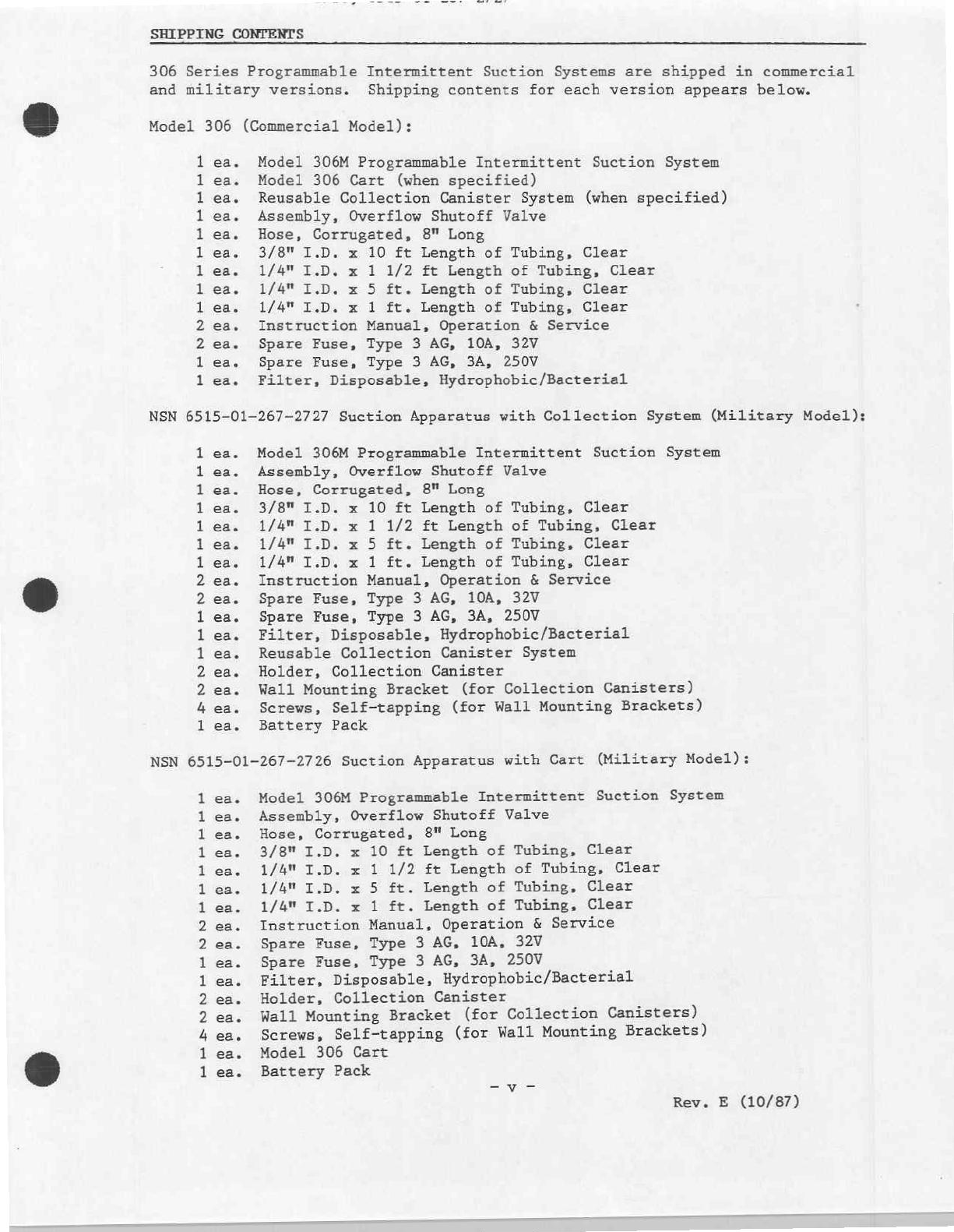
SHIPPING
CONTENTS
306
Series
Programmable
Intermittent
Suction Systems
are
shipped
in
commercial
and
military
versions.
Shipping
contents
for
each
version
appears
below.
Model
306
(Commercial
Model):
ea.
ea.
ea.
ea.
ea.
ea.
ea.
ea.
ea.
ea.
ea.
ea.
ea.
ビビ
ウゥ
らら
ビビ
ビビ
ビビ
ロロ
ビビ
ロビ
Model
306M
Programmable
Intermittent
Suction
System
Model
306
Cart
(when
specified)
Reusable
Collection
Canister
System
(when
specified)
Assembly,
Overflow
Shutoff
Valve
Hose,
Corrugated,
8"
Long
3/8"
I.D.
x
10
ft
Length
of
Tubing,
Clear
1/4"
1.D.
x
1
1/2
ft
Length
of
Tubing,
Clear
1/4"
Т.О.
х
5
ft.
Length
of
Tubing,
Clear
1/4"
I.D.
x
1
ft.
Length
of
Tubing,
Clear
Instruction
Manual,
Operation
&
Service
Spare
Fuse,
Type
3
AG,
10A,
32V
Spare
Fuse,
Type
3
AG,
3A,
250V
Filter,
Disposable,
Hydrophobic/Bacterial
NSN
6515-01-267-2727
Suction
Apparatus
with
Collection
System
(Military
Model):
ea.
ea.
ea.
ea.
ea.
ea.
ea.
ea.
ea.
ea.
ea.
ea.
ea.
ea.
ea.
ea.
O
Model
306M
Programmable
Intermittent
Suction
System
Assembly,
Overflow
Shutoff
Valve
Hose,
Corrugated,
8"
Long
3/8"
I.D.
x
10
ft
Length
of
Tubing,
Clear
1/4" I.D.
x
1
1/2
ft
Length
of
Tubing,
Clear
1/4" I.D.
x
5
ft.
Length
of
Tubing,
Clear
1/4"
I.D.
x
1
ft.
Length
of
Tubing,
Clear
Instruction
Manual,
Operation
&
Service
Spare
Fuse,
Type
3
AG,
10A,
32V
Spare
Fuse,
Type
3
AG,
3A,
250V
Filter,
Disposable,
Hydrophobic/Bacterial
Reusable
Collection
Canister
System
Holder,
Collection
Canister
Wall
Mounting
Bracket
(for
Collection
Canisters)
Screws,
Self-tapping
(for
Wall
Mounting
Brackets)
Battery
Pack
NSN
6515-01-267-2726
Suction
Apparatus
with
Cart
(Military
Model):
ea.
ea.
ea.
ea.
ea.
ea.
ea.
ea.
ea.
ea.
ea.
ea.
ea.
ea.
ea.
ea.
ロビ
よら
らい
ビ
ビ
い
らら
ロビ
ロビ
ビビ
ロビ
Model
306M
Programmable
Intermittent
Suction
System
Assembly,
Overflow
Shutoff
Valve
Hose,
Corrugated,
8"
Long
3/8"
I.D.
x
10
ft
Length
of
Tubing,
Clear
1/4"
I.D.
x
1
1/2
ft
Length
of
Tubing,
Clear
1/4"
I.D.
x
5
ft.
Length
of
Tubing,
Clear
1/4"
I.D.
x
1
ft.
Length
of
Tubing,
Clear
Instruction
Manual,
Operation
&
Service
Spare
Fuse,
Type
3
AG,
10A,
32V
Spare
Fuse,
Type
3
AG,
3A,
250V
Filter,
Disposable,
Hydrophobic/Bacterial
Holder,
Collection
Canister
Wall
Mounting
Bracket
(for
Collection
Canisters)
Screws,
Self-tapping
(for
Wall
Mounting
Brackets)
Model
306
Cart
Battery
Pack
Rev.
E
(10/87)
ας,
προς
ROE
ITE"
SI
ROS
SA
PN
ST
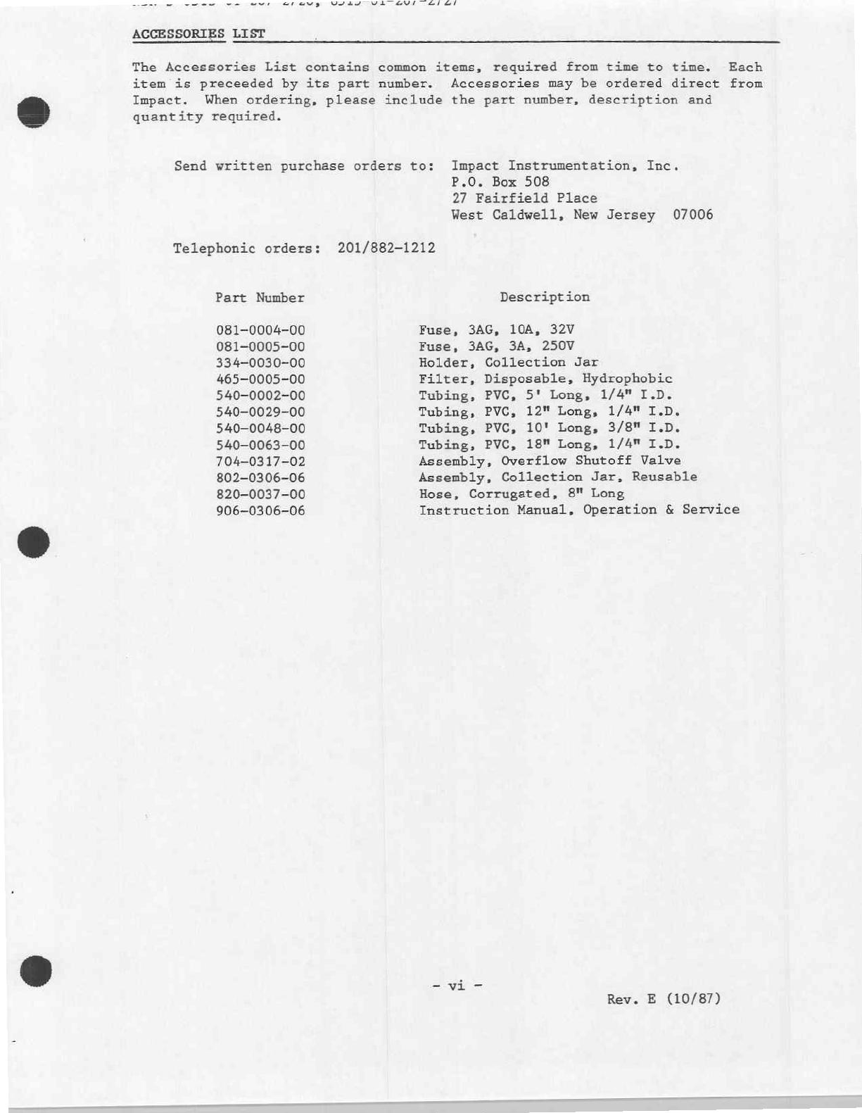
ACCESSORIES
LIST
The
Accessories
List
contains
common
items,
required
from time
to
time.
Each
item
is
preceeded
by
its
part
number.
Accessories
may
be
ordered
direct
from
Impact.
When
ordering,
please
include
the
part
number,
description
and
quantity
required.
Send
written
purchase
orders
to:
Impact
Instrumentation,
Inc.
P.O.
Box 508
27
Fairfield
Place
West
Caldwell,
New
Jersey
07006
Telephonic
orders:
201/882-1212
Part
Number
Description
081-0004-00
Fuse,
3AG,
10A,
32V
081-0005-00
Fuse,
3AG,
3A,
250V
334-0030-00
Holder,
Collection
Jar
465-0005-00
Filter,
Disposable,
Hydrophobic
540-0002-00
Tubing,
PVC,
5'
Long,
1/4"
I.D.
540-0029-00
Tubing,
PVC,
12"
Long,
1/4"
I.D.
540-0048-00
Tubing,
PVC,
10'
Long,
3/8"
I.D.
540-0063-00
Tubing,
PVC,
18"
Long,
1/4"
I.D.
704-0317-02
Assembly,
Overflow
Shutoff
Valve
802-0306-06
Assembly,
Collection
Jar,
Reusable
820-0037-00
Hose,
Corrugated,
8"
Long
906-0306-06
Instruction
Manual,
Operation
&
Service
-vi
-
Rev.
E
(10/87)
E
AN
A
ARE,
LIMITED
COPYRIGHT
RELEASE
Permission
is
hereby
granted
to
the
Department
of
Defense
to
reproduce
all
material
furnished
under
this
contract
for
use
in
a
military
service
training
program
and
other
technical
training
programs.
CALIBRATION
NOTICE
>
This
device
should
be
incorporated
into
a
regular
preventative
maintenance
program
to
insure
compliance
with
operating
specifications.
Calibration
measurements
should
be
made
on
a
biannual
basis
unless
significant
usage
warrants
a
shorter
period
between
preventative
maintenance
inspections.
A
calibration
check
should
be
made
following
each
cumulative
period
of
300
hours
of
operation.
Recommended
maintenance
checks
can
be
found
in
the
SERVICE
section
of
this
Manual.
UNPACKING
Check
the
contents
of
the
shipping
case(s)
against
the
enclosed
packing
list.
Examine
the
instrument
for
any
obvious
signs
of
shipping
damage.
If
there
is
no
apparent
sign
of
mechanical
damage,
read
the
instructions
contained
within
this
manual
before
attempting
to
operate
the
instrument.
LOCATION
OF
USE
2
The
Model
306/306M
is
a
portable
device,
therefore,
its
physical
area
of
use
will
vary.
When
operated
in
a
wet
environment,
user's
should
take
precautions
and
protect
this
device
by
covering
it
with
a
protective
barrier
(small
tarp,
plastic
sheet,
etc.).
WARNINGS
REGARDING
USE
This
equipment
is
intended
for
use
by
qualified
medical
personnel
only.
Danger
-
Possible
explosion
hazard
if
used
in
the
presence
of
flammable
anesthetics.
Caution
-
Electric
shock
hazard,
do
not
remove
instrument
covers.
Refer
servicing
to
qualified
service
personnel
only.
Do
not
operate
this
instrument
prior
to
reading
the
instructions
contained
within
this
manual.
Always
use
overflow
shutoff
valve
to
protect
pump
mechanism.
External
12VDC
Operation
—
Operate
only
from
diode
protected
external
12VDC
sources
when
simultaneous
AC
power
is
applied
(see
SERVICE
section
EXTERNAL
12VDC
OPERATION).
MILITARY
VERSIONS
-
DO
NOT
operate suction
apparatus
until
the
battery
pack
(shipped
separately)
is
installed.
Rev.
E
(10/87)
NSN's
6515-01-267-2726,
6515-01-267-2727
ASSEMBLY,
INTERGONNECTIONS
AND
INITIAL
ADJUSTMENTS
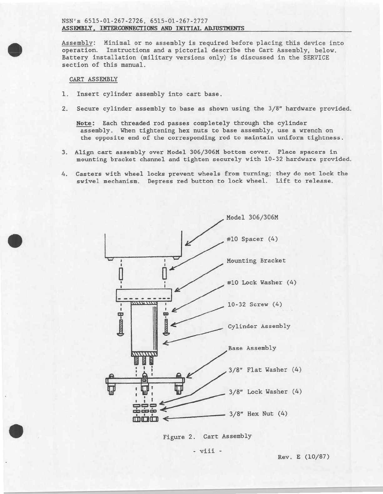
Assembly:
Minimal
or
no
assembly
is
reguired
before
placing
this
device
into
operation.
Instructions
and
a
pictorial
describe
the
Cart
Assembly,
below.
Battery
installation
(military
versions
only)
is
discussed
in
the
SERVICE
section
of
this
manual.
CART
ASSEMBLY
1.
Insert
cylinder
assembly
into
cart
base.
2.
Secure
cylinder
assembly
to
base
as
shown
using
the
3/8”
hardware
provided.
Note:
Each
threaded
rod
passes
completely
through
the
cylinder
assembly.
When
tightening
hex
nuts
to
base
assembly,
use
a
wrench
on
the
opposite
end
of
the
corresponding
rod
to
maintain
uniform
tightness.
3.
Align
cart
assembly
over
Model
306/306M
bottom
cover.
Place
spacers
in
mounting
bracket
channel
and
tighten
securely
with
10-32
hardware
provided.
4.
Casters
with
wheel
locks
prevent
wheels
from
turning;
they
do
not
lock
the
swivel
mechanism.
Depress
red
button
to
lock
wheel.
Lift
to
release.
Model
306/306M
#10
Spacer
(4)
Mounting
Bracket
AI
a
o
#10
Lock
Washer
(4)
ビー
ニー
で
ここ
oe
10-32
Screw
(4)
Cylinder
Assembly
(24
--
Base
Assembly
3/8"
Flat
Washer
(4)
de
3/8"
Lock
Washer
(4)
“na
ce
3/8"
Hex
Nut
(4)
Figure
2.
Cart
Assembly
-
viii
-
Rev.
E
(10/87)
NSN's
6515-01-267-2726,
6515-01-267-2727
ASSEMBLY,
INTERCONNECTIONS
AND
INITIAL
ADJUSTMENTS
(cont'd)
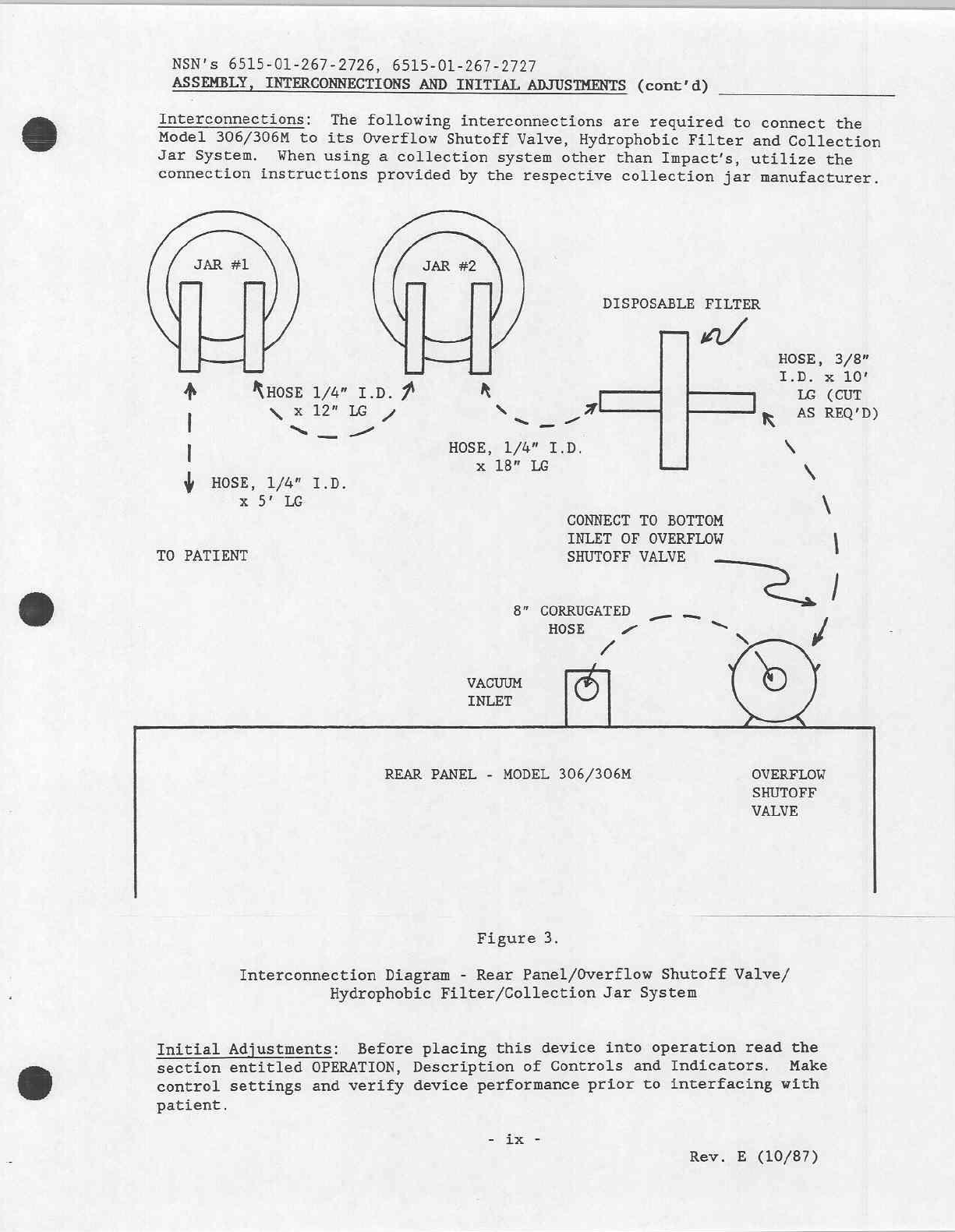
Interconnections:
The
following
interconnections
are
required
to
connect
the
Model
306/306M
to
its
Overflow
Shutoff
Valve,
Hydrophobic
Filter
and
Collection
Jar
System.
When
using
a
collection
system
other
than
Impact's,
utilize
the
connection
instructions
provided
by
the
respective
collection
jar
manufacturer.
DISPOSABLE
FILTER
asi
ca
HOSE,
3/8”
I.D.
x
10!
4
KHOSE
1/4"
I.D.
À
R
可
=
LG
(CUT
x
12"
LG
N
,
|
NE
Ea
aio
R
45
REQ'D)
|
E
HOSE,
1/4"
I.D.
x
x
18"
LG
X
Ý
HOSE,
1/4"
I.D.
x
9°
LG
N
CONNECT
TO
BOTTOM
INLET
OF
OVERFLOW
|
TO
PATIENT
SHUTOFF
VALVE
νι
η
8”
CORRUGATED
__
_
HOSE
à
=
и
и
N
/
VACUUM
INLET
©
REAR
PANEL
-
MODEL
306/306M
OVERFLOW
SHUTOFF
VALVE
Figure
3.
Interconnection
Diagram
-
Rear
Panel/Overflow
Shutoff
Valve/
Hydrophobic
Filter/Collection
Jar
System
Initial
Adjustments:
Before
placing
this
device
into
operation
read
the
section
entitled
OPERATION,
Description
of
Controls
and
Indicators.
Make
control
settings
and
verify
device
performance
prior
to
interfacing
with
patient.
-
ix
-
Rev.
E
(10/87)

ーー
-~
veste
va
GUI
TAI
LUS,
OD13-U1-20/—2/2/
SECTION
I.
OPERATION
INTRODUCTION
The
Model
306M
Programmable
Intermittent
Suction
System
represents
the
state
of
the
art
in
portable
suction
apparatus.
This
device
will
provide
years
of
reliable
service
when used
in
accordance
with
the
instructions
contained
within
this
manual.
The
following
text
highlights
several
of
its
key
features.
Electronic
Vacuum
Regulator
-
This
circuit
differs
from
conventional
mechanical
regulators
in
several
ways.
First,
the
regulator
is
eliminated
from
the
vacuum
path
and,
therefore,
cannot
leak,
clog,
jam
or
stick.
Second,
the
regulator
is
energy
efficient;
it
only
draws
current
proportional
to
the
amount
of
vacuum
you
require.
Third,
the
regulator
can
precisely
select
vacuum
levels
with
micrometer
precision
for
your
most
critical
suction
needs.
Electronic
Intermittent
Suction
Circuits
-
These
circuits
determine
ON
and OFF
times,
selectable
in
144
different
combinations.
The OFF
circuit
shuts
dow
virtually
the
entire
unit
during
its
time
period
thereby
maximizing
energy
efficiency.
The
ON
circuit
immediately
energizes
the
system
for
prompt
response.
Emergency
Battery
-
A
sealed
lead-acid
(GEL
Cell)
battery
is
provided
for
emergency
and
transitory
use.
Its
operating
time
varies
depending
upon
the
vacuum
levels
drawn.
With
this
in
mind,
a
high
capacity
battery
was
chosen
which
can
provide
over
one
hour
of
continuous
use
at
maximum
vacuum
(550
mm/hg).
At
200
mm/hg
cycled
intermittently
at
5
seconds
ON
and
5
seconds
OFF,
the
battery
will
provide
more
than
twelve
hours
continuous
use.
Because
this
battery
is
not
considered
the
primary
power
source,
its
use
should
be
restricted
to
emergencies
and
transport
to
insure
available
power.
OPERATION
Description
of
Controls
and
Indicators
Refer
to
the
reference
pictorial
on
the
following
page.
Numbers
contained
within
this text
(in
parentheses)
correspond
to
the
numbers
indicated
in
the
pictorial.
(1)
Master
Power
Switch
(7)
Vacuum
Regulator
Power
Lamp
(2)
Master
Power
Indicator
Lamp
(8)
Vacuum
Gauge
(3)
Power
Mode
Switch
(9)
On
Time
Selector
Switch
(4)
Suction
Mode
Switch
(10)
Off
Time
Selector
Switch
(5)
Suction
Level
Switch
(11)
Fuse,
3A,
250V,
3AG
(6)
Vacuum
ON/OFF/ADJ
Switch
(12)
Fuse,
10A,
32V,
3AG
aaah
Rev.
E
(10/87)
мым
©
VY4JTVLTE0/74/
20,
BDL5-UV1—26/—2/2/
(1)
(4)
G)
(6)
(7)
(8) (9)
(11)
(5)
(12)
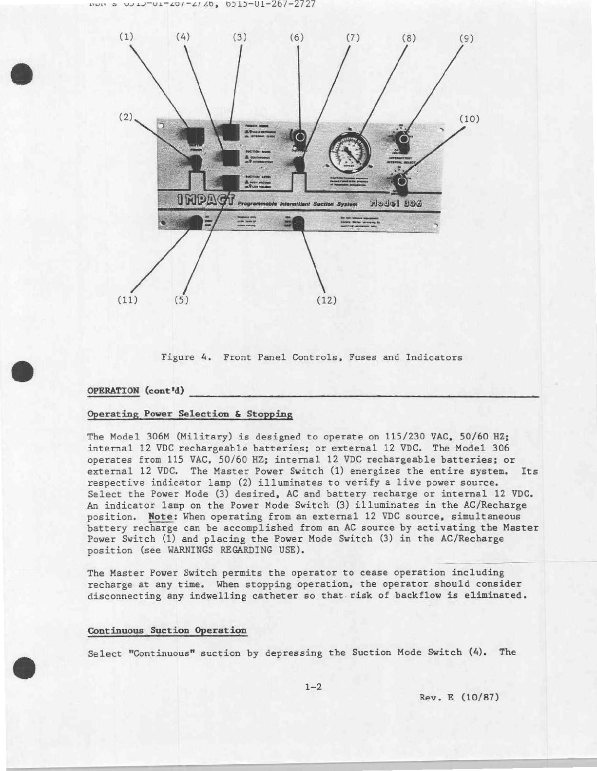
Figure
4.
Front
Panel
Controls,
Fuses
and
Indicators
OPERATION
(cont'd)
Operating
Power
Selection
&
Stopping
The
Model
306M
(Military)
is
designed
to
operate
on
115/230
VAC,
50/60
HZ;
internal
12
VDC
rechargeable
batteries;
or
external
12
VDC.
The
Model
306
operates
from
115
VAC,
50/60
HZ;
internal
12
VDC
rechargeable
batteries;
or
external
12
VDC.
The
Master
Power
Switch
(1)
energizes
the
entire
system.
Its
respective
indicator
lamp
(2)
illuminates
to
verify
a
live power
source.
Select
the
Power
Mode
(3)
desired,
AC
and
battery
recharge
or
internal
12
VDC.
An
indicator
lamp
on
the
Power Mode
Switch
(3)
illuminates
in
the
AC/Recharge
position.
Note:
When
operating
from
an
external
12
VDC
source,
simultaneous
battery
recharge
can
be
accomplished
from
an
AC
source
by
activating
the
Master
Power
Switch
(1)
and
placing
the
Power Mode Switch
(3)
in
the
AC/Recharge
position
(see
WARNINGS
REGARDING
USE).
The
Master
Power Switch
permits
the
operator
to
cease
operation
including
recharge
at
any
time.
When
stopping
operation,
the
operator
should
consider
disconnecting
any
indwelling
catheter
so
that.
risk
of
backflow
is
eliminated.
Continuous
Suction
Operation
Select
"Continuous"
suction
by
depressing
the
Suction
Mode
Switch
(4).
The
1-2
Rev.
E
(10/87)

NSN's
0515-01-207-2726,
6515
OPERATION
(cont'd)
indicator
lamp
for
this
switch
will
not
illuminate
in
this
mode.
.
The
Suction
Level
Switch
(5)
selects
two
operating
limits
for
vacuum;
0-200
mm/hg
(Low
Vacuum),
or
0-550
mm/hg
(High
Vacuum).
An
indicator
lamp
illuminates
when
Low
Vacuum
is
selected.
To
operate
the
Electronic
Vacuum
Regulator
(EVR),
turn
the
control
(6)
clockwise
to
its
"ON"
position
and
continue
rotating
it
to
the
desired
vacuum
level.
Preselecting
the
desired
vacuum
limit
can
be
accomplished
by
blocking
the
free
flow
of
air
through
the
system.
Allow
air
to
evacuate
from
any
collection
jar
system
when
preselecting
the
vacuum
limit,
Remember
that
the
maximum
vacuum
limit
is
regulated
by
the
Suction
Level
Switch
(5).
The
EVR
indicator
lamp
(7)
will
remain
on
until
the
EVR
Control
Switch
(6)
is
"clicked
off"
by
turning
fully
counterclockwise.
Vacuum
readings
may
be
read
directly
from
the
front
panel
Vacuum
Gauge
(8).
Intermittent
Suction
Operation
The
Suction
Mode
and
Suction
Level
Switches
(4,
5)
must
be
depressed
and
illuminated
for
intermittent
operation.
To
prevent
dangerous
high
vacuum
levels
from
appearing
at
the
pump
output
during
intermittent
suctioning,
a
safety
lockout
allows
this
mode
to
operate
in
the
Low
Vacuum
Level
range
only.
After
preselecting
the
desired
vacuum
level
as
described
in
the
previous
section,
the
ON
(9)
and
OFF
(10)
time
suction
circuits
may
be
set
to
the
desired
range.
Each
circuit
is
programmable
in 12
increments
of
5
seconds
each.
A
total
of
144
programmable
combinations
are
available
to
"custom
tailor"
the
Model
306M
to
your
patient's
needs.
Electronic
Vacuum
Regulator
The
EVR
(6)
works
in
conjunction
with
the
Suction
Level
Switch
(5).
Precise
vacuum
levels
may
be
selected
with
extreme
accuracy
for
most
procedures.
Variability
from
0-200
mm/hg
and
0-550
mm/hg
adds
additional
versatility
and
power
when
needed
for
emergencies
or
surgical
applications.
The
EVR
is an
energy
efficient
circuit,
drawing
only
an
amount
of
current
proportional
to
the
level
of
vacuum
desired.
Unlike
conventional
regulators
which
"bleed"
an
efficient
system
running
at
full
power,
the
EVR
runs
at
lower
speeds
unless
full
power
is
required.
Collection
Jar
System
ALWAYS
use the
Overflow
Shutoff
Valve
provided
with
this unit
to
protect
the
suction
mechanism
from
overflows
which
may
permanently
damage
the
vacuum
pump.
Vacuum
tubing
is
provided
for
interconnection
of
Collection
Jars,
Hydrophobic
Filter,
Overflow
Shutoff
Valve
and
rear
panel
barbed
hose
inlet
(see
Figure
3).
A
disposable
filter
which
is
both
hydrophobic
and
bacterial
is
provided.
This
filter
connects
between
the
Overflow
Shutoff
Valve
and
final
collection
jar.
This
filter
should
be
replaced
when
discoloration
of
its
membrane
occurs,
the
membrane
contacts
aspirate,
or
following
150
cumulative
hours
of
use.
This
filter
is
designed
to
retain
bacteria
which
would
otherwise
be
exhausted
into
the
immediate vicinity.
DO
NOT
bypass
this
filter.
1-3
Rev.
E
(10/87)
NSN's
6515-01-20
OPERATION
(cont
'd)
Operator Performance
Checks
Before
placing
this
device
into
operation,
the
operator
can
perform
various
operational
checks
to
insure
proper
performance.
1.
Verify
operating
power
selections
at
115
or
230
VAC,
internal
rechargeable
batteries
and
external
12
VDC.
2.
Verify
continuous
operation
at
both
high
and
low
ranges,
in
each
of
the
operating
power
modes.
3.
Verify
that
intermittent
suction
operates
only
in
the
low
vacuum
range
in
each
of
the
operating
power
modes.
4.
Test
the
Electronic
Vacuum
Regulator
by
adjusting
vacuum
in
the
high
and
low
ranges,
in
each
of
the
operating
power
modes.
1-4
Rev.
E
(10/87)

WOINTS
ODLITYUINL0/—
2/20,
OD19-01-20/—4/427
BATTERY
CARE
The
Model
306/306M
utilizes
sealed
GEL
Cell
batteries
which offer
excellent
charge
retention
characteristics,
particularly
during
long
periods
of
storage.
This
ensures
an
ample
amount
of
power
during
emergencies
and
transitory
procedures.
The
battery
pack
in
this
device
is
not
intended
for
routine,
day-
to-day
use,
therefore,
it
should
be
used with
discretion
and
its
design
understood.
To
provide
long
life
and
maximum
performance
capabilities,
the
Model
306M
requires
sixteen
hours
to
fully
recharge
its
fully
discharged
batteries.
Of
course,
the
batteries
are
rarely
discharged
this
much
so
the
subsequent
recharge
time
is
usually
less.
GEL
Cell
batteries
require
little
user
care
to
provide
optimum
performance
and
life
expectancy.
Because
their
self-discharge
rate
is
extremely
low
(approximately
1-1/2%
per
month),
lengthy
periods
of
disuse
without
replenishment
charging
is
possible.
The
life
of
these
batteries
depends
to
a
great
extent
upon
the
care
they
receive.
Following
these
simple
guidelines
will
prevent
premature
charge
depletion
and
reduction
of
battery
life.
1.
DO
NOT
operate
this unit
where
the
temperature
range
exceeds
-60°C
to
60°C
(-76°F
to
140°F).
2.
DO
NOT
charge
this unit
where
the
temperature
range
exceeds
-20°C
to
50°C
(-4°F
to
122°F).
3.
DO
NOT
store
this
unit
with
the
batteries
discharged.
Always
store
in
a
charged
condition.
4.
For
long-term
storage,
the
optimum
temperature
range
is
10°C
to
30°C (50°F
to
80°F).
Recharging
Batteries
Ensure
that
the
AC
line
cord
is
connected
to
a
3-wire,
grounded
outlet.
Turn
the
Master
Power
Switch
(1)
ON
and
verify
that
the
Master
Power
Indicator
Lamp
(2)
illuminates.
Depress
the
Power
Mode
Switch
(3)
to
the
"AC
and
Recharge"
position.
Its
built-in
lamp
will
illuminate.
Verify
that
the
Vacuum
ON/OFF/ADJ
Switch
(6)
is
"clicked"
off and
its
respective
indicator
(7)
is
unlit.
The
unit
is
now
in
a
recharge
state.
During
normal
AC
operation,
a
charging
current
automatically
flows
into
the
batteries
keeping
them
replenished
while
normal
operating
power
requirements
are
met.
Rev.
E
(10/87)
やら
>
VJYLJTV1T60/T4/
40,
0515-01-26/-2
ROUTINE
CARE
AND
MAINTENANCE
Cleaning
Periodically
or
when
applicable,
clean
the
exterior
case
using
mild,
non-
abrasive
cleansers.
DO
NOT
allow
liquids
to
enter
the
control
system;
a
damp
cloth
will,
in
most
cases,
suffice.
Disinfectant
spraying
is
recommended
at
regular
intervals.
Collection
jar
systems
should
be
cleaned
or
disposed
of
in
accordance
with
their
respective
instructions.
Impact's
reusable
collection
jar,
its
cover
and
hose
connectors
may
be
autoclaved.
Maintenance
Routine
maintenance
should
be
performed
on
this
apparatus
at
regular
intervals
and
prior
to
being
placed
into
service.
Routine
maintenance
should
consist
of
the
following:
1.
Cleaning
checks
-
as
described
above.
2.
Filter
checks
-
replace
when
discolored,
contact
with
aspirate
occurs,
airflow
performance
diminishes
considerably
or
following
150
hours
of
cumulative
use.
3.
Overflow
shutoff
valve
-
clean
in
warm,
soapy
water
or
with
a
mild
disinfectant
solution
when
contacted
with
aspirate
or
following
150
hours
of
cumulative
use.
Dry
thoroughly
before
reassembling.
4.
Operational
checks
-
as
described
in
Operator
Performance
Checks.
5.
Tubing
checks
-
replace
crimped,
cracked
or
worn
tubing
as
required.
6.
Cart
checks
-
verify
smooth
turning
of
casters
and
operation
of
locks.
Replace
worn
casters.
Rev.
E
(10/87)
NSN's
6515-01-267-2720,
0515-01-267-2727
IN
CASE
OF
DIFFICULTY
Authorization
to
service
this
instrument
by
other
than
factory-trained
and
certified
personnel
will
not
be
given,
nor
does
Impact
Instrumentation,
Inc.
assume
any
responsibility
and/or
liability resulting
from
such
unauthorized
servicing.
Impact
will,
upon
request,
provide
competent
biomedical
engineering
departments
with
service
data
and
schematics.
Such
departments
are
encouraged
to
contact
the
factory
for
assistance
when
needed
and
it
is
recommended
that
staff
members
attend
a
factory
training
course.
Details
may
be
obtained
by
contacting
the
Impact
Customer
Service
Department.
Operator
Correctible
Problems
Common
problems
may
be
quickly
rectified
by
users.
Should
the
Model
306/306M
fail
to
operate
properly,
verify
the
integrity
of
all
tube
connections,
tubing,
fittings,
and
control
settings.
One
can
quickly
isolate
problems
to
an
accessory
item
or
the
control
unit
by
testing
for
vacuum
at
various
locations.
To
isolate
a
problem,
check
for
vacuum
at
the
inlet
of
each
item,
tracing
backwards
through
the
system,
i.e.:
vacuum
from
jar
#1
to
jar
#2,
vacuum
from
the
filter
to
jar
#1,
vacuum
from
the
Overflow
Shutoff
Valve
to
the
filter,
vacuum
from
the
rear
panel
vacuum
port
to
the
Overflow
Shutoff
Valve.
Operator
Problems
Requiring
Service
If
the
tests
described
above
do
not
resolve
an
operating
problem,
service
is
required.
Should
servicing
be
necessary,
contact
your
nearest
Impact
representative
or
the
Impact
Customer
Service
Department
(201)
882-1212.
Please
have
the
Model
and
Serial
Numbers
ready
and
any
other
pertinent
data
you
wish
to
include
in
your
service
request.
The
Model
306/306M
Serial
Number
is
located
on
the
Rear
Panel
identification
label.
Rev.
E
(10/87)
wen's
09212-01-20/-2/26,
6515-01-20
STORAGE
INFORMATION
For
prolonged
storage
periods,
the
Model
306/306M
should
be
stored
indoors.
The
environment
should
be
clean,
and
out
of
direct
sunlight.
Storage
temperature
range
should
be
within
5°
to
104°F
(-15°
to
40°C),
humidity
should
be
low.
When
batteries
are
in
extended
storage,
it
is
recommended
that
they
receive
a
refresh
charge
at
recommended
intervals:
Storage Ambient
Recharge
Interval
below
68°F
(20°C)
18
months
68°
to
86°F
(20°
to
30°C)
12
months
86°
to
104°F
(30°
to
40°C)
6
months
LIMITED
WARRANTY
Impact
Instrumentation,
Inc.
warrants
this
instrument
to be
free from
all
defects
in
materials
and
workmanship
for
a
period
of
one
(1)
year.
Batteries,
which
by
their
nature
are
consumable
and
subjected
to
environmental
extremes,
will
be
warranted
only
for
defects
of
manufacturing
origin
for
a
period
of
ninety
(90)
days.
This
warranty
is
neither
assignable
nor
transferable,
nor
does
it
apply
if
this
instrument
is
tampered
with,
misused
or
serviced
by
unauthorized
personnel.
Rev.
E
(10/87)

em:
UDIITUI=40/=2/70,
6515-01-207-2727
SPECIFICATIONS
Vacuum
Range:
Continuous:
Low:
High:
Intermittent:
Free
Airflow
Range:
Temperature
Operating
Range:
Power:
External:
Internal:
Operating
Time:
Recharge
Time:
Controls:
Master
Power:
Power
Mode:
Suction
Mode:
Suction
Level:
Suction:
On
Interval
Select:
Off
Interval
Select:
Indicators:
Case:
Size:
Weight:
Cart:
Size:
Weight:
O
-
200
mm/Hg,
+/-
25
mmHg
(0
-
8"
Hg,
+/-
1"
Hg)
0
-
550
mm/Hg,
+/-
50
mmHg
(0
-
22"
Hg,
+/-
2"
Hg)
O -
200
mm/Hg,
+/-
25
mmig
(0
—
8"
Hg,
+/-
1"
Hg)
24
-
35
Liters
Per
Minute
(LPM)
-60°C
to
60°C
(-76°F
to
140°F)
115/230
VAC,
50/60
HZ;
12
VDC
12
VDC
(Rechargeable
Batteries)
1
Hour
at
maximum
vacuum
(typical)
16
Hours
(typical)
ON/OFF
AC
&
Recharge/Internal
12
VDC
Continuous/Intermittent
High
Vacuum/Low
Vacuum
ON/OFF
/ADJUST
5
-
60
seconds
in
5
second
increments
5
-
60
seconds
in
5
second
increments
Master
Power
Lamp
AC
&
Recharge
Lamp
Intermittent
Suction
Mode
Lamp
Low
Vacuum
Level
Lamp
Suction
"ON"
Lamp
Vacuum
Gauge
-
Dual
Scale,
Metric/English
Aluminum,
Epoxy
Paint
Combination
46cm
W
x
18cm
H x
25cm
D
(18"
W
x
7"
H x
10"
D)
11
KG
(25
lbs.)
46cm
W x
46cm
D x
75cm
H
(18"
W x
18"
D
x
30"
H)
11
Кб
(25
lbs.)
Specifications
contained
herein
represent
typical
device
performance.
Impact
Instrumentation,
Inc.
reserves
the
right
to
change
these
specifications
without
prior
notification.
Rev.
E
(10/87)

NSN's
0515-Ui-20/-2/20,
SECTION
II.
SERVICE
INTRODUCTION
The
information
contained
herein
is
intended
only
for use
by
factory-trained,
and
certified personnel
or
military
personnel
trained
in
the
care
and
servicing
of
this
product.
The
manufacturer
does
not
authorize
or
assume
any
obligations
resulting
from
unauthorized
servicing
nor
will
it
be
held
liable
for
any
injuries
or
damages
incurred
therefrom.
Impact
Instrumentation
will
provide
service
training
at
the
manufacturing
site
at
no
schooling
charge
to
users;
however,
travel
and
meal
costs
resulting
therefrom
shall
be
borne
by
the
user.
Training
at
the
user's
site
will
result
in
travel,
meal
and
time
costs
charged
to
the
user
at
prevailing
rates.
The
Impact
service
facility
encourages
dialogue
from
user
service
personnel
towards
rectifying
any
service
related
matter.
All
service
requests
may
be
addressed
to
the
Service
Manager,
Impact
Instrumentation,
Inc.,
27
Fairfield
Place,
West
Caldwell,
New
Jersey
07006,
201/882-1212.
CAUTIONARY
NOTES
External,
12VDC
Operation
Warning:
If
simultaneous
AC
recharging
and
external
12VDC
operation
is
employed,
insure
that
the
external
12VDC
source
is
diode
protected
against
potentially
high
currents.
This
warning
does
not
apply
for
independent
operation
from
an
external
12VDC
source.
Internal
Rechargeable
Battery
Military
versions
of
this
product
are
shipped
with
batteries
in
separate
cartons.
Prior
to
placing
this
device
into
operation,
the
battery
pack must
be
installed.
Do
not
operate
this
unit
until
battery
pack
is
installed.
HELPFUL
HINTS
Before
attempting
to
repair/calibrate
this
instrument,
please
take
a
few
moments
to
insure
that
the
problem
is
not
accessory
related.
Check
the
integrity
of
all
vacuum
hoses
and
tubing.
Verify
that
the
tubing
has
no
crimps
or
cuts
in
it.
Insure
that
all
collection
jars
seal
properly.
Insure
that
overflow
shut-off
valves
do
not
stick.
Refer
to
the
enclosed
schematics
and
assembly
drawings
when
electrically
troubleshooting.
Isolate
the
problem
to
a
functional
segment
of
the
circuitry.
Always
insure
the
integrity
of
circuit
ground
and
the
correct
power
supply
voltages.
Always
safeguard
your
personal
well
being
when
troubleshooting
electronic
circuitry.
Keep
jewelry
and
liquids
from
the
vicinity
of
active
circuitry.
JET
Rev.
E
(10/87)
This manual suits for next models
1
Table of contents
Other Impact Instrumentation Batteries Pack manuals


