GREEN BANK WG48350 User manual

WG48350 Battery System for HouseholdsWG48350 Battery System for Households358-010245-00

1 ABOUT THIS MANUAL ..................................................................................... 1 1.1 Purpose ................................................................................................. 1 1.2 Scope .................................................................................................... 1 1.3 Safety Instructions .................................................................................. 12 INTRODUCTION .............................................................................................. 2 2.1 Features................................................................................................. 2 2.2 Product Overview ................................................................................... 2 2.3 Specifications ........................................................................................ 4 2.4 Recommended Settings .......................................................................... 43. INSTALLATION ............................................................................................... 5 3.1 Unpacking and Inspection ....................................................................... 5 3.2 Mounting the Unit ................................................................................... 5 3.3 Connection for Parallel Mode ................................................................... 54. OPERATION ................................................................................................... 7 4.1 Switch On/Off.......................................................................................... 7 4.2 Description for LED ................................................................................. 7 4.3 ON / OFF or SOC Led (Mode or SOC) ....................................................... 8 4.4 DIP switch SW1-SW4 Description ............................................................ 85. EMERGENCY SITUATIONS ............................................................................. 9 5.1 Fire ...................................................................................................... 9 5.2 Leaking Batteries .................................................................................. 9 5.3 Wet Batteries ........................................................................................ 9 5.4 Warranty .............................................................................................. 9Contents

0102LiFePO4 Battery System for HouseholdsLiFePO4 Battery System for Households2. INTRODUCTIONThe battery system main using Solar power system for Family house. It also have a with to controller the battery easily and protect our Household application timely.• Iron phosphate-lithium power battery • Long warranty period:5 years• Higher energy density, smaller volumn for household.• Support connected in parallel mode for expansion• Photovoltaic system: This battery pack is designed for household photovoltaic systems.• Battery management system (BMS): The battery packs built-in BMS monitors its operation and prevents the battery from operating outside design limitations.• Expandability: This battery pack can be easily expanded by adding expansion battery packs in parallel connection.2.2 Product Over View2.1 Features1.1 PurposeThis manual describes the introduction, installation, operation and emergency situations of the battery bank. Please read this manual carefully before installations and operations. Keep this manual for future reference.1.2 ScopeThis manual provides safety and installation guidelines as well as information on tools and wiring.1.3 Safety Instructions WARNING: This chapter contains important safety and operating instructions. Read and keep this manual for future reference.1.Before using the unit, read all instructions and cautionary markings on the unit, the batteries and all appropriate sections of this manual.2. CAUTION –,even burst. please use it following using manual. In case -- To reduce risk of injury,damage of causing personal 3. Do not disassemble the battery. Take it to a qualified service center when service or repair is required. Incorrect re-assembly may result in a risk of fire.4. To reduce risk of electric shock, disconnect all wirings before attempting any maintenance or cleaning. Turning off the unit will not reduce this risk.5. CAUTION – Only qualified personnel can install this device with inverter.6. For optimum operation of this battery, please follow required spec to select appropriate cable size. 7. Be very cautious when working with metal tools on or around batteries. A potential risk exists to drop a tool to spark or short circuit batteries or other electrical parts and could cause an explosion or fire.8. Please strictly follow installation procedure.9. To support full output load, at least 2 sets of WG48350 for inverter larger than 6KVA in parallel connection.10. GROUNDING INSTRUCTIONS - This System should be connected to a permanent grounded wiring system. Be sure to comply with local requirements.11. NEVER cause AC output and DC input short circuited. Do not connect to the mains when DC input short circuits.12. Warning!! Only qualified service persons are able to service this device.13. Battery should be installed indoor and kept away from water, high temperature mechanical force and flames.14. Do not install the battery in any environment of temperature below 0°C or over 55°C,and humidity over 80%.15. Do not put any heavy objects on the battery.1 ABOUT THIS MANUALSpecial Attention: Due to the built-in protection board of the lithium battery pack is with over-discharge protection function, it is strongly recommended to stop using the load when the battery pack is over-discharged. The battery pack cannot be repeatedly activated for discharge. Or the battery may be failed to be activated by the AC or PV activation cable ( It requires a special charging activation method), so cannot be charged. Therefore, when the battery pack is low power, please charge the battery as soon as possible when main power or solar energy is available.1. The batteries can be connected in parallel. Series connection is not allowed. Use in upright position only.2. The batteries are not allowed to connected with PWM controller for charging.1.4 Can be connected in parallel

LiFePO4 Battery System for HouseholdsLiFePO4 Battery System for Households2.4 Recommended SettingsLithium battery pack is not same as lead-acid battery, so for the devices which you connect with the battery pack for charging or discharging, such as inverters, MPPT charger controllers or UPS, please implement pre-settings as recommended settings as below before you launched them.Setting Max. Charging Voltage Floating charging VoltageMax. Charging CurrentCut-off voltageNotes: “N” means the number of battery packs connected in parallel.2.3 Specifications030457.6V57.6V48V120A*N ModelUsable CapacityNominal VoltageVoltage RangeMAX. Charge & Discharge CurrentRecommend Charge & Discharge CurrentMAX. Output PowerRecommend Output PowerDODModules ConnectionCommunicationIngress ProtectionCycle LifeWorking Temperature RangeNet Weight(KG) Gross Weight(KG)Product Dimension(MM)Package Dimension(MM)≥95%1~6in parallelCAN&RS485IP21 ≥6000@25°C , 80%DOD Discharge:-20°C to +65°C, Charge:+0°C to +55°C WG4835015KWH51.248-57.6≤120A 10000W6000W200A@15SWG48350
715x450x1115MM177KG154KG615x350x955MM
1. LED display 2. Power On/Charging indicator 3.Battery Negative - 4. Battery Positive + 5. Switch 6. Communication port7.Earth wire 8. Breaker 65743812Total capacity16.8KWH

LiFePO4 Battery System for HouseholdsLiFePO4 Battery System for Households0605Before installation, please inspect the unit. Be sure that nothing inside the package is damaged. You should have received the following items inside of package.3.1 Unpacking and Inspection3. INSTALLATION3.2 Mounting the UnitConsider the following points before selecting where to install:• Do not mount the battery on flammable construction materials.• The ambient temperature should be between 0°C and 45°C to ensure optimal operation.• The recommended installation position is to be adhered to the wall vertically.• Be sure to keep other objects and surfaces as shown in the right diagram to guarantee sufficient heat dissipation and to have enough space for removing wires.Please follow below steps to implement battery connection:1.Assemble battery ring terminal based on recommended battery cable and terminal size.2.Connect all battery packs as units requires. It’s suggested to connect at least 2 sets of WG48350 for inverter larger than 6KVA in parallel connection.Note: if you need the battery wake-up when the grid back, connect the battery with grid use power adapter and communication line 1 shown in the package list.The WG48350 series battery support to be connected in parallel for expansion. If you need one more battery bank work in parallel mode, connect the battery as shown in PIC 1.3.3 Connection for Parallel ModeNO NAME SPECIFICATION PICTURECommunication line 1 Communication line 2 Used for Communication among batteriesCables Used for battery parallel connectionAdapter PV Wake up line User manual User manualGuarantee card Guarantee card 513452216Grid activation communication wire ( used with 6) Used for activating the pack when gridpower recover 7Used for auto restart when PV comeback in off-grid system8463Communication line 3 Used for communication between battery and host computer
8
Main Circuit
Note:After completing the above steps, arbitrarily select the positive and negative poles of one of the battery packs to output. After confirming the correct connection of the inverter, controller and battery, you can turn on any of the switches and use the battery group happily.
Step 1: The schematic diagram of the parallel connection of three battery packs is shown in Figure 1.For pure off grid system ,the PV awake wire need to be connected with MPPT charge controller if the battery pack is charged by solar panels only . The connection diagram as below :7

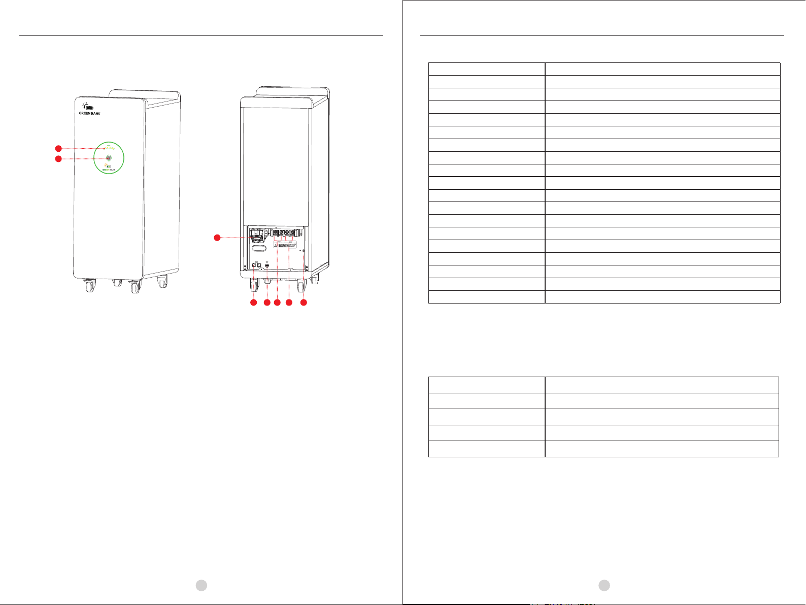
08LiFePO4 Battery System for Households07LiFePO4 Battery System for Households4. OPERATIONOnce the batteries are connected well, close the breaker to the ON block, press On/Off button to enable the output of the battery pack.Note: The battery need to be fully charged for at least once in one month to ensure the accurate SOC calculation.1.Switch on: press On/Off button to switch on the battery, then the battery will do self-inspection before enable output. The LED will show the SOC.2.Switch off: press and hold On/Off button for 3 seconds, the battery will shut down directly. Description for Communication port4.1 Switch On / OffPicture PIN Description12345678Trigger-GNDTrigger-VCCNCCOMM-GNDRS485-BRS485-ACANLCANHThe SOC of the battery is shown by the LED4.2 Description for LEDDIP SWITCH1-45Communication AddressTermination Resister100% 75% 50% 25% Flashing SOC<10%4.3 ON / OFF or SOC Led (Mode or SOC)BATTERY MODEON/OFFSOCREMARKGREEN LEDRED LED LED1 LED2 LED3 LED4 POWER OFFOFFOFFOFFOFFOFFOFFPOWER ONOFFONONONONONSTANDBYOFFOFFSOCSOC<10%(DEFAULT): LED1 FLASHNORMALONOFFRUNNING/SOCSOC<10%(DEFAULT): LED1 FLASHDISCHARGEONOFFSOCSOC<10%(DEFAULT): LED1 FLASHCHARGEFLASHOFFRUNNINGLOW POWERFLASHOFFOFFFAULTOFFONONOFFOFFOFFBATTERY VOLTAGE HIGHOFFONOFFOFFBATTERY VOLTAGE LOWONONOFFOFFCELL VOLTAGE HIGHOFFOFFONOFFCELL VOLTAGE LOWONOFFONOFFCHARGING CURRENT HIGHOFFONONOFFDISCHARGING CURRENT HIGHONONONOFFBMS TEMPERATURE HIGHOFFOFFOFFONBMS TEMPERATURE LOWONOFFOFFONCELL TEMPERATURE HIGHOFFONOFFONCELL TEMPERATURE LOWONONOFFONCURRENT SENSOR ABNOMALSw1 SW2 SW3 SW4 Remarks 0 0 0 0 means ID=0,communication address is0x00/0x10③ 1 0 0 0 means ID=1,communication address is0x01④ 0 1 0 0 means ID=2,communication address is0x02 1 1 0 0 means ID=3,communication address is0x03 0 0 1 0 means ID=4,communication address is0x04 1 0 1 0 means ID=5,communication address is0x05 0 1 1 0 means ID=6,communication address is0x06 1 1 1 0 means ID=7,communication address is0x07 0 0 0 1 means ID=8,communication address is0x08 1 0 0 1 means ID=9,communication address is0x09 0 1 0 1 means ID=10,communication address is0x0A 1 1 0 1 means ID=11,communication address is0x0B 0 0 1 1 means ID=12,communication address is0x0C 1 0 1 1 means ID=13,communication address is0x0D 0 1 1 1 means ID=14,communication address is0x0E 1 1 1 1 means ID=15,communication address is0x0FDIP switch SW5 Description②SW5 1 0Remarksmeans disconnect 120Ω resistormeans connect 120Ω resistorRemark①: 1 in SW1-SW5 indicates ON status, and 0 indicates OFF status. Remark②: When multiple battery packs communicate, the last battery pack SW5 needs to be in the ON status, otherwise the communication may have interference. Remark③: When the battery pack ID is set to 0, it means stand-alone operation, and it is not necessary to detect whether the parallel condition is satisfied ⑤ Remark④: When the battery pack ID is set to 1-15, it means that the parallel operation is required, and it is necessary to detect whether the parallel condition is satisfied ⑤ Remark⑤: The parallel condition is that the difference between the battery voltage of the local battery and all the battery pack voltages is <3V, otherwise wait until the condition is satisfiedDIP switch SW1-SW4 Description ①4.4 DIP switch SW1-SW4 Description

LiFePO4 Battery System for HouseholdsLiFePO4 Battery System for Households10095. EMERGENCY SITUATIONSGREEN BANK cannot guarantee eStrong battery absolute safety.5.1 FireIn case of fires, make sure that the following equipment is available near the system.• SCBA (self-contained breathing apparatus) and protective gear in compliance with the Directive on Personal Protective Equipment 89/686/EEC.• NOVEC 1230, FM-200, or dioxide extinguisherBatteries may explode when heated above 150°C. KEEP FAR AWAY from the battery if it catches fire.If the battery pack leaks electrolyte, avoid contact with the leaking liquid or gas. If one is exposed the leaked substance, immediately perform the cations described below.• Inhalation: Evacuate the contaminated area, and seek medical attention.• Contact with eyes: Rinse eyes with running water for 5 minutes, and seek medical attention.• Contact with skin: Wash the affected area thoroughly with soap and water, and seek medical attention.• Ingestion: Induce vomiting, and seek medical attention.If the battery pack is wet or submerged in water, do not let people access it, and contact your supplier for help.Damaged BatteriesDamaged batteries are not fit for use and are dangerous and must be handled with the utmost care. It may leak electrolyte or produce flammable gas. If the battery pack seems to be damaged, pack it in its original container, and then return it to your supplier.Products that are operated strictly in accordance with the user manual are covered by the warranty. Any violation of this manual may void the warranty.Limitation of LiabilityAny product damage or property loss caused by the following conditions, GREEN BANK does not assume any direct or indirect liability.• Product modified, design changed or parts replaced.• Changed, or attempted repairs and erasing of series number or seals;• System design and installation are not in compliance with standards and regulations;• The product has been improperly stored in end user’s premises;• Transport damage (including painting scratch caused by movement inside packaging during shipping). A claim should be made directly to shipping or insurance company.5.2 Leaking Batteries5.3 Wet Batteries5.4 Warranty
Table of contents
Other GREEN BANK Batteries Pack manuals