5
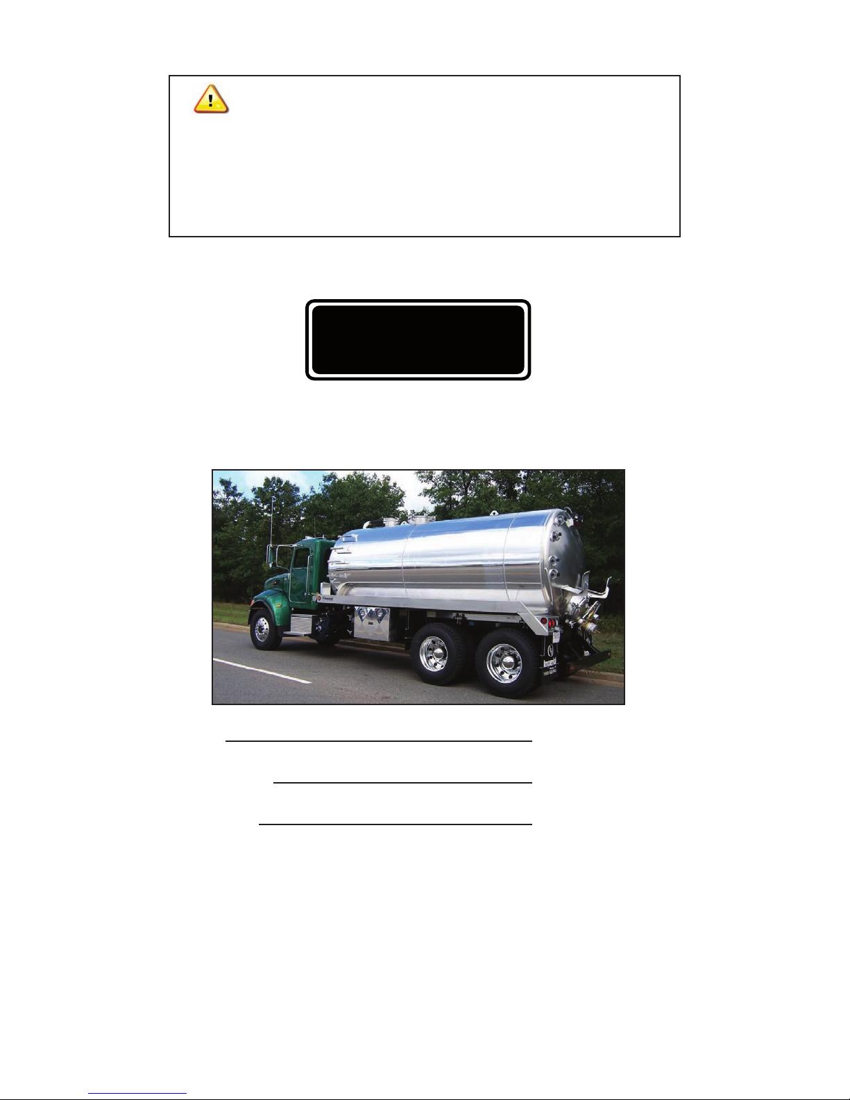
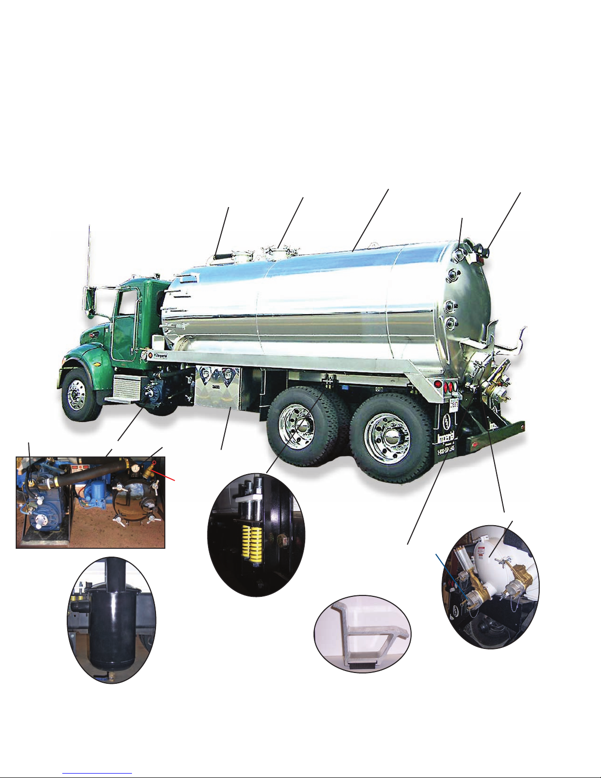
IMPERIAL TRUCK MOUNTED VACUUM TANKER MANUAL
SAFETY PRECAUTIONS
General Safety Precautions
Follow these safety precautions,and insist that those
working with you follow them.
Most industrial equipment accidents can be avoided
by observing safety precautions.Remember:a careful
operator is the best insurance against an accident.
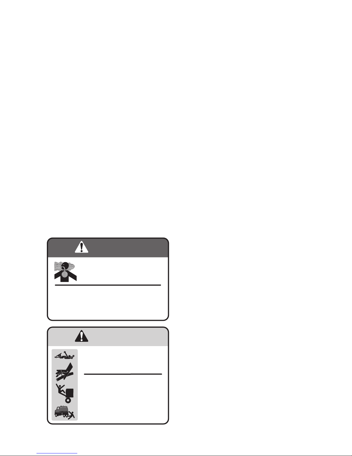
Safety Precautions for Handling Effluent
DANGER: DO NOT stand near the oil catch
muffler or discharge valve when loading or unloading
the tank. Sewer gases vented out of the oil catch
muffler will settle downward.Sewer gases can also be
expelled out of the discharge valve when releasing
tank pressure.Inhaling sewer gases can cause severe
injury or death.
WARNING:DONOTallowchildrenorirresponsible
people near your work area or equipment.Fatalities
have occurred when children have fallen or climbed
into unattended septic/holding tanks. Secure your
work area from entry of unauthorized persons in
the vicinity.
WARNING: Secure all access covers against
unauthorized entry after pumping a septic/holding
tank. Fatalities have occurred where children have
fallen into septic/holding tank openings that had not
been properly secured. Securely chain and padlock
above ground access openings. Bury underground
access openings by at least six inches of dirt.
WARNING: Always wear protective gloves, eye
protection and,appropriate clothing when working
with sewage effluent or septage. These materials
may contain hazardous chemicals, disposed of
through the drain, which can cause severe injury
or even death due to contact. These effluents also
contain bacteria,which can be a source of infection,
especially if exposed to open cuts or sores.
Safety Precautions for Entering Tanks
DANGER: DO NOT enter a transport, septic, or
holding tank without first cleaning and providing
adequate ventilation to the interior of the tank.
Sewer gas is deadly if inhaled;in addition,it depletes
the oxygen in a confined space, which can cause
asphyxiation.
DANGER: DO NOT enter a transport, septic, or
holding tank without using a respirator that supplies
grade D breathing air or a self-contained breathing
apparatus. In addition, DO NOT use this equipment
without training and familiarity with it. Entering a
tank exposed to sewage effluent without a correct
breathing apparatus, or with improper use of it, can
cause death.
DANGER: DO NOT enter a transport, septic, or
holding tank without protective clothing.Sewer gas
can be absorbed through the skin causing serious
injury or death.
WARNING:When entering a transport,septic,or
holding tank, always have someone standing by to
provide assistance,and always have a respirator that
supplies grade D breathing air or a self-contained
breathing apparatus on hand for them. In the event
of an attempted rescue,this equipment is necessary
to prevent death of the rescuer.
WARNING: Attach a safety-harness and rope to
any person that enters a transport,septic,or holding
tank.Have the safety-harness rope held by a person
standing by to provide assistance outside the tank.
An attempted rescue without the advantage of
a rope and harness can be life threatening to the
rescuer.
WARNING: Entry into a transport, septic, or
holding tank is confined space entry. Persons
entering these tanks for any purpose must be
trained in and follow OSHA confined space safety
procedures.
DANGER
DANGER