Improved Racing E5G-600 User manual

For contact information, visit www.improvedracing.com
Copyright © 2008-2019 Improved Racing Products, LLC. All rights reserved.
Rev 190528
OIL COOLER KIT FOR 2010-2011
CHEVROLET CAMARO V8
PART NUMBER: E5G-600
MADE IN USA
Important: Read these instructions in their
entirety prior to installation
2Visit www.improvedracing.com for additional support
APPLICATIONS
• Improved Racing’s E5G-600 oil cooler kit is designed for direct installa-
tion on the following vehicles:
◦2010-2011 Chevrolet Camaro V8 (SS & ZL1)
◦Z/28 Camaros may require additional parts for deleting the factory
installed heat exchangers and fans.
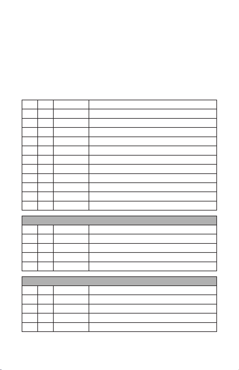
PARTS LIST & HARDWARE PACKS
Item
Qty
Part Number
Description
11 MHX-245 45-Row 3-Pass Heat Exchanger w/Hardware
21
EGM-114-TX
LSX Oil Pan Adapter for Heat Exchanger
32 OM-08-10 Adapter Fitting for Oil Pan Adapter
41 HCP-1016 1 inch ID Cushioned P-Clamp for Oil Lines
51 E5G-600-50 Line: 90° IN Adapter, 90° OUT Exchanger
61 E5G-600-51 Line: 0° OUT Adapter, 45°IN Exchanger
71 E5G-600-60 Upper Bracket & Hardware for Mounting MHX-245
81 E5G-600-61 Lower Bracket & Hardware for Mounting MHX-245
91 E5G-600-62 Rear Hose Clamp Hardware
10 1 E5G-600-64 Washer Fluid Tank Hose Tie Hardware
11 1 E5G-680
2010-2011 V8 Camaro Factory Oil Cooler Delete Kit
E5G-600-60 Hardware Pack Contents
Item
Qty
Part Number
Description
11 E5G-600-01 MHX-245 to Chassis Bracket - Top
22 HVR-1002 Rubber Isolator
32 HVR-1003 Rubber Isolator Bushing
42 HSC-1041 M8x1.25x25 Mounting Screw
E5G-600-61 Hardware Pack Contents
Item
Qty
Part Number
Description
11 E5G-600-05 MHX-245 to Chassis Bracket - Bottom
22 HVR-1002 Rubber Isolator
32 HVR-1003 Rubber Isolator Bushing
41 HSC-1054 1/4”-20 Type F Thread Cutting Screw
3
Visit www.improvedracing.com for additional support
E5G-600-62 Hardware Pack Contents
Item
Qty
Part Number
Description
11 CP-16 Billet Aluminum Hose Separator
21 HSC-1052 Grade 5 Hex Head Screw, , L = 2-3/4inch
32 HWA-1004 1/4inch Washer
E5G-600-64 Hardware Pack Contents
Item
Qty
Part Number
Description
11 HSC-1051 8.8 Class Alloy Steel M8x1.25x35 Screw
21 HWA-1005 M8 Zinc-Plated Steel Fender Washer
31 HNT-1018 M8x1.25 IFI Prevailing Torque Nut
42 HTD-1004 M8 Stud-Mount, High-Temperature Cable-Tie
E5G-680 Hardware Pack Contents
Item
Qty
Part Number
Description
11 22962571 2010-2011 V8 Camaro Upper Radiator Hose
21 12561663 LSX / Vortec Engine Block Coolant Plug
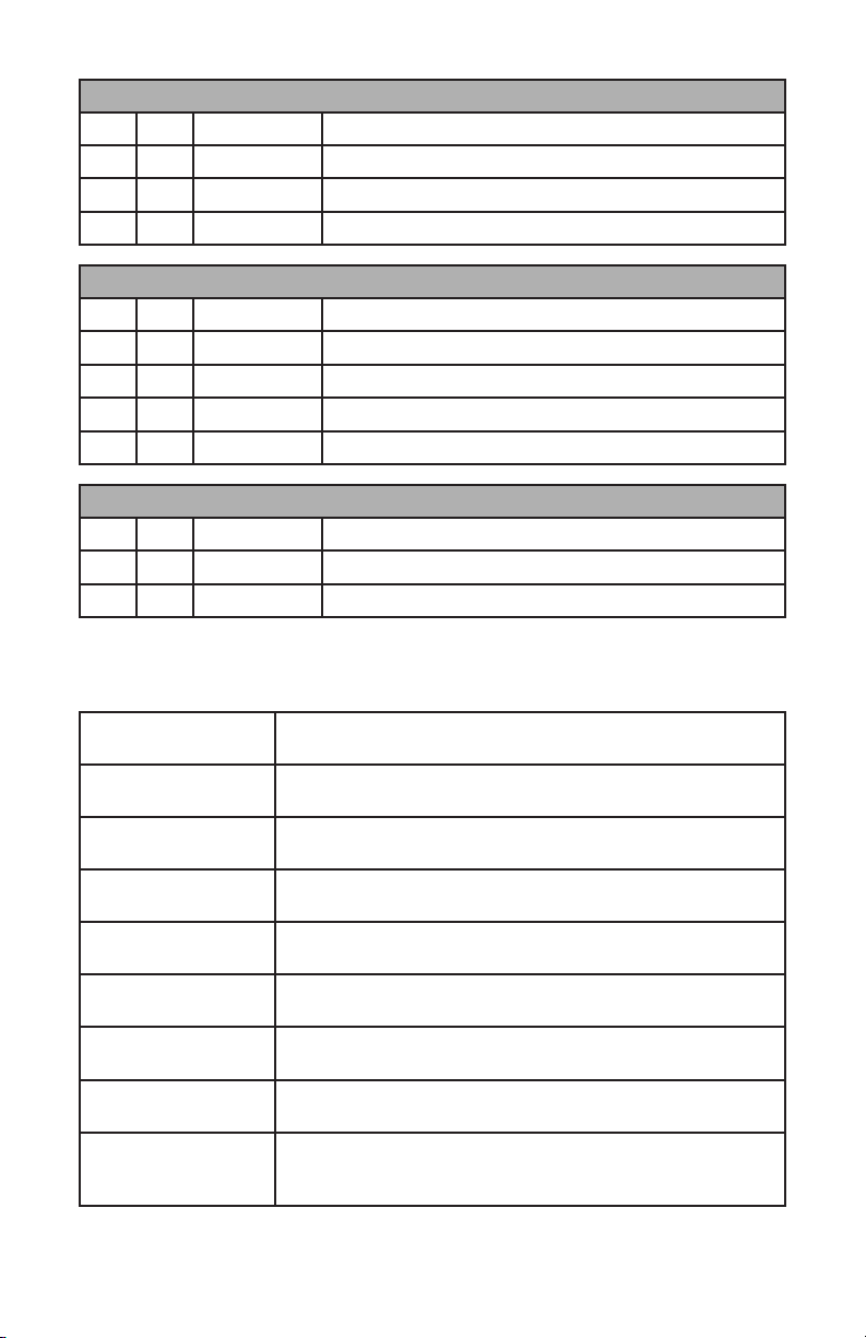
TECHNICAL SPECIFICATIONS
Maximum Operating
Temperature 302°F (150°C)
Minimum Operating
Temperature -22°F (-30°C)
Maximum Operating
Pressure 300 psi (20.68 bar)
Heat Exchanger
Material & Fabrication
45-Row Full Aluminum Tube & Fin Core with Turbulators, TIG
Welded Tanks, Billet CNC-Machined End Caps & Fittings
Adapter Fitting
Material & Fabrication
CNC-Machined 6061-T6 Aluminum, MIL-A-8625 Type II
Black-Anodize
HCP-1016 Info 1-1/2 inch (38 mm) ID P-Clamp, Zinc-Plated Steel, Black EPDM
Rubber , 210°F (99°C) Max Temp
22962571 Info Genuine GM 2010-2011 Chevrolet Camaro V8 Upper Radiator
Hose, Rubber, Black
12561663 Info Genuine GM LS / Vortec Family Engine Coolant Plug, 17 mm
Hexagon Drive, Yellow Brass, Thread-Lock Applied
E5G-600-50 Info
-10 Hose Assembly: 90° & 90° 6061-T6 Aluminum Hose-Ends,
ECO Rubber Outside Bonded to Viton Rubber Inside, Stainless
Steel Reinforced, Nylon Over-Braid, Fiberglass-Silicone Shield
4Visit www.improvedracing.com for additional support
E5G-600-51 Info
-10 Hose Assembly: 0° and 45° 6061-T6 Aluminum Hose-Ends,
ECO Rubber Outside Bonded to Viton Rubber Inside, Stainless
Steel Reinforced, Nylon Over-Braid, Fiberglass-Silicone Shield
E5G-600-60 Info
CNC-Pierced 5052-H32 Aluminum, Nitrile Rubber Vibration
Grommet, Zinc-Plated Carbon Steel Bushing, M8x1.25x16 10.9
Class Alloy Steel JIS Flange Screw
E5G-600-61 Info
CNC-Pierced 5052-H32 Aluminum, Nitrile Rubber Vibration
Grommet, Zinc-Plated Carbon Steel Bushing, M8x1.25x16 10.9
Class Alloy Steel JIS Flange Screw
WARNINGS & PRECAUTIONARY STATEMENTS
WARNING: NEVER work under a vehicle supported only by a jack.
WARNING: DO NOT CAP OFF THE OIL COOLER PORTS after the
adapter is installed. Running the engine with the ports capped will block
oil ow and result in catastrophic engine damage. If not using an oil
cooler, the IN/OUT ports must be looped together to prevent engine
damage.
WARNING: Thisproductshouldonlybeinstalledbyaqualiedme-
chanic. Improper installation could result in severe engine damage.
REMOVING THE BUMPER COVER
1.
Raise the vehicle and support with any automotive-use-approved frame
stands, lift, or ramps.
2. Open the hood of the vehicle.
3.
Apply masking tape to the fenders to prevent scratching when removing
the bumper cover.
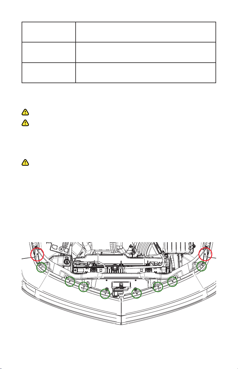
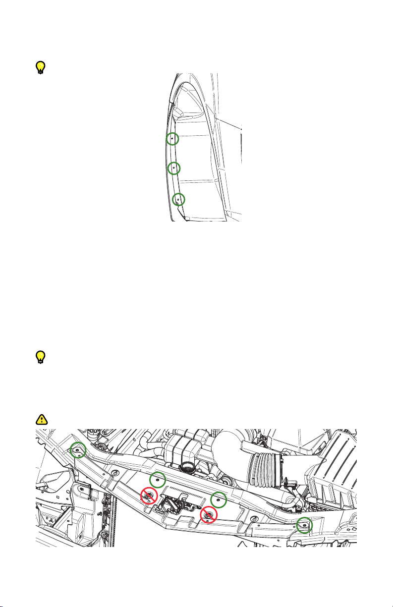
Figure 1 - Removing the Pop-Clips and Screws
5
Visit www.improvedracing.com for additional support
4.
Use a plastic prying tool to remove all of the plastic pop-clips underneath
the hood which pin the bumper cover to the radiator support, circled in
green on Figure 1.
5. Use a 10 mm tool to remove the screws at each corner under the hood,
circled in red on Figure 1.
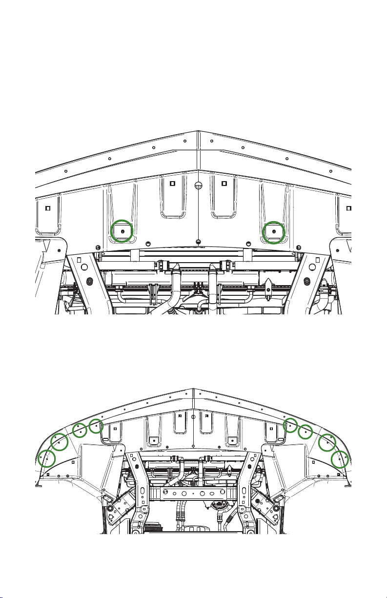
6. Underneath the car, use a 10 mm tool to remove the two screws which
hold the bumper cover to the chassis, circled in green on Figure 2.
7. Use a T20 tool to remove all screws underneath the bumper cover, im-
mediately in front of the wheels, circled in green on Figure 3. There are
four per side.
Figure 2 - Removing the Bottom Bumper Cover Screws
Figure 3 - Removing the T20 Torx Screws
6Visit www.improvedracing.com for additional support
8. Use a 7 mm tool to remove the screws in the wheel wells that attach to
the bumper cover, circled in green on Figure 4.
Tip: Take the wheels off to make this easier, or turn them side-to-side.
9. Peel-back the wheel-well linings on each side to:
a. Use a 7 mm tool to remove one screw securing the bumper cover to
the fender.
b.
Use an extended 10 mm socket wrench to remove four screws secur-
ing the bumper cover to the fender support.
c. Unplug all fog light harnesses.
10. With two people, carefully pull the bumper cover straight off the front.
Tip: Be ready to unplug the large wire harness with safety tab unlock.
11. Place the bumper cover in a safe spot until reinstallation.
12. Use a 10 mm tool to remove the four screws securing the black beak to
the front of the car, circled in green on Figure 5.
WARNING: DO NOT adjust Torx screws!
Figure 5 - Removing the Black Beak
Figure 4 - Removing the Wheel Well Cover to Bumper Cover Screws
7
Visit www.improvedracing.com for additional support
REMOVING THE FACTORY OIL COOLER
1. Placeadrainpanundertheoillterandremovethelter.
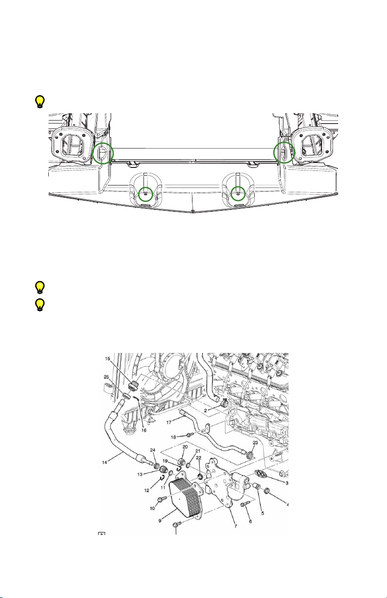
2. Remove the lower radiator shroud from the car by removing four push-
clips, circled in green on Figure 6.
Tip: Removing the bumper bar makes this easier
3. Locate the coolant lines for the factory oil cooler and pop-off the black
plastic protectors shown in Figure 7 to gain access to the clover-shaped
wireclipsthatsecurethefactorylinesintothettings.
Tip: There are two caps on the front of the factory oil cooler (#23 & #24).
Tip: There is one cap on the larger line that goes into the side of the engine
block (#25).
4. Locate the #18 screw in Figure 7 that secures the factory oil cooler tube
to the oil pan and remove the screw with a 10 mm tool.
Figure 6 - Removing the Lower Radiator Shroud
Figure 7 - Removing the Plastic Caps & Oil Pan Screw
8Visit www.improvedracing.com for additional support
5.
Removetheclover-shapedwireclipfromthelargeenginecoolanttting
usingapicortwoatscrewdrivers,circledingreen on Figure 8.
6.
Completely disconnect and set aside the spark plug wire for Cylinder #1.
7. Place another drain pan underneath the car.
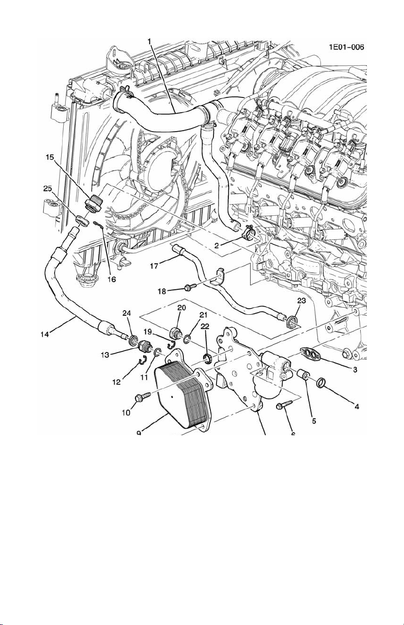
8. Use Figure 9 to:
a.
Popthe#14coolantlinefromthe#15enginetting.Allowthecoolant
todrainuntilnolongerowing.
b. Looselyplacethe#14linebackintothe#15enginetting.
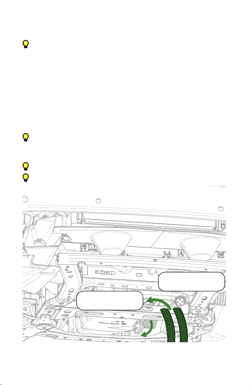
c. Locate the radiator hose circuit that feeds the factory oil cooler.
d. Locate the tee junction on the upper radiator hose.
e. Follow the small line back to the lowest hose clamp and remove the
#2 hose clamp using channel lock pliers.
f. Pull-off the hose and allow all coolant to drain completely.
g.
Completely remove the #1 upper radiator hose from the vehicle
using channel lock pliers and a plastic prying tool.
9. Replace the upper radiator hose with GM part 22962571 from the kit.
10.
Completelyremovethe#14coolantlinefromthe#15enginettingand
breakthettingloosewithabreakerbaranddeepwell34mmsocket.
11. Completelyremovetheenginetting.Wipe-upanycoolantthatspills.
Figure 8 - Removing the Clover-Like Metal Clip
Visit www.improvedracing.com for additional support 9
12.
Use a 17 mm hex bit to install the new brass coolant plug, GM part
12561663, into the engine block.
13. Torque the coolant plug to 45 lb-ft (60 N-m), followed by a 1/4turn.
14. Use a 13 mm tool to remove the four M8 screws that hold the factory oil
cooler to the side of the oil pan.
15. Remove the factory oil cooler and set aside.
16.
Use a 13 mm tool to remove the screw at the bottom of windshield washer
uidtank,circledingreen on Figure 10.
Figure 9 - Components to Remove to Replace Radiator Hose

10 Visit www.improvedracing.com for additional support
17. Use HSC-1051 and HWA-1005 from the E5G-600-64 Hardware Kit to
replace the bottom tank screw removed in the previous step.
WARNING: DO NOT over-tighten.
18. Pre-llandreinstallanewengineoillterafterlubricatingthesealwith
engine oil.
19. Reconnect the spark plug wire for Cylinder #1.
20. Reinstall the bumper bar onto the car, if needed.
Tip: Line the screws up with their paint marks inside the bumper bar to
ensurethatthebumpercoverreinstallationtstayslikenew.
Figure 10 - Replacing the Windshield Fluid Tank Screw

11
Visit www.improvedracing.com for additional support
INSTALLING THE IMPROVED RACING KIT
1.
Familiarize oneself with EGM-114 and MHX-245 by reading the in-
cluded manuals.
2. InstalltheadapterttingsintoEGM-114.Torquethettingsto20lb-ft
(27 N-m).
3. Install EGM-114 using a 5 mm hex-drive tool.
Tip:Cuta5mmkeyontheshortsidetomakealowproletoolshould
your headers interfere.
4. Use E5G-600-60 and E5G-600-61 Hardware Kits to secure the top and
bottom brackets to MHX-245, as shown in Figure 11.
5.
Use a 12 mm tool and two HSC-1041 screws from the E5G-600-60
Hardware Kit to secure the top bracket to the vehicle using the two holes
circled in green on Figure 12.
Tip:Ifthenut’sthreadsarelledwithpaint,runtheprovidedM8screws
through the hole(s) one to three times to clear the threads.
Figure 12 - Securing the MHX-245 & Brackets to the Car
Figure 11 - Brackets Attached to MHX-245
Visit www.improvedracing.com for additional support
12
6. Useananglendertomatchthe4°tiltofthefactoryradiatorstackand
hold this position to trace the hole for the lower bracket.
Tip: When on wheel ramps, re-measure the angle on your ramps.
7. Use a permanent marker to trace the hole outline for drilling.
8. Remove the cooler and bracket assembly from the car.
9. Strike the hole center with a punch and use a sharp #1 (.2280 inch) drill
bit to create the hole in the bumper bar for the bottom oil cooler bracket.
10.
Re-mountthecoolerandbracketassemblybackontothecarbyrst
securing the top bracket with a 12 mm tool and two HSC-1041 screws.
Torque the M8 screws to 24 lb-ft (33 N-m).
11.
Attach the bottom bracket to the bumper bar using a drill,
3
/
8
inch socket
and HSC-1054 thread cutting screw. DO NOT over-tighten.
Tip:Usealigned,rmpressurewithadrillsettolowspeed(Speed1).
12. Grab the oil lines and route them towards the back of the car as shown
in Figure 13.
Tip: E5G-600-50 is biased towards the passenger side of the car.
Tip: E5G-600-51 is biased towards the driver side of the car.
E5G-600-50
E5G-600-51
Figure 13 - Routing the Oil Lines Rearwards
13
Visit www.improvedracing.com for additional support
13. Applyoiltotheadaptertting’sareontheOUTportofEGM-114,and
connect the straight hose-end of E5G-600-51. Torque the hose-end to
20 lb-ft (27 N-m).
14.
Repeat Step 13 of this section with E5G-600-50 for the IN port on EGM-
114. Torque the hose-end to 20 lb-ft (27 N-m).
Tip: Connect the 90° hose-end with heat shield at the adapter side.
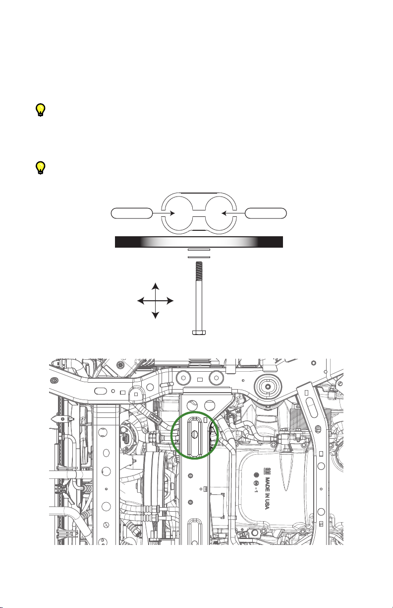
15.
Arrange HSC-1052, HWA-1003 and CP-16 from the E5G-600-62 Hard-
ware Kit as shown in Figure 14, then secure the hoses to the chassis loca-
tion circled in green on Figure 15.
Tip: Use channel-lock pliers to keep the hose clamp straight while tight-
ening the screw.
CHASSIS
REAR
FRONT
DRIVERPASSENGER
E5G-600-50 E5G-600-51
Figure 14 - E5G-600-62 Hardware Pack Arrangement
Figure 15 - Chassis Location for Rear Hose Clamp

14 Visit www.improvedracing.com for additional support
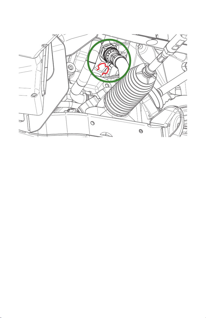
16.
Use Figure 16 to locate the power steering line that is secured to the
chassis by a cushioned clamp and use a 10 mm tool to loosen the screw
holding the clamp.
17. Expand HCP-1016 and insert the oil lines through the cushioned clamp.
18. Remove the screw from the steering line clamp on the chassis and slide
HCP-1016 over/underneath the steering line clamp, depending on what
bestsuitsthelinecongurationandpowersteeringline.
19. Reinsert the screw into the chassis and tighten to no more than 7 lb-ft
(10 N-m).
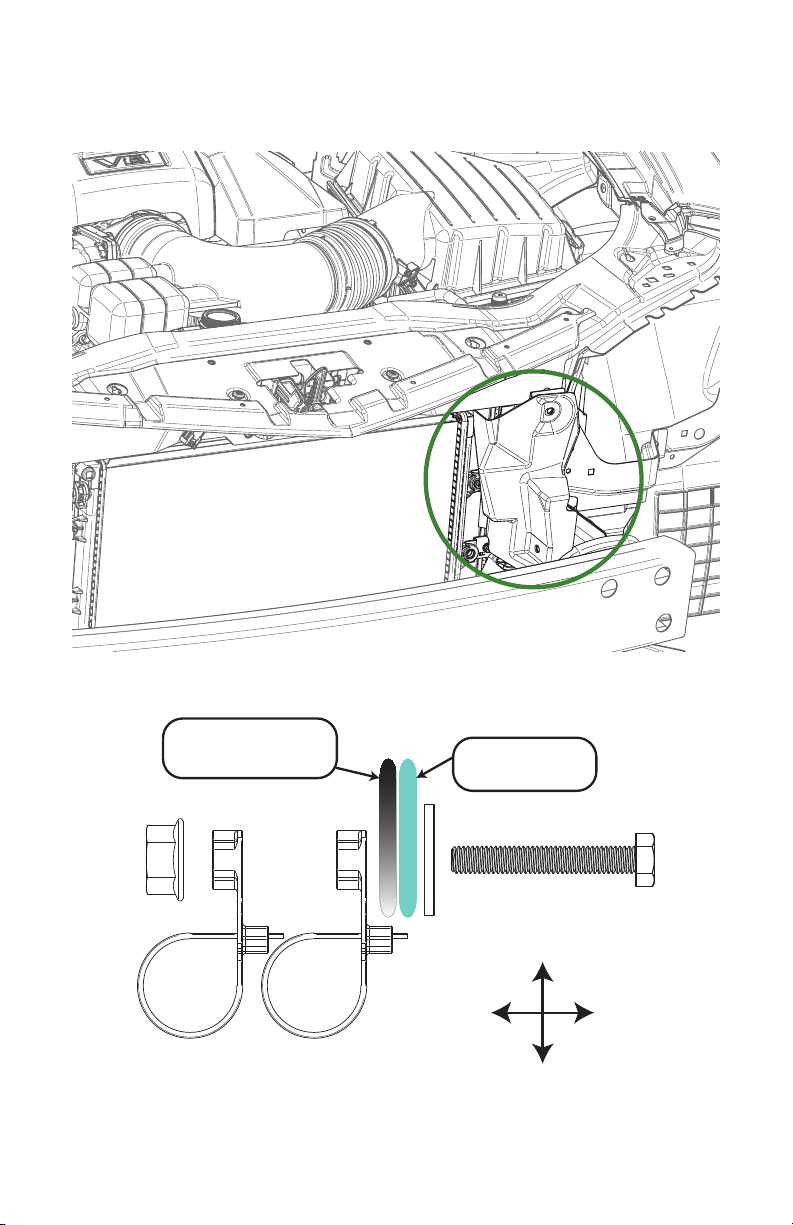
20.
Peel-back the black plastic shroud circled in green on Figure 17 and route
the system lines up towards MHX-245.
21. Use two HTD-1004 from the E5G-600-64 Hardware Kit to secure the
hosesontotheM8screwthatwasinstalledintothewasheruidtank
previously, as shown in Figure 18.
22. Applysomeoiltothelowertting’sareonMHX-245andconnectthe
45° hose-end. Tighten the hose-end to 20 lb-ft (27 N-m).
23. Pre-lltheheatexchangerwithengineoilusingatubeandfunnel.
Tip:UseaexibletubewithaMAXO.D.of0.50”(12.7mm).
Figure 16 - Chassis Location for Factory Power Steering Clamp
15
Visit www.improvedracing.com for additional support
24. Remove the tube and funnel followed by connecting the 90° hose-end
tothetopttingontheoilcooler.Tightenthehose-endto20lb-ft(27
N-m). Wipe-up any oil that spills.
WASHER
BOTTLE
FRAME &
WELDED NUT
REAR
FRONT
DRIVERPASSENGER
Figure 18 - Securing the Hoses with the High-Temperature Cable Ties & M8 Nut
Figure 17 - Black Plastic Shroud to Peel-Back & Route Hoses

16 Visit www.improvedracing.com for additional support
PREPARING FOR STARTING
1. Check the engine oil level and add oil if necessary.
2. Remove the fuel injector fuses.
Tip: Consult the vehicle’s factory service manual for the fuse locations.
3. Cranktheengineoverforvesecondstobuildoilpressure,repeating
thiscyclethreetovetimes.
4. Replace the fuel injector fuses removed previously.
5. Check the engine coolant level and add coolant if necessary.
Tip: Consult the vehicle’s factory service manual for the correct inspec-
tionandllingprocedures
6. Start the vehicle and inspect for oil and coolant leaks.
Be sure the engine does not begin to overheat.
7. Turn-off the vehicle, inspect the engine oil and coolant level and add oil
or coolant when necessary.
REINSTALLING THE BUMPER COVER
1. Use a 10 mm tool to replace the four screws securing the black beak to
the front of the car, shown in Figure 5.
2. Cut the black plastic, lower radiator shroud as shown in Figure 19.
5” MIN
Figure 19 - Trimmed Black Plastic Lower Radiator Shroud

17
Visit www.improvedracing.com for additional support
3. Reinstallthemodiedblackplasticshroudontothevehiclebynagling
the hoses into the cutout, followed by reinserting the plastic push-clips.
4. With two people, carefully place the bumper straight onto the front of
the car.
Tip: Be sure to connect all wire harnesses and lock the safety tab!
5. Peel-back the wheel-well linings on each side to:
a. Connect all fog light harnesses.
b.
Use an extended 10 mm tool to replace the four screws securing the
bumper cover to the fender support
c. Use a 7 mm tool to replace one screw securing the bumper cover to
the fender.
6.
Use a 7 mm tool to replace all screws in the wheel wells. Cite Figure 4 for
locations.
7. Put the wheels back on, if applicable.
8. Use a T20 tool to replace all screws underneath the bumper cover, im-
mediately in front of the wheels. There are four per side. Cite Figure 5
for locations.
9. Use a 10 mm tool to replace the two screws on the bottom which hold
the bumper cover to the chassis. Cite Figure 2 for locations.
10. Use a 10 mm tool to replace the screws at each corner under the hood.
Cite Figure 1 for locations.
11. Replace all of the plastic pop-clips underneath the hood which pin the
bumper cover to the radiator support. Cite Figure 1 for locations.
12. Peel-off all masking tape from the fenders.
13. Close the hood and safely lower vehicle back onto the ground.
14. Take a test drive to ensure performance is as desired.
15. Checkforloosenedttingsandleaksafter50milesofdriving.
Installation is now complete. Thank you for purchasing an Improved Racing
product!
Table of contents
Other Improved Racing Automobile Accessories manuals

Improved Racing
Improved Racing EGM-201 User manual

Improved Racing
Improved Racing FSM -RKIT Series User manual

Improved Racing
Improved Racing EFR-600-TX User manual

Improved Racing
Improved Racing EGM-301 User manual

Improved Racing
Improved Racing ENV-131-TX User manual

Improved Racing
Improved Racing EFR-605 User manual

Improved Racing
Improved Racing EGM-502 User manual

Improved Racing
Improved Racing E5G-601 User manual


