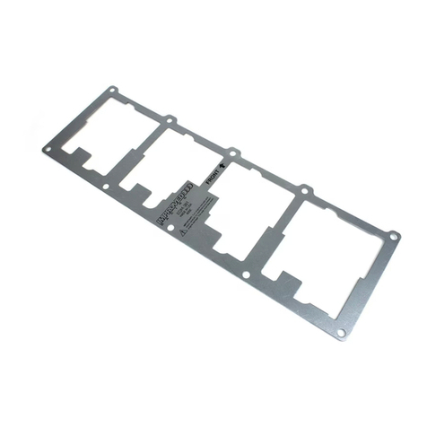
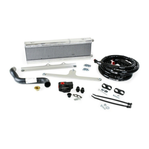
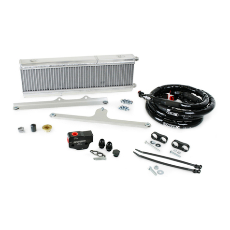
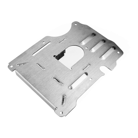
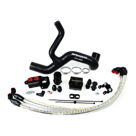
Improved Racing EFR-600-TX User manual

1996-2004 FORD MUSTANG V8 OIL
COOLER KIT
PART NO. EFR-600-TX
MADE IN USA
For contact information, visit www.improvedracing.com
Copyright © 2008-2021 Improved Racing Products, LLC. All rights reserved.
Rev 210429
Important: Read these instructions in their
entirety prior to installation.

Visit www.improvedracing.com for additional support
2
APPLICATIONS
• 1996-2004 4.6L Ford Modular V8 Mustang GT, chassis code SN95
Prior to installing this kit, Cobra and Mach 1 trims must purchase a 1.75”
to 1.50” radiator hose reducer, part number RHR-175-150.
PARTS LIST & HARDWARE
Item Qty Part Number Description
1 1 EFR-100 Remote Oil Filter and Cooler Adapter, Ford 4.6 &
5.4 Modular V8 Engine
2 1 ORB-16-28 -16 SAE ORB to 1.75” Hose Barb Adapter Fitting
3 1 EFR-800 Radiator Hose, with Clamps
4 1 MHX-520 20-Row Dual Pass Oil Cooler
5 1 EFR-600-60 Top Oil Cooler Bracket & Hardware
6 1 EFR-600-61 Lower oil cooler bracket & Hardware
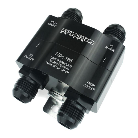
7 1 ENV-170-TX Remote Oil Filter Mount with Thermostat
(TemperatureSpecicationsinProductManual)
8 1 HSC-1039 Oil Filter Adapter Screw for ENV-170
9 8 OM-10-10 -10 SAE ORB to -10 SAE 37° Male Flare Adapter
Fitting
10 1 EFR-600-62 Oil Cooler Kit Installation Hardware
11 2 EFR-600-50 Oil Lines from EFR-100 to ENV-170
12 1 EFR-600-52 Oil Line from ENV-170 to MHX-520
13 1 EFR-600-53 Oil Line from MHX-520 to ENV-170
BEFORE YOU BEGIN
WARNING: NEVER work under a vehicle supported only by a jack.
NEVER PLUG THE FLUID PORTS ON EFR-100.
WARNING: Running the engine with plugged ports on EFR-100 will
block oil ow and result in catastrophic engine damage.
NEVER use EFR-100 without a remote oil lter plumbed.
WARNING: Running an engine without an oil lter will circulate debris
that can harm internal engine parts.
NEVER PLUG THE COOLER SIDE PORTS ON ENV-170.

Visit www.improvedracing.com for additional support 3
WARNING: Running the engine with cooler ports capped on ENV-170
will block oil ow and result in catastrophic engine damage.
Loopthelinestogethertoconnecttheuidpathsifremovingtheheat
exchanger.
WARNING: This product should only be installed by a qualied me-
chanic. Improper installation could result in severe engine damage.
WARNING: Never secure hoses to moving components.
Use zip-ties and P-clamps to ensure no hoses pinch / rub on the exhaust,
engine, suspension components and chassis.
Ensure heat exchangers are isolated from vibration.
Pre-llheatexchangerstopreventdrystartup.
Lubricateall37°aresontheadapterttingsbeforenaltightening.
Wraptaperedpipe(NPT)threadswithTeon(PTFE)tapeorapplythread
sealant to seal the threads.
LubricateO-ringsonadapterttingspriortoinstallationtoprevent
damage and ensure a leak-free seal.
Usealuminumtoolstoavoiddamagingthealuminumttings.
Properly clean all fasteners with acetone before using any thread lock.
Useisopropylalcohol(90%+)toactivatethreadlock.

Visit www.improvedracing.com for additional support
4
REMOVING THE BUMPER & FACTORY PARTS
1. Follow the instruction manual provided with EFR-100 and remove the
headlights, bumper cover and bumper bar according to the factory service
manual.
INSTALLING THE OIL COOLER ADAPTER
1. Continue following the instructions provided with EFR-100 and install
the adapter onto the engine block.
INSTALLING THE REMOTE OIL FILTER MOUNT
1. Familiarize yourself with ENV-170 by reading over the product manual.
2. Using the preexisting hole in the bumper bar, mock install the mounting
bracket and backing plate for ENV-170 using one M8 screw from the kit,
as shown in Figure 1.
Figure 1 - Remote Filter Mount Installed on Front Bumper Bar
3. Once the bracket is level, trace the hole or mark the center point.
4. Strike the hole center with a sharp punch.

Visit www.improvedracing.com for additional support 5
5. Remove all parts from the bumper bar for drilling.
6.
Drill a 3/8 inch hole into the bumper bar using a sharp, high-quality, cobalt
steel drill bit.
The bumper bar is made from hardened steel; a sharp drill bit is required
to cut through it.
7. Use a 10mm tool to secure the mounting bracket to ENV-170 with the
provided M6 screws.
8. Use a 12mm tool to install ENV-170 onto the bumper with the backing
plate using two M8 screws from the hardware kit.
9. TorquetheM8bracketscrewsto20lb-ft(27N-m).
10. Reinstall the bumper bar onto the vehicle and use the old paint marks to
get alignment correct.
11. Torque the bumper bar screws according to factory spec.
INSTALLING THE OIL COOLER & BRACKETS
1.
Remove the black plastic fascia panel in the driver side wheel well by
using a forked prying tool to remove three push-in fasteners.
Refer to Figure 4 if unsure what panel this is.
2. Use an 8mm tool to remove the power steering cooler from the radiator
support when you car is equipped with a power steering cooler.
3.
Use cable ties or string to hang the power steering cooler from the bottom
of the radiator support to reduce stress on the hoses and lines.
4.
Familiarize yourself with MHX-520 by reading over the product manual.
5.
Locate the EFR-600-60 Bracket Kit, then install the top bracket onto
MHX-520 using the supplied M8 screws and a 12 mm tool.
The ports on MHX-520 face the long arm of the bracket.
6. TorquetheM8screwsto20lb-ft(27N-m).
7. Usea1inchtooltoinstalltwoOM-10-10ttingsintoMHX-520.
8. Torquetheadapterttingsto25lb-ft(34N-m).
9. Use a 12 mm tool and the remaining screws and washers from the EFR-
600-60 Bracket Kit to loosely secure the top bracket to the radiator
support, as shown in Figure 2.
Visit www.improvedracing.com for additional support
6
Figure 2 - Remote Filter Mount Installed on Front Bumper Bar
10. Locate the EFR-600-61 Hardware Kit, then install the bottom bracket
onto MHX-520 using two M8 screws and a 12 mm tool.
11. Loosely tighten the screws to mark the bracket hole.
12.
Verify the oil cooler does not interfere with any factory components and
adjust the top bracket if it does.
13. UseananglendertoalignMHX-520parallelwiththeACcondensor/
engine radiator.
14. Once parallel, trace the outline of the bracket hole onto the bumper bar
with a permanent marker.
15. Remove the lower oil cooler bracket from MHX-520.
16. Loosen the top bracket hardware from the vehicle and carefully remove
the entire cooler and bracket assembly from the vehicle.
17.
Strike the hole-center on the bottom of the bumper bar with a sharp
punch.
18. Use a sharp, high quality 7/16inch(11mm)drillbittocutaholeintothe
bumper bar for the lower oil cooler bracket.
19.
Apply anti-seize to the included 1/4”-20 screw, then use a 7/16inch(11mm)
tool and the included jack nut wrench to install the jack nut into the 7/16
inch(11mm)hole.
Search YouTube videos for “pop jack nut installation” when unsure.

Visit www.improvedracing.com for additional support 7
20.
Remove the screw used to install the jack nut and set aside for lower
bracket installation.
21. Test-tthebottombrackettoverifyalignmentwiththenewmounting
hole, then set aside.
22. Locate the EFR-600-52 and EFR-600-53 oil lines and connect them as
follows:
a. EFR-600-52:
i. Straight = OUT TO COOLER port on ENV-170,
ii. Straight=Bottomport(IN)onMHX-520.
b. EFR-600-53:
i. Straight = IN FROM COOLER port on ENV-170,
ii. 45°=Topport(OUT)onMHX-520.
Connect the hose ends to ENV-170 after Step 23 if you did not remove
the black hood latch support bar.
Verify that hose ends to do not interfere with the hood latch support
bar after Step 23.
23. Torqueallofthettingsto25lb-ft(34N-m)EXCEPTforthettingyou
plantouseforpre-llinglater,whennotusinganenginepre-oiler.
24.
Carefully reinstall the oil cooler with top bracket and lines back onto the
car using the same top bracket hardware.
Leaveloosenedfornaladjustment.
25. Reinstall the lower oil cooler bracket onto MHX-520 using the same M8
screws as before.
26. Torquethescrewsto20lb-ft(27N-m)asdonebefore.
27. Use a 7/16inch(11mm)tooltoinstallthe1/4”-20 screw into the jack nut.
DO NOT over-tighten!
Use anti-seize to make removal less likely to spin jack nut and prohibit
fastener removal.
28. Locate the EFR-600-50 oil lines and connect each line as follows:
a. 45° Hose-End = OUT port on EFR-100
b. 150° Hose-End = IN FROM ENGINE port on ENV-170
Figure 3 shows how to orient the 150° hose-ends on ENV-170.

Visit www.improvedracing.com for additional support
8
Figure 3 - Positioning the 150°Hose Ends on ENV-170
29. TorqueallconnectionsonEFR-100andENV-170to25lb-ft(34N-m).
30. Pre-llanewoillterwithengineoilandthenlubricatetheoillterseal
before screwing it onto ENV-170.
DO NOT over-tighten!
31.
Removethehoseendthatwasleftloose,andthenpre-llMHX-520when
not using an engine pre-oiler.
32. Reconnectthehose-endtotheadaptertting.
33. Torquethettingto25lb-ft(34N-m).
34. Checkthatalloillineconnectionsaretorquedto25lb-ft(34N-m).
35. Reinstall the factory steering cooler onto the vehicle using an 8mm tool.
36. Trim the plastic fascia panel located on the front left side of the frame
rail to clear the oil lines, as shown in Figure 4.

Visit www.improvedracing.com for additional support 9
Figure 4 - Trimming the Front Left Fascia Panel
38. Use the provided zip-tie to secure the oil lines to the existing hole in the
frame rail, as shown in Figure 5.
Figure 5 - Securing the Oil Lines to the Frame Rail

Visit www.improvedracing.com for additional support
10
39. Reinstall the trimmed fascia panel, as shown in Figure 6.
Verify the oil lines clear the fascia panel and do not rub on the edge.
Figure 6 - Trimmed Fascia Panel Installed
40.
Use a
3
/
16
inch hex tool to install the hose separator from the EFR-600-62
HardwareKitinthemiddleoftheoillinesbetweentheltermountand
the engine.
Use pliers similar to Channel-Lock or Knipex pliers to hold the clamp
halves together while tightening.
Verify the hose separator allows the lines to clear any moving parts in
the engine bay before starting: Adjust if needed.
41.
Use the remaining cable tie from the EFR-600-62 Hardware Kit to retain
the lines where any rubbing might occur.
Use more cable ties if the supplied cable tie is not enough.
COMPLETING THE INSTALLATION
1. Checkthatallttingsareconnectedandtightened.
2. Check the engine oil level and add oil if necessary.
3.
Relltheengine’scoolantsystemusingthemanufacturer’sapproved
method for your Mustang.
Consultthevehicle’sfactoryservicemanualforthecorrectcoolant
specicationsandrellprocedure.

Visit www.improvedracing.com for additional support 11
4. Removethefuelpumpand/orignitionfuse(s)sothattheenginedoes
not start when turned over.
Consultthevehicle’sfactoryservicemanualforthefuse(s)location.
5. Cranktheengineoverforvesecondstobuildoilpressure,repeating
thiscyclethreetovetimes.
6. Reinstallthefuse(s).
7.
Start the engine to check for leaks or strange noises while the engine
gets up to normal operating temperature.
Verify engine oil pressure is stable and reading the correct value.
8. Turn-off the vehicle, inspect the engine oil and coolant levels and add oil
or coolant as needed.
9.
Take a drive without reinstalling the bumper cover, if possible, and verify
that no leaks or noises occur.
Leavingthenalpiecesoffallowsforeasierxes,ifrequired.
Verify test driving the car does not violate local laws regarding bumpers
and headlights before taking the test drive.
10.
Verify the car does not overheat to prove coolant levels are properly
lledagain.
11. Reinstall the front bumper, headlights and all underbody panels after a
successful test drive.
12. Inspect all parts for loosening or leaks after 100 miles of driving.
Installation is now complete. Thank you for purchasing an Improved
Racing product!
Table of contents
Other Improved Racing Automobile Accessories manuals

Improved Racing
Improved Racing FSM -RKIT Series User manual

Improved Racing
Improved Racing EGM-201 User manual

Improved Racing
Improved Racing EFR-605 User manual

Improved Racing
Improved Racing EGM-301 User manual

Improved Racing
Improved Racing ENV-131-TX User manual

Improved Racing
Improved Racing EGM-502 User manual

Improved Racing
Improved Racing E5G-600 User manual

Improved Racing
Improved Racing E5G-601 User manual