IMS 8072A User manual


165910 Dew Point Meter 8072A Manual 1 June 2014

165910 Dew Point Meter 8072A Manual 2 June 2014
Contents
Specifications ............................................................................... 3
Product Overview ........................................................................ 4
Operation .................................................................................... 6
Sample Tubing Connection ...................................................... 6
Power Connection ................................................................... 7
Dryer Performance Testing ..................................................... 7
Remote Monitoring/Datalogging ............................................ 8
Maintenance and Adjustments ................................................... 9
Monitor Disassembly and Assembly ....................................... 9
Sensor Replacement .............................................................. 10
Display Units & Alarm Set Point Adjust ................................. 10
Troubleshooting ........................................................................ 13
Dry-Down Test ....................................................................... 13
Troubleshooting Hints ........................................................... 14
Spare Parts ................................................................................. 16
Warranty

165910 Dew Point Meter 8072A Manual 3 June 2014
Specifications
DEW POINT RANGE -40qF to +15qF
(-40qC to -9qC)
TYPICAL ACCURACY ±3qF (±1.7qC)
ALARM SET POINT -10qF (-23qC)
SENSOR PART NUMBER 112254
ANALOG OUTPUT SCALING -40qF to +70qF
(-40qC to -9qC)
ANALOG OUTPUT PORT 3 pin M8 male jack
POWER REQUIREMENTS 115VAC 50/60HZ
0.15A max
(230VAC optional)
DIMENSIONS
10.75” X 9.75” x 4.75”
WEIGHT 7.0lbs

165910 Dew Point Meter 8072A Manual 4 June 2014
Product Overview
The 8072A dew point monitor is used to check the output dew
point of a desiccant dryer. The monitor has a built-in vacuum
pump which draws sample air to be measured and provides
real-time indication of dew point on an LED display. Visual and
audible alarm indicators warn when high dew points are
detected.
The dew point monitor and its accessories are housed in a
portable carrying case. Before using the monitor, familiarize
yourself with the features shown below:

165910 Dew Point Meter 8072A Manual 5 June 2014
POWER SWITCH Turns monitor ON and OFF.
ALARM SWITCH Enables local audible alarm when dew
point exceeds the alarm set point.
LINE CORD Provides connection to power.
BEEPER (not
shown)
Gives audible signal when the measured
dew point is above the alarm set point.
DEW POINT
CONDITION
INDICATORS
Green light is on when dry air is detected,
red light is on when measured dew point is
above the alarm set point.
SAMPLE TUBING Six feet of heat resistant tubing draws in
process air to be measured.
AIR FILTER Installed in-line with sample tubing,
removes fine particulates from sample air.
DESICCANT TUBE Provides dry air for testing the monitor’s
response.
TUBING STORAGE
BRACKET
Allows storage for sample tubing and
desiccant tube when not in use.
ANALOG OUT 4-20mA and 0-5V output for remote
monitoring or data logging. Mates with
standard 3 pin M8 female cable.
NOTE: The 8072A is shipped with a desiccant pack which can
be discarded when the unit is unpacked. The desiccant pack is
different than the Desiccant Tube.

165910 Dew Point Meter 8072A Manual 6 June 2014
Operation
The 8072A is designed to sample process air that is near
atmospheric pressure, NOT compressed air. If you are
attempting to monitor compressed air, consult IMS Company
for other model options.
NOTE: For best sensor life and response time, avoid sampling
ambient air of high humidity. Leave unit off when not
monitoring a dryer or hopper.
CAUTION: The carrying case is not heat resistant. It may melt
or distort if left resting on the hot parts of a heated dryer. If a
surface is too hot to touch, it is too hot for the 8072A!
Sample Tubing Connection
To enable testing of your process air, you must provide fittings
in your drying system that will accept the 8072A’s 3/16” ID
sample tubing. This can be a barbed hose fitting or a piece of
¼” copper tube that penetrates your dryer’s air hoses. This
point of attachment must be secure and leak-free. Some dryer
manufacturers provide a port for sampling. Check your dryers
owner’s manual for its location if available.
The sampling tubing supplied with the monitor can tolerate
temperatures up to 275qF (135qC). Higher process air
temperatures can be cooled to a safe level by sampling through
a few feet of ¼” copper tubing.
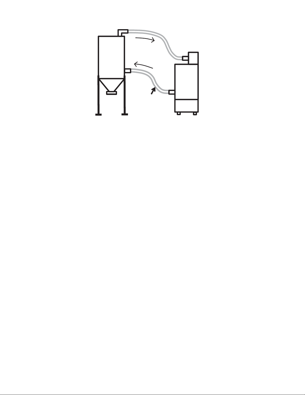
Select the sample locations based on your testing needs (refer
to diagram below). It is suggested that you have a permanently
accessible sample point. A barbed fitting with valve at the
output of the dryer is best.

165910 Dew Point Meter 8072A Manual 7 June 2014
NOTE: When storing the 8072A, carefully coil the sample
tubing and tuck it behind the tubing storage bracket. This will
prevent kinks from forming in the tubing when the lid is
closed.
Power Connection
The 8072A is supplied with a 6 foot line cord for connection to
power. Always connect the monitor to the correct supply
voltage. Do not attempt to replace the line cord with a different
plug type to accommodate other supply voltages. The 8072A
will be damaged if connected to incorrect supply voltage.
Dryer Performance Testing
The performance of a dryer can be evaluated by measuring the
dew point of its output air.
Connect the 8072A sample tubing to a point on the dryer’s
output line, before the hopper. Make sure not to exceed the
sample tubing temperature rating.
Turn on the 8072A and allow the reading to stabilize. The initial
reading will be +15qF (-9qC) until all the ambient air is purged
Dryer testing
sample location
Dryer
Hopper Air flow

165910 Dew Point Meter 8072A Manual 8 June 2014
from the monitor’s tubing and internal fittings. After a few
minutes, the reading should start to drop until a stable reading
is obtained. It can take 30 minutes or more for the unit to
stabilize when first turned on.
NOTE: Not all dryers produce a -40q
q
dew point. Check with
your dryer manufacturer for expected dew point levels.
Leave the 8072A connected and turned on during material
drying and processing. The built in red light and audible beeper
will indicate dryer trouble within moments of a dew point rise.
A constantly high reading on the 8072A may indicate a
malfunctioning dryer or one that is overloaded by damp
material in the hopper. If you suspect that the 8072A is giving
an incorrect high reading, perform the Dry-Down Test described
in the Troubleshooting section of this manual.
Remote Monitoring/Data logging
The 8072A analog output jack can be used to monitor or log
dew point over a period of time.
The output jack is a 3 pin male M8 type connector. This
connector accepts standard threaded or snap fit female M8
cables.
PIN 1 0-5V signal
PIN 3 Ground
PIN 4 4-20mA self-powered signal (current sourcing)
Note that the output scaling is -40qF to +70qF.

165910 Dew Point Meter 8072A Manual 9 June 2014
Maintenance and Adjustments
IMS Company offers a maintenance and calibration service for
the 8072A. This service should be performed annually,
especially if you are an quality certified company. During the
calibration service most common parts are checked.
Alternatively, most wearable parts can be replaced by the user
if you are not taking advantage of the calibration service.
To access the serviceable parts inside the monitor, the 8072A
panel must be removed from the carrying case.
Monitor Disassembly and Assembly
WARNING: Unplug the 8072A from power before disassembly.
Even with the power switch off, voltages are present inside the
unit.
Slide the sample tubing off of the front panel elbow.
Use a screwdriver to remove the 5 screws along the perimeter
of the panel holding it in the case. Use the sample tubing elbow
to help lift the panel straight up and out of the case.
When re-assembling the panel into the case, make sure sensor
cable wires are tucked in and not binding under the panel as
you lower it into the case.
Install the 5 mounting screws, taking care not to cross thread
the screws as you proceed. The screws only need to be snug to
the panel, do not overtighten!

165910 Dew Point Meter 8072A Manual 10 June 2014
Sensor Replacement
The internal sensor should be replaced on a yearly basis. It is
difficult to verify the accuracy of the sensor in the field. For
most users, an annual sensor
replacement can assure good
operation of the monitor. It is
recommended to replace the
sample tubing and air filter
whenever the sensor is replaced.
With the panel removed from
the case, locate the sensor
housing and pull the sensor
cable connector from the
housing. The cable will unplug
straight out.
Unscrew the hex nut from the top of the sensor housing. With
the hex nut unscrewed, remove the sensor and insert along
with gasket. The sensor
will then unplug from the
insert. Replace sensor
and inspect gasket for
damage. Reassemble all
parts, hand tighten the
hex nut, and plug in the
cable connector.
Display Units & Alarm Set Point Adjust

165910 Dew Point Meter 8072A Manual 11 June 2014
The 8072A is factory set to
display dew point in qF. The
display can be changed to
qC by jumper configuration.
With the 8072A panel
removed from the carrying
case, locate the
configurable parts near the
upper left corner of the PC
board. Move J6 and J7
jumpers to the C position to
display dew point in qC.
To change the dew point at which the monitor indicates an
alarm (high dew point indication), use the DISPLAY MODE
SWITCH labeled S1 and the ALARM ADJUST potentiometer
labeled SET1.
WARNING: The alarm set point adjustment is performed with
the 8072A powered on. Avoid touching live electrical parts
during this procedure as hazardous voltages are present!

165910 Dew Point Meter 8072A Manual 12 June 2014
OPER
SET1
SET2
S1
Apply power to the unit and turn it on with care, making sure
not to touch any electrical terminals inside.
Configure the S1 switch as shown here, with
SET1 position ON and all others OFF. In this
configuration, the front panel display will
indicate the current alarm set point. Adjust the
SET1 (Alarm Adjust) potentiometer located on
the circuit board to the desired set point.
When the front panel display indicates your
desired set point, return the S1 switches to the
normal operating configuration. The front
panel display will now show the actual
measured dew point (note that most ambient
air will cause the monitor to read +15qF).
Disconnect power and reinstall the 8072 panel into the carrying
case.
OPER
SET1
SET2
S1

165910 Dew Point Meter 8072A Manual 13 June 2014
Troubleshooting
Dry-Down Test
The desiccant tube is used to provide a reliable source of dry air
for field testing the monitor’s response. Follow this procedure
if the monitor indicates a constant high dew point but you
suspect that your process air is dry.
NOTE: The desiccant in the tube should turn blue. If the color
has faded, the desiccant should be regenerated by pouring the
desiccant into a suitable container and then heated in a 350° F
oven for one hour. This can also be done in a microwave oven
for 10 minutes set on high. Allow desiccant to cool and replace
back in tube.
Remove the yellow caps from the ends of the desiccant tube-
save them for re-
use. Connect the
sample tubing to
one end of the
desiccant tube, and
the sample air
outlet to the other
end. This will
create a closed
loop of dry air flow
through the monitor and desiccant tube. Turn on the dew point
monitor. In a few minutes, the reading should start to drop
from +15qF (-9qC). Allow up to an hour for a -40q reading. If the
monitor doesn’t respond, refer to the troubleshooting hints for
more information. Replace the desiccant tube caps when done.

165910 Dew Point Meter 8072A Manual 14 June 2014
Troubleshooting Hints
Monitor display is stuck at +15q
q
F (-9q
q
C)
Possible Cause Corrective Action
Room air getting into
monitor
Make sure the fitting at your
sample point is air tight. Also,
check for a cracked air filter and
replace if needed.
Inadequate sampling suction With monitor on, use finger to
block sample tubing. If you
don’t feel suction, the vacuum
pump may be worn or damaged,
or the 2 pin insert holding the
sensor may be cracked and
leaking. Monitor should be
serviced.
Sensor worn or
contaminated
Using a fresh desiccant tube,
perform the Dry Down test. If
response is slow, replace sensor.
Sampled air is not dry Sampled air must have a dew
point of +15qF or lower for
monitor to respond. Check the
Operation section for proper use
of the monitor.

165910 Dew Point Meter 8072A Manual 15 June 2014
Monitor reads -40q
q
when turned on and doesn’t
change
Possible Cause Corrective Action
Sensor cable disconnected Disassemble the monitor and
make sure sensor cable is
plugged into the 2 pin insert.
Sensor broken or missing Unplug the sensor cable and
short the cable pins together
with a jumper wire. Turn
monitor on and check for +15qF
on display. If so, the sensor
needs replaced.
Circuit board defective. Unplug the sensor cable and
short the cable pins together
with a jumper wire. Turn
monitor on and check for +15qF
on display. If display stays at -
40q, the monitor needs factory
service.

165910 Dew Point Meter 8072A Manual 16 June 2014
Monitor is slow to respond
Possible Cause Corrective Action
Inadequate sampling suction With monitor on, use finger to
block sample tubing. If you
don’t feel suction, the vacuum
pump may be worn or damaged,
or the 2 pin insert holding the
sensor may be cracked and
leaking. Monitor should be
serviced.
Sensor worn or
contaminated
Using a fresh desiccant tube,
perform the Dry Down test. If
response is slow, replace sensor.
Sample tubing or air filter is
dirty
Inspect sample tubing and air
filter and replace if loaded with
resin dust.
Spare Parts
Item Part No.
Sensor 112254
Air filter 103808
High temp sample tubing (per ft) 4100133
2 pin insert 0900106
Gasket for insert 1000613G
Desiccant tube 103796
Field wire-able analog out connector 0300201
Table of contents
Other IMS Measuring Instrument manuals
Popular Measuring Instrument manuals by other brands

Makita
Makita LD030P user manual

M-system
M-system R7CWTU instruction manual

Greenheck
Greenheck Sure-Aire 386719 Installation, operation and maintenance manual

Halma
Halma ALICAT SCIENTIFIC MB Series Get started

Thermo Scientific
Thermo Scientific Orion Star quick start guide

PRÜFTECHNIK
PRÜFTECHNIK VIBXPERT II Short instructions