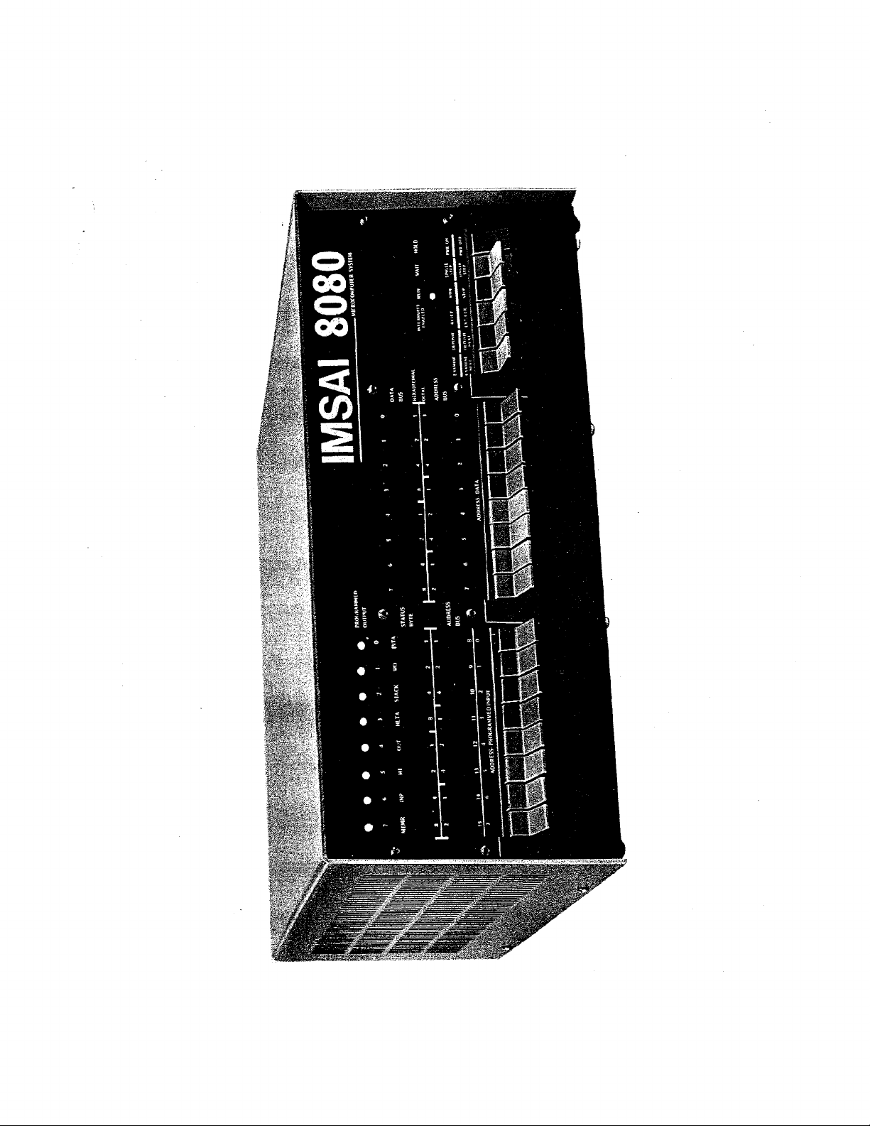
Imsai 8080 User manual

-~
ARTISAN
®
~I
TECHNOLOGY
GROUP
Your definitive source
for
quality
pre-owned
equipment.
Artisan Technology
Group
Full-service,
independent
repair
center
with
experienced
engineers
and
technicians
on staff.
We
buy
your
excess,
underutilized,
and
idle
equipment
along
with
credit
for
buybacks
and
trade-ins
.
Custom
engineering
so
your
equipment
works
exactly as
you
specify.
•
Critical
and
expedited
services
•
Leasing
/
Rentals/
Demos
• In
stock/
Ready-to-ship
•
!TAR-certified
secure
asset
solutions
Expert
team
ITrust
guarantee
I
100%
satisfaction
All
tr
ademarks,
br
a
nd
names, a
nd
br
a
nd
s a
pp
earing here
in
are
th
e property of
th
e
ir
r
es
pecti
ve
ow
ner
s.
Visit our website - Click HERE


INTRODUCTION
IMSAI
8080
System
Introduction
The
documentation
for
the
IMSAI
8080
Microcomputer
System
consists
of
several
books.
This
volume,
the
IMSAI
8080
Microcomputer
System
User
Manual,
contains
a
detailed
description
of
the
features
and
configuration
of
the
com-
puter
as
a
complete
system.
It
also
describes
the
printed
circuit
boards
that
form
the
system
building
blocks.
The
chapter
format
begins
with
a
functional
description
of
the
system
or
board,
including
brief
notes
about
all
the
fea-
tures.
The
actual
operation
of
the
system
or
board
is
then
described
in
a
theory
of
operations
section.
The
physical
and
electronic
arrangement
of
the
system
or
board
are
next
shown
with
a
photograph
and
a
schematic
•.
Assembly
of
the
board
from
a
kit
is
described
by
assembly
drawings
or
photos,
a
complete
parts
list,
and
assembly
instructions
in
each
chapter.
Finally,
the
information
that
tells
th~
user
how
to
use
the
design
features
of
the
board
to
imple-
ment
various
functional
options
is
contained
in
a
user
guide
section
for
each
board.
Operation
of
the
computer
as
a
system
is
documented
in
the
IMSAI
8080
Microcomputer
System
User
Manual
in
the
chapter
General
Assembly
and
Test
Instructions
and
also
in
the
chapter
on
the
CP-A
(Front
Panel
Control
Board).
The
software
supplied
with
the
basic
uni~,
consisting
of
a
resident
monitor,
assembler
and
text
editor
is
described
in
the
last
chapter
of
the
IMSAI
8080
Microcomputer
System
User
Manual.
This
chapter
includes
both
a
description
of
the
software
and
a
complete
object
listing.
Supporting
documentation
is
provided
by
a
copy
of
the
Intel
8080
Microcomputer
System
Users
Manual,
supplied
in
every
system
kit
to
give
IMSAI
users
the
primary
source
of
detailed
information
about
the
function
and
instruction
set
of
the
logic
implemented
by
the
intergrated
circuit
chip
set
used
in
the
IMSAI
8080.
A
handy
reference
card,
the
Intel
8080
Assembly
Language
Reference
Card,
is
suppl~ed
to
summarize
much
useful
information
from
this
manual.
To
assist
users
in
gaining
a
full
perspective
on
the
design
and
use
of
microprocessor-based
computer
systems,
IMSAI
includes
a
basic
text,
An
Introduction
to
Microcomputers.
IMSAI
is
currently
working
intensively
on
both
additional
hardware
(more
peripheral
systems,
the
Shared
Memory
Facility,
etc.)
and
system
software.
Full
documentation
of
these
addi-
tions
will
be
made
available
to
IMSAI
owners
as
it
is
produced;
the
charge
will
be
a
nominal
fee
to
cover
the
cost
of
repro-
duction.
12

System
Features
IMSAI
8080
MICROCOMPUTER
SYSTEM
FEATURES
The
IMSAI
8080
is
a
high
quality
microprocessor
based
computer
system
offering
outstanding
capability
and
flexibility
at
low
cost.
Designed
to
facilitate
simple
modular
expansion,
the
system
has
both
the
power
and
the
versatility
to
handle
a
broad
range
of
data
processing
needs.
The
IMSAI
8080
is
currently
supported
by
a
broad
range
of
peripheral
devices
and
interfaces,
and
comes
with
a
basic
resident
monitor,
assembler,
and
text
editor,
free
of
charge.
A
broad
range
of
high
level
system
software
is
now
under
development,
and
will
be
available
soon
in
both
source
and
object
form
to
registered
IMSAI
8080
owners
at
the
cost
of
reproduction
and
handling.
The
IMSAI
8080
is
available
in
kit
or
assembled
form.
While
primarily
designed
as
a
commercial
computer,
the
unit
is
configured
to
facilitate
cons~ruction
by
any
careful
assembler.
High
grade
industrial
quality
design
and
com-
ponents
are
used
in
both.kits
and
assembled
units.
Complete
documentation
is
provided
with
each
system,
including:
IMSAI
8080
Microcomputer
System
User
Manual
(this
book).
Intel
8080
Microcomputer
Systems
User's
Manual,
completely
describing
the
integrated
circuits
used,
and
the
instruction
set.
An
Introduction
to
Microcomputers,
a
fundamental
textbook
on
the
use
of
microcomputer
systems.
a
90
day
warranty
on
the
system
is
provided.
Full
factory
service
is
available
at
a
cost
commensurate
with
the
work
required.
13

IMSAI
8080
System
Functional
Description
SYSTEM
FUNCTIONAL DESCRIPTION
The
IMSAI
8080
Microcomputer
system
is
a
full-scale
general
purpose
digital
computer.
Although
small
in
size
and
low
in
cost,
the
system
is
exceedingly
versatile
and
capable
of
data
processing
in
the
complete
spectrum
of
practical
applica~
tions.
The
IMSAI
8080
used
an
8080A
microprocessor
LSI
chip
to
perform
the
cen-tral
processing
function.
The
instruction
set
provided
by
the
8080A
is
described
fully
in
Chapter
4
of
8080
Microcomputer
System
User's
Manual,
provided
as
part
of
the
IMSAI
8080
documentation
package.
The
IMSAI
8080
system
is
capable
of
unlimited
expansion,
due
to
the
bus
structure
and
IMSAI's
exclusive
shared
memory
facility,_
which
permits
parallel
processing.
The
computing
power
that
can
be
made
available
with
the
IMSAI
8080
system
building
blocks
exceeds-
that
of
any
currently
available
minicomputer.
The
operation
of
the
IMSAI
8080
is
described
in
the
manual
chapters
titled
"General
Assembly
and
Test
Instructions"
and
in
the
CP-A
Front
Panel
Control
Board
chapter.
Input/output
features
are
described
in
the
I/O
board
chapters
including
SIO
(Serial
Input/Output
board},
PIO
(Parallel
Input/Output
board)
and
UCRI
(Cassette
Recorder
Interface
board).
IMSAI
8080
SOFTWARE
FEATURES
Basic
system
software
(resident
monitor,
text
editor
and
assembler)
distributed
in
object
form,
with
listing,
and
free
of
charge.
Future
software
releases
are:
14
4K
BASIC -
upward
compatible
to
DEC
standard
SUPER-BASIC
8K BASIC -
Upward
compatible
to
DEC
standard
SUPER-BASIC
12K
BASIC -
DEC
standard
SUPER-BASIC
compatible
Floppy
Disk
Operating
System
Linkage
Editor
Macro-Assembler
with
relocatable
code
generation
12K
FORTRAN
compiler

IMSAI
8080
System
Hardware
Features
IMSAI
8080
HARDWARE
FEATURES
Flat
cable
interconnection
used
throughout.
Absolute
minimum
point-to-point
w1r1ng.
Front
panel
has
programmed
output
port
with
LED
indicators.
Front
panel
has
large
easy-to-use
paddle
handle
switches.
Front
panel
legends
are
produced
photographically
and
mounted.
behind
acrylic
panel
for
protection.
Front
panel
has
filler
to
increase
contrast
of
LED
indicators.
Long-life
LEDs
used
throughout.
Front
panel
circuit
designed
so
that
one-shot
timing
links
are
non-critical.
No
point-to-point
wiring
to
connect
or
disconnect
front
panel
to
or
from
system.
·
Attractive
custom
designed
cabinet
and
panel.
Rackmount
cabinet
available
as
special
option.
Cabinet
designed
to
facilitate
customizing
front
panel.
Sturdy
card
cage
construction.
Room
for
22
cards.
Power
supply
subchassis
with
high-current
transformer
and
computer-grade
electrolytic
capacitors.
Heavy
duty
power
supply
supplies
power
sufficient
for
a
full
complement
of
cards
{28
amps,
up
to
500
watts).
Straight-through
back
plane
wiring.
No
special
purpose
slots.
Front
panel
plugs
into
any
slot
to
operate
machine.
Double-sided
print~d
circuit
boards
with
plated-through
holes
and
solder
mask.
All
board
contact
fingers
are
gold-plated
over
nickel.
PC
board
material
is
glass-fiber-reinforced
epoxy
laminate.
On-board
power
regulation.
Power
is
regulated
by
integrated
circuit
regulators
with
thermal
current
limits.
Tantalum
board
decoupling
capacitors.
Ample
.luf
disk
ceramic
power
decoupling
capacitors.
Designed
with
latest
LSI
and
MSI
components.
Package
count
minimized.
Heavy
current
tri-state
bus
drivers
used
throughout
the
system.
System
designed
from
initial
concept
for
multi-processor,
shared
memory
options.
15

IMSAI
8080
Microcomputer
System
Specifications
MICROCOMPUTER
SYSTEM
SPECIFICATIONS
Processor:
8080A
microcomputer
chip
Directly
Accessible
Memory:
65,536
words
Word
Size:
1
byte
(8
bits)
Register
Instruction
Cycle
Time:
2
microseconds
Basic
Machine
Cycle
Time:
0.5
microseconds
Directly
Accessible
Input
and
Output
Ports:
256
Machine
Instruction
Set
Size:
78
basic
instructions
(181
instructions
with
variants)
Nested
Subroutine
Call
Capability:
Limited
only
by
memory
size
Interrupt
Capability:
8
hardware
levels
Registers:
6,
plus
stack
pointer,
program
counter
and
accumulator
Memory
Type:
Semiconductor
(1024xl
format
chips)
Cabinet:
Custom
aluminum
case
with
acrylic
front
panel
Dimensions:
19~"
x
17"
x
7"
Weight:
40
pounds
Front
Panel
Switch
Type:
Paddle
Color:
IBM
blue
and
grey
Power:
28
amp
unregulated
power
supply
with
onboard
regulators
Power
Requirement:
Under
50
watts
for
basic
system
Maximum
Power
Capability:
Up
to
500
watts
Power
Type:
115
VAC,
60
hz.
single
phase
Connections:
Mounting
space
for
10
EIA-type
25-pin
connectors
on
the
back
panel.
Opening
and
cable
clamp
provided
for
flat
cables
to
exit
from
the
cabinet.
3M
flat
cable
system
used
throughout.
16

IMSAI
8080
System
Cabinet
Assembly
Instructions
CABINET
ASSEMBLY
INSTRUCTIONS
Begin
by
installing
the
correct
number
of
plastic
card
guides
on
the
chassis
part
C's.
The
card
guides
should
be
placed
from
the
front
backwards,
an
equal
number
on
each
piece
C,
taking
care
that
the
wedge
-
shaped
opening
of
the
slot
is
positioned
upwards.
Note
that
the
two
ends
of
piece
C
arerot
symmetrical.
The
end
with
the
wider
space
between
the
last
small
hole
for
mounting
the
card
guide
and
the
end
flange
is
placed
toward
the
back
of
the
cabinet,
so
that
the
guides
will
line
up
with
the
connectors
on
the
Mother
board.
The
card
guides
should
be
assembled
starting
from
the
front
end
(with
card
guide
mounting
holes
placed
closer
to
the
end
flange).
Make
sure
you
place
the
card
guide
so
as
to
form
a
left
hand
and
a
right
hand
mounting-rail
piece.
If
this
is
not
done,
then
the
card
guides
will
be
upside
down
on
one
of
the
two
piece
'C's
when
they
are
mounted
into
the
cabinet.
The
card
guides
are
most
easily
mounted
using
a
small
press
and
placing
the
tab
of
each
card
guide
in
position
started
into
the
hole
and
pressing
them
into
place
un-
til
the
mounting
tabs
snap
through.
A
drill
press
with
a
large
flat
-
headed
screw
mounted
in
the
chuck
works
well
with
this
op-
eration.
(Alternately,
the
card
guides
may
be
installed
very
care-
fully
using
needle
nosed
pliers).
care
should
be
taken
that
the
tabs
are
started
into
the
hole
when
beginning
to
press
the
guide
into
place,
otherwise
one
or
both
may
be
bent
out
flat
and
bro~en
off.
One
end
of
the
guide
at
a
time
should
be
inserted
rather
than
trying
to
press
both
ends
in
simultaneously.
If
a
fan
is
to
be
installed
in
the
chassis,
it
should
be
assembled
on
the
back
frame
piece
Al
at
this
time
using
the
hardware
in
the
fan
kit.
The
fan
terminals
should
be
towards
the
top
and
towards
the
Mother
board
side
of
the
chassis.
Next,
the
power
cord
should
be
inserted
using
the
special
gronunet
in
the
hole
provided
on
the
back
panel.
4
to
6
inches
of
the
power
cord
should
be
left
on
the
inside
of
the
cabinet.
If
the
power
cord
grommet
is
squeezed
together
with
a
pair
of
pliers
before
in-
sertion
into
the
cabinet
back,
it
will
ease
the
job
of
inserting
this
tight
fitting
grommet.
To
insert
the
grommet,
the
power
cord
should
be
pulled
through
the
hole
nearly
to
the
point
where
the
grommet
has
been
placed
around
the
power
cord,
then
the
outer
edge
of
the
grommet
can
be
grasped
with
a
pair
of
pliers
and
squeezed
slightly
and
inserted
in
the
hole
and
worked
in
while
slight
tension
is
also
being
put
on
the
cord
from
the
back
side
to
assist.
Work-
ing
this
grommet
in
by
rocking
it
back
and
forth
works
better
than
just
pushing
harder.
The
front
and
back
frames
can
now
be
screwed
to
the
base
plate
using
6-32x5/l6"
machine
screws.
Note
that
the
back
frame
fits
under
the
base
plate
and
the
front
frame
fits
on
top
of
the
base
plate,
set
back
about
l"
from
the
front
edge
of
the
base
plate.
Next,
install
1 - 1

IMSAI
8080
System
Cabinet
Assembly
Instructions
the
two
card
frames
between
the
front
and
back
frames.
Use
two
6-32x5/l6"
machine
screws
at
each
end
of
each
card
frame.
The
front
and
back
frames
have
slotted
holes
allowing
the
card
frames
to
be
adjusted
slightly
when
the
Mother
board
is
installed
on
the
base
plate
and
boards
are
inserted
in
the
card
frames.
The
self-adhesive
rubber
feet
can
then
be
separated
from
each
other,
the
protective
backing
removed,
and
placed
on
the
bottom
of
the
cabinet
spaced
3
inches
along
the
left
hand
and
right
hand
edge
of
the
bottom,
to
support
the
cabinet
weight.
BASE PLATE
HOLE
IDENTIFICATION
The
base
plate
currently
being
shipped
is
a
universal
base
plate,
with
extra
holes
for
accomodating
two
styles
of
mother
board
mount-
ing
systems
and
two
styles
of
power
supplies.
For
the
power
supply
and
mother
board
systems
shipped
with
your
kit:
1.
Place
the
Power
Supply
p.c.
board
in
the
base
plate
cavity
and
line
up
the
holes
in
the
p.c.
board
with
the
correspon-
ding
holes
in
the
base
plate
and
mark
(e.g.,
with
a
felt-
tip
pen)
which
holes
are
to
be
used.
2.
The
mother
board
mounting
system
use's
the
two
rows
of
12
holes
each
on
the
left
side
of
the
base
plate.
SWITCH
ESCUTCHEON
INSTALLATION
When
the
CP-A
Front
Panel
Assembly
has
been
mounted,
the
Switch
Escutcheon
{piece
A2B)
can
be
installed
on
the
.base
plate
at
the
front
of
the
computer
using
four
6-32x5/16"
Phillips
pan
head
machine
screws.
Note
that
the
Escutcheon
should
fit
under
the
base
plate.
CABLE
CLAMP
INSTALLATION
Cables
that
do
not
fit
the
connector
holes
on
the
back
frame
of
the
chassis
may
be
clamped
for
strain
relief
at
the
top
of
the
back
frame
using
the
L -
shaped
aluminum
bar,
piece
K.
Install
using
two
6-32x~"
Phillips
pan
head
machine
screws.
Depending
on
the
thickness
of
the
cables
being
clamped,
either
of
the
two
sides
of
the
angle
may
be
used.
TABLE TOP
COVER
INSTALLATION ·
To
install
the
table
top
c·over,
slide
the
cover
carefully
over
the
chassis
frame
and
hold
in
place
with
four
6-32x~"
Phillips
pan
head
machine
screws.
Refer
to
Appendices
for
an
exploded
view
of
·the
chassis
cabinet.
1 - 2

IMSAI
8080
System
Cabinet
Assembly
Instructions
RACK
MOUNT
SYSTEM
ASSEMBLY
INSTRUCTIONS
For
the
rack
mount
system,
begin
by
installing
the
rack
mount
cover
on
the
chassis.
Use
five
6-32x5/16"
Phillips
pan
head
machine
screws.
Next
install
the
left
and
right
side
plates
to
the
chassis
with
the
front
flanges
pointing
outwards.
Use
four
6-32x~"
Phillips
pan
head
machine
screws
on
each
side
plate.
The
forward
holes
in
each
pattern
on
the
side
plates
should
be
used.
Next
mount
the
assembly
in
the
rack
using
two
screws
on
each
side
of
the
front
flanges.
Hardware
requirements
for
mounting
the
assem-
bly
into
the
rack
will
vary
according
to
the
individual
rack.
It
is
suggested
that
the
rear
of
the
assembly
also
be
supported
in
the
rack.
Finally,
mount
the
front
face
panel
onto
the
side
plate
flanges
using
four
#10
round
head
screws
and
clips.
NOTE:
for
installations
without
slides
where
easy
removal
of
the
computer
~s
desired,
the
side
plates
can
be
mounted
directly
in
the
rack
and
the
computer
can
be
slid
on
its
rubber
feet
en
the
bottom
flanges
of
the
side
plates.
The
rear
of
the
side
plates
in
this
case
should
be
fastened
securely
to
t~e
back
of
the
rack
cabinet.
1 - 3

ITEM
.
Screw
Screw
Screw
Screw
Nut
8080
Rack
Mount
Parts
List
IMSAI
PART i QUANTITY DESCRIPTION
93-3010008
93-3070001
93-3070002
93-3010012
20-3302001
20-3502001
20-5707001
20-5708001
21-5650001
1
1
1
1
5
8
4
4
8
Rack
Mount
Front
Panel
Rev.
C
Rack
Mount
Left
Slide
Rev.
C
Rack
Mount
Right
Slide
Rev.
0
Rack
Mount
Cover
Rev.
B
6-32x5/16"_Phillips
Pan
Head
Machine
Screw
6-32x~n
Phillips
Pan
Head
Machine
Screw
il0x3/4n
Flat
Head
Type
B
Self-Tapping
Sheet
Metal
Screw
il0x3/4"
Button
Head
Type
B
S~lf-Tapping
Sheet
Metal
Screw
.
Speed
Nut,
Tinnerman
c
9031-loz.-1
1 - 7

IMSAI
8080
Chassis
Parts
Li.st
ITEM
PART
i QUANTITY DESCRIPTION/IDENTIFYING
MARKS
Back
Frame
93-3010003
1
Back
Frame
"Al"·
Front
Piece
93-30~0010
1
Painted
Front
Piece
"A2B"
cabinet
Base
93-4010004
l
cabinet
Base
"A3"
Front
Frame
93-30~0001
1
Front
Frame
"B"
Card
Frame
93-3010002
2
Card
Frames
"C"
cable
Clamp
93-3010013
1
Cable
Clamp
"X"
"DANGER"
Label
l
"DANGER"
Labe~
on
right
card
frame
Rubber
Feet
28-0400001
6
Adhesive
backed
rubber
feet
Screw
2Q-3302001
25
6-32x5/l6"
Phillips
pan
head
machine
screws
Screw
2Q-350200l
2
6-32x~"
PhiJ.lips
pan
head
machine
screws
capacitor
91-0300001
Brace
2
capacitor
Braces
with
foam
backing
Cover
93-4010005 1
Table
Top
Cabinet
Top
Screws
20-3502001
4
6-32~"
Phillips
Pan
Head
Mac.l:une
1 - 8

INTRODUCTION
This
chapter
contains
the
following
sections:
1.
Kit
Unpacking
Instructions
IMSAI
8080
System
General
Assembly
and
Test
Instructions
2.
Construction
Hints
-
general
notes
on
how
to
build
your
kit.
3.
Recommended
Overall
Order
of
Assembly
(includes
cross-reference
to
chapters
where
specific
assembly
instructions
for
the
various
subrnodules
will
be
found).
4.
Mainframe
Assembly
-
assembly
instructions
for
integrating
Chassis
with
Power
Supply,
Mother
board
and
Front
Panel,
and
instructions
for
testing
the
Power
Supply.
5.
System
Functional
Test
-how
to
check
out
your
overall
system.
17

18
KIT
UNPACKING
INSTRUCTIONS
IMSAI
8080
System
General
Assembly
and.
Test
Instructions
1.
Remove
all
packages
from
the
outer
box.
For
a
standard
IMSAI
8080
kit,
these
will
consist
of:
a.
Documentation
Set
(Manual
plus
two
books)
b.
Cabinet
Base
Plate
c.
Table
Top
Cover
(or
Rackmount
cover
and
Rackmount
painted
pieces)
d.
Two
large
inner
boxes
e.
Two
small
inner
boxes.
2.
Largest
inner
box
contains
flat
parts
such
as
pc
boards,
small
sheet
metal
parts,
two
plastic
panels
and
a
mailing
tube
containing
the
front
panel
mask
and
paper
backing·
sheet
(latter
is
deleted
if
an
OEM
machine
has
been
ordered).
3.
The
next
smaller
size
inner
box
contains
plastic
sacks
of
components.
(There
will
be
a
plastic
sack
with
a
parts
list
corresponding
to
each
pc
board,
plus
sacks
for
the
chassis
and
rackmount
hardware
and
a
sack
containing
the
paper
tape
for
the
IMSAI
Self-Contained
System
software.
4.
One
of
the
two
small
boxes
contai~s
the
large
components
for
the
Power
Supply
(transformer,
capacitors,
etc.).
5.
The
second
small
box
is
either
empty·(serving
as
a
spacer
box
for
packaging
purposes)
or
contains
overflow
from
the
sack
parts
box.
6.
Unpack
plastic
sacks
only
when
you
are
ready
to
begin
assembly
of
that
particular
module.
If
any
parts
are
missing,
contact
IMSAI
Customer
Service
for
immediate
replacement.
7.
Be
careful
in
handling
the
painted
sheet
metal
parts,
the
plastic
parts
and
the
film
negative
to
avoid
scratching.
PC
boards
should
not
be
stacked
without
protective
material
between
to
avoid
destroying
or
shorting
traces.

CONSTRUCTION HINTS
GENERAL
IMSAI
8080
System
General
Assembly
Notes
The
IMSAI
8080
microcomputer
is
a
complex
piece
of
electronic
equipment.
This
section
covers
a
number
of
items,
each
of
which
must
be
followed
to
insure
a
working
system
at
the
completion
of
assembly.
This
entire
section
must
be
read
completely
before
beginning
assembly,
and
the
builder
must
refer
back
to
the
notes
in
this
section
often
enough
to
in-
sure
that
no
components
are
installed
incorrectly.
While
each
assembly
step
is
easy
to
do
correctly,
there
are
many
steps
and
it
is
also
easy
to
do
one
or
more
incorrectly,
and
much
more
time
will
be
spent
solving
a
problem
than
would
have
been
needed
to
prevent
it.
There
may
be
items
about
which
you
are
not
completely
sure
during
assembly.
Should
this
occur,
DO
NOT
CONTINUE.
Study
the
manual
to
see
if
you
can
resolve
your
question,
or
seek
the
help
of
someone
more
knowledgeable
in
digital
electronics.
If
you
feel
your
questibn
is
not
resolved
by
further
study
or
asking
whoever
is
available
to
you,
call
IMSAI.
This
will
enable
you
to
do
a
better
construction
job,
and
it
will
enable
us
to
revise
the
manual
so
that
it
will
be
of
more
assistance
to
you.
We
recognize
that
some
builders
will
have
had
very
little
experience
in
assembling
electronic
kits,
and
it
is
our
intention
to
continually
revise
the
manual
based
on
comments
by
users,
so
that
even
the
most
inexperienced
build-
er
can
achieve
the
best
unit
available
with
a
minimum
of
effort.
No
question
is
too
simple
to
call
about
if
you're
not
sure
about
it.
TOOLS
AND
WORKPLACE
It.is
next
to
impossible
for
even
an
experienced
builder
to
produce
a
good
machine
unless
proper
tools
and
an
adequate
workspace
are
available.
Thekit
does
not
require
much
space
to
work
in,
but
enough
table
surface
should
be
available
for
the
piece
being
worked
on,
all
the
tools
needed
for
that
piece,
and
an
orderly
arrangement
of
the
components
which
wil.l
be
used
in
assembling
that
piece.
The
work
area
should
be
very
well-lit,
with
no
shadows.
If
the
entire
room
is
not
well-lit
by
ceiling
or
window
light,
then
at
least
two
bright
lamps
should
be
used,
preferably
one
on
either
side
and
slightly
behind
the
chair
to
help
eliminate
shadows.
You
may
want
to
protect
the
table
surface
with
cardboard
or
newspaper.
19

20
IMSAI
8080
System
General
Assembly
Notes
The
most
important
single
item
in
assembly
is
the
solder-
ing
iron.
It
is
critical
enough
that
a
separate
part
of
this
section
is
devoted
to
it.
Other
tools
which
are
ab-
solutely
necessary
to
do
an
adequate
assembly
job
are
screw-
drivers
to
fit
the
screws
used
in
the
kit
(both
straight
slot
and
phillips),
a
small
pair
of
diagonal
cutters
(pre-
ferably
a
4"
pair,
flush-cutting),
small
needle-nosed
pliers,
and
a
wire
stripper.
A
1/4"
nut
driverwi.ll
make
cabinet
assembly
very
much
easier,
as
the
sheet-metal
screws
used
are
designed
primarily
to
use
a
nut-driver.
A
voltmeter
should
be
available·for
testing.
Any
inexpensive
meter
(VOM)
with
DC
voltage
scales
between
5
and
30
volts
should
do.
Do
not
attempt
to
assemble
the
kit
until
you
have
the
tools
necessary;
damaged
parts
cannot
be
replaced
under
warranty.
SOLDERING
Almost
every
problem
with
an
assembled
kit,is
a
soldering
problem.
If
you
have
never
soldered
before,
or
_if,
you
have
done,some
soldering
but
do
not
yet
have
facility
in
making
good
soldering
joints
both
quickly
and
every
time,
practice
before
beginning
assembly
on
the
IMSAI
8080
boards.
Obtain
some
extra
#20
hook-up
wire
and
solder
locally
and
solder
pieces
together
until
you
feel
comfortably
able
to
quickly
make
a
good
joint.
The
importance
of
good
solder
joints
is
just
too
great
to
convey·
adequately
here;
but
don't
be
scared
off,
because
once
you
get
the
hang
of
it,
they're
very
easy
to
do.
Soldering
Irons
There
are
a
great
many
tools
available
with
the
name
"solder-
ing
iron".
Two
thirds
of
these
are
not
appropriate
to
small
electronics
assembly
and
if
used
are
almost
certain
to
damage
both
parts
and
boards.
The
problem
with
most
of
these
are
that
they
are
too
big
and
too
hot.
Note
that
most
every
soldering
"gun"
is
in
the
too
big,
too
hot
class.
Proper·
soldering
irons
are
easily
available
at
any
local
hobbyist
electronics
outlet,
and
they
are
not
expensive.
Use
a
30-40
watt
iron
with
a
small
tip,
such
as
an
Ungar
776
with
a
7155
tip.
If
you
wish
to
invest
in
a
top-quality
tool,
a
temper-
ature-controlled
tip
model
such
as
the
Weller
W-TCP
with
a
small
700°F
tip
is
well
worth
the
extra
cost.
Many
irons
are
available
with
either
unplated
copper
tips
or
plated
tips.
Though
slightly
more
expensive,
the
plated
tips
last
very
much
longer
and
give
superior
service.

Solder
IMSAI
8080
System
General
Assembly
Notes
Using
the
proper
solder
is
as
important
as
using
the
proper
iron,
and
there
are
many
solders
to
choose
among.
In
normal
electronics
assembly,
separate
paste
or
liquid
flux
is
not
used.
Rather,
.a
solder
with
a
"core"
of
rosin
(or
resin)
base
flux
is
used.
This
flux
(contained
in
the
hollow
center
of
the
solder)
should
be
sufficient.
Absolutely
avoid
any
solders
using
an
acid
flux.
(Or
any
cans
of
acid
flux
-
unless
a
can
of
flux
says"rosin"
you
may
safely
assume
it
is
an
acid
flux.
Acid
fluxes
are
used
for
mechanical
sold-
ering
where
the
surfaces
are
not
as
clean
as
those
in
elec-
tronic
assembly.
They
are
corrosive
and
will
typically
damage
a
printed
circuit.
Also
very
important
is
the
rat~o
of
tin
to
lead
used
in
the
solder.
Best
to
use
is
63%
tin,
37%
lead,
called
63/37
or
eutectic.
Much
more
common
is
60/40,
which
is
still
a
very
good
solder.
Avoid
using
50/50
or
40/60,
even
though
they're
a
little
cheaper.
The
higher-lead
ratios
solidify
gradually,
while
the
63/37
solidifies
almost
instantaneously,
making
"cold
solder
joints"
very
much
less
likely.
Also
important
is
the
gauge
(or
diameter)
of
the
solder.
For
fine
electronics
work
a
fine
gauge
should
be
used,
such
as
#20
(from
#19
to
#22
is
OK).
Again,
the
correct
solder
is
easy
to
obtain
from
any
local
hobbyist
electronics
outlet
or
TV
repair
shop.
ERSIN
Multicore
or
KESTER
are
two
brands
you
can
count
on
for
good
results.
The
solder
in-
cluded
in
the
kit
should
be
sufficient.
If
for
some
reason
it
is
not,
and
you
cannot
obtain
the
proper
solder
locally,
DO
NOT
USE
any
substitutes.
More
solder
of
the
proper
type
can
be
<btained
from
IMSAI •
Soldering
Technique
For
a
joint
to
solder
correctly,
enough
heat
must
be
applied
so
that
both
pieces
of
metal
get
hot
enough
to
melt
the
solder.
The
tip
of
the
iron
should
be
applied
so
.that
it
touches
both
the
wire
and
the
foil
pad
on
the
board.
The
end
of
the
solder
should
then
be
touched
to
the
junction
of
the
iron,
lead,
and
pad,
so
that
a
small
amount
melts
and
"wets"
the
joint
(flows
smoothly
on.
both
the
lead
and
pad).
As
soon
as
the
joint
has
wet,
the
iron
can
be
removed,
and
the
joint
inspected
immediately.
Careful
inspection
of
each
joint
is
the
key
to
successful
soldering.
While
the
solder
is
being
applied,
watch
the
joint
carefully.
You
should
be
able
to
21

22
IMSAI
8080
System
General
A~sembly
Notes
see
the
solder
flow
onto
the
two
surfaces.
It
should
flow
around
the
lead,
and
if
you
see
that
the
solder
has
flowed
only
on
one
side
of
the
lead,
the
iron
should
be
re-applied
(while
watching
the
joint)
to
heat
the
joint
enough
for
the
solder
to
flow.
(The
typical
reason
for
solder
to
flow
only
half-way
around
a
lead
is
that
not
enough
heat
was
applied.)
For
the
normal
joint;
only
a
small
amount
of
solder
is
needed
(approximately
1/8"
of
20
gauge
solder
wire)
for
it
to
flow
all
the
way
arqund
the
lead.
Also,
for
the
normal
joint,
only
2
to
4
seconds
of
heat
applied
from
the
iron
is
necessary.
More
heat
and
solder
will
be
.needed
for
some
joints
with
larger
leads
and
holes
or
large
foil
areas,
but
if
more
heat
or
solder
is
needed
on
typical
component
leads
(like
IC's),
it
is
an
indication
that
some-
thing
is
not
right.
Since
nearly
all
the
holes
in
IMSAI
printed
circuit
boards
are
plated-through
(the
inside'
walls
of
the
hole
have
a
metal
surface,
connecting
the
pads
on
the
opposite
sides
and
providing
greater
area
for
solder
to
adhere
to)
some
solder
will
typically
wick
through
and
be
visible
on
the
top
side
of
the
board.
This
is
normal.
If
small
drops
of
solder
appear
on
the
top
side,
it
is
an
indication
that
too
much
solder
is
being
applied,
along
with
more
than
suf-
ficient
heat.
These
balls
of
solder
can
easily
short
to
neighboring
pins
and
must
be
avoided.
If
the
correct
amount
of
heat
or
less
than
the
correct
amount
was
used
along
with
too
much
solder,
the
solder
remains
on
the
bottom
of
the
board
(the
side
the
solder
is
_always
applied
from)
and
forms
a
blob
which
can
easily
short
to
neighboring
pads
or
traces.
If
one
of
the
small
gaps
between
fo~l
pads
or
traces
has
been
shorted
with
too
much
solder,
it
can
often
be
un-
shorted
by
running
the
hot
iron
lightly
down
the
shorte~
trace,
re-melting
the
solder
at
the
shorted
point
and
pulling
it
away
with
the
iron.
Do
not
leave
iron
on
traces
or
pads
too
long
when
soldering
or
fixing
a
short,
as
overheated
traces
easily
come
off
the
board.
As a
result,
very
special
care
must
be
exercised
for
any
component
removal
operation.
The
tip
of
the
iron
must
be
kept
clean
to
work
well.
Most
stores
that
carry
irons
also
carry
small
sponges
in
holders
designed
for
cleaning
hot
~ips.
The
tip
is
simply
wiped
on
the
wet
sponge
quickly.
A
damp
rag
will
serve
as
well
though
less
convenient.
The
tip
must
be
kept
adequately
tinned
at
all
times
to
avoid
an
oxide
coating
forming.
It
should
appear
bright
and
shiny.
A
small
amount
of
solder
should
be
melted
onto
the
tip
each
time
it
is
cleaned
unless

IMSAI
8080
System
General
Assembly
Notes
a
joint
is
to
be
made
immediately.
If
a
tip
becomes
oxidized,
dipping
it
in
a
can
of
rosin
flux
is
usually
sufficient
to
enable
solder
to
flow
on
it
again.
They
may
be
cleaned
of
oxide
by
fine
steel
wool
or
other
abrasive,
but
a
plated
tip
should
never
be
filed.
The
tip
of
the
iron
should
never
have
enough
solder
on
it
that
it
could
drip
off.
If
you
find
that
solder
tends
to
drip
off
the
tip,
you
are
undoubtedly
using
too
much
solder.
A
solder
drip
on
a
P.C.
board
is
often
extremely
difficult
to
see,
since
it
is
the
same
color
as
the
traces,
and
it
is
sure
to
short
several
traces
and
cause
trouble
or
damage
components
when
the
board
is
operated.
Inspect
your
boards
very
carefully
for
any
such
solder
drips,
shorts
near
soldered
leads,
incompletely
soldered
leads,
and
unsoldered
leads.
A
100%
inspection
of
soldering
should
catch
99%
of
all
problems
before
the
board
is
even
turned
on.
When
soldering
components
with
long
leads
(resistors,
etc)
we
suggest
clipping
the
leads
after
soldering
so
that
lead
clipping
gives
you
an
easy
and
positive
way
to
check
all
the
joints
on
those
components.
A
completed
unit
will
typically
run
when
first
turned
on
if
the
soldering
was
done
correctly.
MOS
IC.HANDLING
Some
of
the
chips
in
the
kit
are
MOS
type
chips
(such
as
the
8080A,
8111
and
8251).
MOS
chips
are
sensitive
to
static
electricity
and
other
large
transient
voltages.
In
order
to
prevent
damaging
these,
some
precautions
should
be
followed.
They
all
relate
to
avoiding
the
discharge
of
static
through
the
pins
on·one
of
these
chips.
Avoid
working
in
a
room
with
very
low
humidity.
Wearing
cotton
fabric
or
other
non-static
forming
fabrics
will
help.
Air
directly
from
a
heater
vent
is
typically
ex-
tremely
low
in
humidity
and
should
be
avoided
in
the
work
area.
Keeping
everything
involved
(chip,
board,
iron,
tools,
boxes,
chip
containers,
work
surfaces
and
you)
at.the
same
potential
is
required,_and
the
biggest
step
in
achieving
this
is
continuous
physical
contact
between
them.
For
example,
before
removing
a
chip
from
a
box
and
setting
it
on
the
table,
the
box
should
be
set
on
the
table,
you
should
touch
the
table,
and
only
then
pick
up
the
chip
to
place
it
on
the
table.
Try
to
handle
the
chip
from
the
ends
rather
than
the
pins
as
23

24
IMSAI
8080
System
General
assembly
Notes
much
as
possible,
and
always
touch
the
chip's
container
or
surface
which
it
is
touching
before
picking
up
the
chip.
Also
touch
a
surface
or
container
before
placing
the
chip
back
in
it.
Touch
a PC
board
before
inserting
the
chip.
Touch
the
soldering
iron
to
the
work
surface
or
to
a
small
piece
of
metal
foil
on
the
work
surface
before
touching
it
to
the
PC
board
for
soldering.
In
general,
make
sure
the
chip
is
not
the
path
for
any
static
discharge.
Save
MOS
IC
insertion
as
the
last
steps
in
assembly
to
avoid
unnecessary
exposure.
POLARITY
Many
electronic
components
will
not
work
if
they
are
connected
backwards.
Any
component
which
it
is
important
to
insert
one
way
only
will
have
a
mark
of
some
sort
to
indicate
which
way
is
which.
The
board
where
they
go
will
have
some
sort
of
corresponding
mark
at
each
place,
or
an
indication
that
all
such
components
go
the
same
way
as
a
marked
"typical"
one.
I
.c.
Is
All
I.e.'s
must
be
inserted
with
~in
1
in
the
correct
location
to
avoid
damaging
the
I.e.
Pin
1
is
indicated
on
the
chips
by
several
different
marks.
The
most
common
is
a
rounded
or
square
notch
in
the
center
of
the
end
near
Pin
1.
Another
common
one
is
a
slightly
depressed
or
raised
dot
in
the
corner
of
the
chip
next
to
Pin.l
..
One
or
both
of
these
will
always
be
present
to
indicate
:Pin
l.
Sometimes
there
are
other
circular
markings
on
the
centerline
of
the
chip,
usually
towards
one
or
both
ends~
these
should
be
ignored.
Often
there
is
some
kind
of:?in
1
mark
on
the
bottom
of
the
chip
also.
(Note:
Many
I.e.'s
have
a
code
for
date
of
manufacture
which
is
a 4
digit
code.
e.g.
7425
would
indicate
manufacture
in
the
25th
week
of
1974.
Do
not
confuse
these
with
the
device
number.
The
code
will
be
alone,
the
device
number
will
have
manufacturer-dependent
suffixes
and
prefixes.
e.g.,
SN7404N
is
a
7404
type
chip.
On
the
PC
board,
some
Pin
1
indication
will
be
found,
such
as
a
square
pad,
a
dot,
an
arrow
showing
_Pin
1
direction
with
the
note
"typical"
(indicating
all
chips
on
the
board
face
the
same
way),
or
similar
mark.
Other manuals for 8080
2
Table of contents
Other Imsai Computer Hardware manuals
Popular Computer Hardware manuals by other brands

hilscher
hilscher CIFX M223090AE-CO/F user manual

Cypress Semiconductor
Cypress Semiconductor NoBL CY7C1355C Specification sheet

Cypress Semiconductor
Cypress Semiconductor STK22C48 Specification sheet

HP
HP 10512 Disassembly instructions

Western Digital
Western Digital WD1002-WAH user guide

Krell Industries
Krell Industries Showcase 7 Brochure & specs