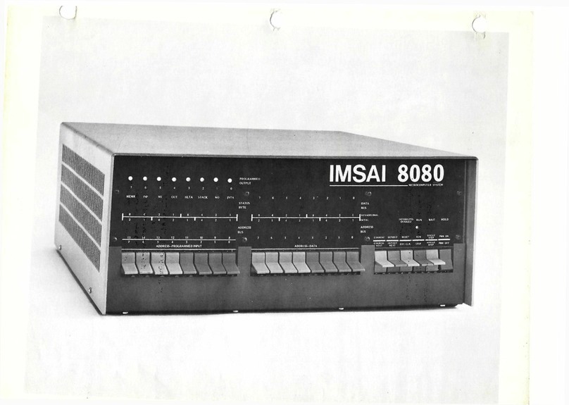
Imsai CP-A User manual

IMSAI
CP-A
Copyright
©
2002
IMSAI
Division
Fischer-Freitas
Company
Orangevale,
CA
95662
Nade
in
the
U.
S.
A.
All
rights
reserved
worldwide

CP-A
Functional
Description
Revision
1
CP-A.
FUNCTIONAL
DESCRIPTION
The
CP-A
board
is
the
operator's
panel
for
the
IMSAI
8080
System.
It
includes
operator
switches,
indicator
lights
and
all
logic
necessary
to
operate
the
IMSAI
8080
System.
The
panel
is
completely
self-contained
and
plugs
into
the
back
plane's
100
pin
edge
connector.
With
this
design
it
is
not
necessary
to
mount
the
CP-A
at
the
front
of
the
cabinet.
Instead,
the
board
can
be
plugged
(via
an
extender
card)
into
any
available
slot
in
the
back
plane.*
A
full
set
of
16
address
switches
and
6
control
function
switches
accept
operator
control
and
input.
LED
in-
dicators
are
provided
for
the
16
bít
address
bus,
the
8
bit
data
bus,
the
8
bit
status
byte
(control
indicators
for
INTERRUPTS,
ENABLED,
RUN,
WAIT
and
8
bits
of
Programmed
output.
The
CP-A
board
contains
the
logic
necessary
to
drive
the
8
programmed
output
indicators
and
the
logic
needed
to
read
an
8
-bit
input
byte
from
the
high-order
address
switches.
The
DATA
BUS
indicators
are
run
from
the
bi-directional
portion
of
the
data
bus
(via
a
flat
cable
to
the
MPU
board)
and
show
data
either
being
read
or
written
by
the
8080
processor.
The
indicators
on
the
panel
are
wide-angle-view
light
emitting
diodes
mounted
behind
a
contrast-enhancing
acrylic
panel
assembly.
All
indicators
and
switches
are
explicitly
marked.
The
photographically
produced
labels
are
very
clear,
protected
by
clear
acrylic,
and
can
never
wear
off.
Bit
positions
are
numbered,
and
binary
bit
values
are
labeled
for
both
hexadecimal
*The
switches
are
included
on
the
front
panel
whether
it
is
mounted
in
the
front
of
the
panel
or
not.

CP-A
Functional
Description
Revision
1
and
octal
formats.
Special
labels
may
be
easily
inserted
to
identify
special
functions
for
the
programmed
output
port.
Switches
on
the
panel
are
high-quality
paddle
switches,
and
are
color-coded
for
easy
and
error
free
use.
For
situations
in
which
it
is
not
desired
to
locate
the
operator's
panel
at
the
cabinet
front
(such
as
use
of
the
IMSAI
8080
as
a
dedicated
controller),
the
CP-A
front
panel
may
be
inserted
(via
extender
card)
into
any
back
plane
slot.
In
this
arrangement,
programs
may
be
easily
tested
and
debugged
without
time-consuming
mounting
and
un-mounting
of
the
front
panel.
For
these
applications,
the
front
slot
of
the
machine
can
be
re-
served
for
the
parailel
I/O
board
with
its
LED
indicators
showing
through
the
front
panel
mask.

CP-A
Theory
of
Operations
Revision
1
THEORY
OF
OPERATIONS
The
CP-A
front
panel
assembly
provides
machine
status
indicators,
user
controlled
switches,
and
control
functions
to
the
IMSAI
8080
operator.
The
CP-A
board
communicates
with
the
MPU-A
microprocessor
and
other
boards
through
the
8080
back
plane
and,
additionally,
connects
(via
16
conductor
flat
cable)
to
the
bi-
directional
data
bus
of
the
8080
microprocessor.
The
CP-A
panel
uses
44
Líght
Emitting
Diodes
as
front
panel
indicators.
Many
of
these
indicators
directly
correspond
to
signal
levels
on
the
IMSAI
8080
back
plane,
and
are
driven
directly
from
the
bus
with
no
intervening
logic.
Indicators
in
this
group
are
the
16
Address
Bus
LED's,
the
8
STATUS
byte
LED's,
the
INTERRUPT
ENABLED
LED,
the
WAIT
LED,
and
the
HOLD
LED
The
8080
microprocessor
chips
bi-directional
data
bus
levels
(provided
by
a
16-conductor
cable)
are
displayed
on
the
DATA
bus
indicators
via
the
74LS04
(low
power
schottky
hex
inverter)
sections.
Also
driven
from
the
bi-directional
bus
is
the
8212
8
bit
latch
used
to
drive
the
PROGRAMMED
OUTPUT
indicators.
The
RUN
indicator
is
driven
directly
from
the
run/stop
flip-flop
(74107)
on
the
CP-A
Board.
The
16
ADDRESS-PROGRAMMED
INPUT
and
ADDRESS-DATA
switches
allow
the
operator
to
place
desired
value
(program,
data,
addresses)
on
the
8080's
bi-directional
bus.
As
shown
on
the
schematic,
these
switches
connect
7405
(open
collector)
inverters
to
the
bus
in
a
wired-
AND
configuration.
Pullup
resistors
on
the
MPU
Board
ensure
that
the
bus
levels
are
all
high
unless
any
inverter
on
any
one
of
the
bus
lines
goes
low.
Thus,
if
an
inverter
goes
low,
(this
condition
will
be
discussed
shortly)
the
address
switch
can
be
used
to
put
either
a
high
or
low
value
on
that
line.
The
function
switches
provide
the
operator
with
direct
control
of
the
microprocessor.
The
RUN/STOP
switch
controls
the
X-READY
line
via
the
RUN/STOP
flip-flop.

CP-A
Theory
of
Operations
Revision
1
If
the
switch
is
set
to
RUN,
on
the
next
falling
edge
of
the
Phase
II
clock,
the
RUN'
and
X-READY
lines
are
set
high.
If
the
switch
is
set
to
STOP,
the
high
STOP
value
and
the
Phase
II
clock
are
NANDed
(.U16)
and
this
value
NANDed
with
the
DATA
OUT
5
bit
(fetch/status)
and
the
PROCESSOR
SYNC
line.
Thus,
when
the
processor
is
fetching
a
new
instruction,
the
RUN/STOP
flip-flop
will
be
reset,
the
processor
X-READY
line
goes
low,
and
the
processor
stops.
Several
CP-A
function
switches
operate
by
providing
the
8080
with
an
instruction,
executing
the
instruction,
and
then
stopping
the
processor
on
the
next
cycle.
The
open
collector
7405's
and
support
gating
put
these
instructions
on
the
8080's
bi-directional
bus.
The
EXAMINE
function
uses
a
jump
instruction
(hex
C3)
followed
by
two
bytes
of
the
address
selected
on
the
front
panel
switches.
This
operation
causes
the
processor
to
jump
to
the
selected
address
and,
then,
the
processor
is
stopped
during
the
next
cycle.
When
stopped,
the
processor
was
reading
the
selected
byte
from
memory
as
if
it
were
going
to
execute
it.
Therefore,
the
processor
stops
with
the
desired
address
displayed
on
the
address
bus
and
the
contents
of
that
address
is
displayed
on
the
data
bus.
If
the
RUN
switch
is
operated
at
this
time,
the
processor
will
continue
to
pull
the
selected
byte
from
memory
and
execute
it.
The
EXAMINE
NEXT
and
DEPOSIT
NEXT
switches
use
similar
schemes
and
the
NO
-OP
(hex
00
or
octal
000)
instruction
to
increment
the
address.
Much
of
the
remaining
logic
of
the
CP-A
is
used
tose-
quence
these
commands
to
provide
the
desired
functions.
The
RUN/STOP
flip-flop
line,
the
SINGLE
STEP
line,
the
EXAMINE
line,
and
the
EXAMINE
NEXT
line
are
alf
input
to
an
OR-gate
controll±hg
the
X-READY
line.
(The
X-
READY
line
must
be
high
for
the
processor
to
run.
Its

CP-A
Theory
of
Operations
Revision
1
function
is
identical
to
the
P-READY
line
used
by
the
memory
and
I/O
boards.
The
X-READY
line
is
reserved
for
use
of
the
front
panel
to
avoid
conflicts
of
two
gates
driving
the
same
backplane
line).
During
each
of
these
functions,
the
processor
is
permitted
to
execute
an
instruction,
and
then
is
stopped
in
the
next
cycle
in
a
manner
similar
to
the
RUN/STOP
flip-
flop
cycle
described
earlier.
For
the
SINGLE
STEP
function,
a
one-shot,
triggered
by
the
SINGLE-STEP
switch,
is
used
to
produce
a
pulse
and
the
trailing
edge
of
that
pulse
is
used
to
set
a
flip-
flop
which
controls
the
SINGLE
STEP
line.
This
permits
the
processor
to
execute
the
present
instruction.
The
SINGLE
STEP
flip-flop
is
reset
by
the
occurrence
of
the
sync
pulse
on
the
following
instruction,
thus
causing
the
SINGLE
STEP
level
to
be
removed
and
the
processor
to
stop
on
the
following
cycle.
The
EXAMINE-NEXT
flip-flop
is
siinilarly
controlled
by
the
leading
edge
of
a
pulse
from
a
one-shot
driven
by
either
the
DEPOSIT
NEXT
or
EXAMINE
NEXT
switch.
The
output
of
the
flip-flop
is
used
both
to
put
the
NO
-OP
(hex
00
or
octal
000)
onto
the
bi-directional
data
bus,
and
aiso
to
provide
the
READY
signal
so
that
the
pro-
cessor
will
execute
the
instruction.
It
is
reset
by
the
sync
pulse
on
the
following
cycle,
thus
stopping
the
processor
again.
The
EXAMINE
function
involves
a
4
-step
sequence
produced
by
two
flip-flops
arranged
as
a
counter.
The
pulse
pro-
duced
by
the
EXAMINE
switch's
one-shot
starts
the
counter
and
on
the
first
count,
the
jump
instruction
is
inserted
on
the
data
bus.
On
successive
counts
of
the
two
bit
counter,
the
lower
and
upper
address
byte
are
inserted
on
the
data
bus
in
turn,
and
on
the
4th
count
(that
is,
when
the
counter
is)nck
to
0),
the
processor
is
again
stopped
by
the
removal
of
the
READY
line.
Thus,
the
EXAMINE
logic
provides
the
processor
with
the
jump
instruction
and
the
two
address
bytes
that
the
processor
expects
after
a
jump
instruction
and

CP-A
Theory
of
Operations
Revision
1
stops
the
processor
during
the
fetch
of
the
designated
memory
byte.
Similarly,
the
DEPOSIT
switch,
when
operated,
prodnces
a
pulse
from
the
DEPOSIT
one-shot
which
is
buffered
to
the
MEMORY
WRITE
line
on
the
backplane.
The
leading
edge
of
this
pulse
also
starts
a
second
one-shot
with
a
much
longer
period
which
puts
the
data
from
the
data
switches
on
to
the
data
bus
for
the
duration
of
the
longer
pulse.
The
DEPOSIT
one-shots
are
triggered
either
by
the
operation
of
the
DEPOSIT
switch
or
by
the
trailing
edge
of
the
DEPOSIT
NEXT
one-shot
so
that
the
DEPOSIT
function
will
operate
at
the
end
of
the
EXAMINE
NEXT
cycle.
The
7427
gate
in
U15.5
is
used
to
insure
that
during
the
time
the
front
panel
is
inserting
any
information
on
the
bi-directional
data
bus,
the
MPU-A
board's
bi-
directional
data
bus
driver
is
not
also
trying
to
drive
the
bus
at
the
same
time.
The
inputs
to
this
gate
are
the
DATA
-ON
line,
the
EXAMINE
NEXT
line
and
the
EXAMINE
line.
These
are
the
three
functions
during
which
the
front
panel
is
transferring
data
or
instructions
to
the
bus.
The
inputs
to
the
7405
open-collector
inverter
bus
drivers
are
the
lines
NO
-OP,
C3,
HAD,
and
LAD.
These
levels
are
ANDed
with
the
PDBIN
signal
so
that
the
information
appears
on
the
bus
during
the
time
the
processor
is
expecting
to
see
it
there.
The
input
port
from
the
high
order
address
switches
is
implemented
simply
by
decoding
the
address
FF
and
ANDing
it
with
the
DBIN
signal
so
that
switch
values
appear
on
the
data
bus
during
the
time
that
the
processor
is
expecting
information
from
the
port
FF.
The
same
address
decode
signal
is
ANDed
witli
the
STATUS
OUT
line
to
enable
the
8212
8
bit
latch
which
drives
the
PROGRAMMED
OUTPUT
indicators.
The
information
on
the
bi-directional
data
bus
is
then
latched
onto
the
output
port
at
the time
of
the
processor
write
strobe.

CP
-A
Theory
of
Operations
Revision
1
The
STATUS
WORD
DISABLE
line
(SSWDSB
i
Pin
53
backplane)
is:gated
to
insure
that
no
conflicts
are
created
between
the
bi-directional
buedrivers
on
thelLIPU
and
CPA
boards.
This
signal
is
contr011ed
by
the
same
gating
_that
places
the
high
order
address
switch
values
on
the
data
bus
for
a
front
panel
(address
hex
FF)
read.
The
.
STATUS
WORD
DISABLE
line,
Pin
53
in
the
backplane,
is
ale°
run
by
the
signal
which
puts
the
high
order
addreSs
switches
onto
the
data
bus
for-the
port
FF
read
instruction
so
that
the
bi-díredtional:data
bus
is
not
being
driven
by
the
bidirectional
driVete::On
the
MPU
board
at
the
Same
time
that
the
frOnt,panel
is
insert-
ing
the
switch
inforMatiOn
on
the
data
buš..
The
RESET
switch
diredtly
gtounds
the
RESET
line
on
thé
backplane
which
is
detedtéd
by
the
MPU
board
and
pro-
cessed
to
form
a
RESET
pulse
which
re-appears
on
the
backplane
as
a
Power
On
Clear.
When
the
RESET
switch
is
thrOwn
.-
c:›EXTERNALCLEAR,
the
switch
directly
grounds
the
EXTERNAL
SWITCH
line
on
the
backplane.
There
is
á
:diode
between
thé
RESET
line
and
the
EXTERNAL:CLEAR
line
siothat
duting
a
reSet
operation
an
EXTERNAL
CLEAR
is
aleo
generated.


11;;;41'.190;M:
I
:4
•
>5
81.1,§4
&&&&
at,
1
,11
5
1
1
.
1
,
m
7,;;;0
--""
•
%1
op
g
-
".~
,
;
á
,
CP-A
R
EV
-4:

BOARD:
CP-A
ITEM
IMSAI
CP-A,
Rev.
4
Parts
List
QUANTITY
DESCRIPTION/IDENTIFYING
MARKS
PART
#
Solder
15-0000001
10'
Heat
Sink
16-0100002
1
Thermalloy/5106B-14
SCrew
20-2203001
22
43:14"
Slotted
Hex
Head,
Self-Tapping,
Type
A
Sheet
Metal
Screw
20-3203001
2
#63c14
Self-Tapping
Sheet
Metal
Screw
20-3302001
1
6-32x5/16"
Phillips
Pan
Head
Machine
Screw
20-3916002
8
6-32x1la"
Button
Head
Allen
Machine,
Black
Nut
21-3120001
1
6-32
Hex
Lockwasher
21-3350001
1
#6
Internal
Star
Lockwasher
Spacer
21-3600001
8
46x14"
White
Nylon
Spacer
21-3600002
8
7/16"
White
Nylon
Switch
26-1500001
8
Blue
Paddle
Switch,
on/none/on
Switch
26-1500002
8
Red
Paddle
Switch,
on/none/on
Switch
26-1500003
2
Red
Paddle
Switch,
momentary
Switch
26-1500004
3
Blue
Paddle
Switch,
momentary
Switch
26-1600001
1
Red
Rocker
Switch,
on/none/on
Resistor
30-3220362
44
220
Ohm,
k
Watt/red,
red,
brown
Resistor
30-4100362
9
IK
Ohm,
lží
Watt/brown,
black,
red
Resistor
30-5470362
6
47K
Ohm,
1
4
Watt/yellow,
violet,
black
Resistor
30-6270362
1
270K
Ohm,
1
4
Watt/red,
violet,
yellow
Capacitor
32-2000110
2
.001uP
Disk
Ceramic
Capacitor
32-2001010
1
.01uF
Disk
Ceramic
Capacitor
32-2010010
17
.1uF
Disk
Ceramic
4
-
15

CP-A,
Rev.
4
Parts
List
IMSAI
rTEM
PART
#
Capacitor
Diode
LED
8T97
7400
7402
7404
74LSO4
7405
7410
74LS10
7427
7430
74LS30
7805
8212
74107
74123
QUANTITY
DESCRIPTION/IDENTIFYING
MARKS
32-2233070
2
33uF
Tantalum
35-1000006
1
Signal
Diode/1N914
35-3000001
44
Light
Emitting
Diode/red
36-0089701
1
Rex
Tri
-State
Buffer/N8T97B
36-0740001
2
Quad
2
Input
NAND/SN7400N
36-0740201
2
Quad
2
Input
NOR/SN7402N
36-0740401
1
Rex
Inverter/SN7404N
36-0740402
2
Rex
Inverter
(Low
Power
Schottky)/SN74LSO4N
36-0740501
5
Rex
Inverter
Open
Collector/SN7405N
36-0741001
1
Triple
3
Input
NAND/SN7410N
36-0741002
1
Triple
3
Input
NAND
(LPS)/SN74LS10N
36-0742701
1
Triple
3
Input
NOR/SN7427N
36-0743001
1
8
Input
NAND/SN7430N
3670743002
1 8
Input
NAND
(LPS)/SN74LS3ON
36-0780501
1
5V
Positive
Volt
Regulator/MC7G05CP
36-0821201
1
I/O
Port/P8212/S1002
36-7410701
3
Dual
J
-K
Flip
Flop
With
Clear/SN74107N
36-7412301
3
Dual
Monostable
Multivibrator,
Retriggerable
with
Clear/SN74123N
Cable
Assembly
91-0400001
PC
Board
Plastic
Panel
93-3010006
Plastic
Panel
93-3010007
Bracket
Photo
Mask
93-3010015
Paper
Backing
93-3010016
4
-
16
1
Cable
K
Assembly
92-0000002
1
CP-A,
Rev.
4
1
Clear
Plastic
Panel
1
Red
Plastic
Panel
93-3010011
1
Switch
Bracket
1
1

CP-A
Rev.
4
Assembly
Instructions
CP-A
Rev.
4
ASSEMBLY
INSTRUCTIONS
1)
Unpack
your
board
and
check
all
parts
against
the
parts
lists
enclosed
in
the
package.
2)
If
gold
contacts
on
the
edge
connector
appear
to
be
corroded,
use
pencil
eraser
to
remove
any
oxidation.
NOTE:
Do
not
use
Scotchbright
or
any
abrasive
material
as
it
will
remove
the
gold
plating.
LED
INSTALLATION
3)
For
a
professional
appearing
finished
CP-A
Board
two
items
in.
the
assembly
are
important:
first,
the
mounting
of
the
LED
indicator
lamps,
and
second,
the
mounting
of
the
paddle
switches.
Care
is
necessary
in
the
mounting
of
both
of
these
items
to
insure
evenly
spaced,
sťraight
line
rows
of
compon-
ents.
If
they
are
assembled
carefully,
the
panel
will
have
a
professional
appearance.second
to
none.
If
these
two
items
are
assembled
haphazardly,
the
panel
will
function;
however,
.
it
will
have
a
distinctly
less
than
workmanlike
appearance.
For
maximum
ease
in
uniform
assemblinq,
the
LED
indicator
lamps
should
be
installed
on
the
board
first,
before
any
other
compon-
ents
have
been
installed.
They
should
not
be
pushed
fully
against
the
board,
but,
rather,
should
be
set
up
approximately
1/8
inch
to
place
them
closer
behind
the
acrylic
panel
mask;
this
provides
for
a
greater
viewing
angle
during
panel
operation.
A
small
easv-to-make
jig
is
extremely
useful
in
accurate
pos-
itioning
of
the
LEI/indicators.
This
mounting
aid
consists
of
1/8
inch
thick
material.
A
piece
of
1/8
inch
plastic,
al-
uminum
or
masonite,
or
two
pieces
of
1/16
inch
material
such
as
vector
board
or
old
printed
circuit
board
make
ideal
jigs.
A
3/4
square
inch
piece
of
the
1/8
inch
material,
or
two
of
the
1/16
inch
material
should
be
cut
and
a
narrow
slot,
such
as
would
be
produced
by
a
hacksaw
or
coping
saw
blade,
cut
into
one
side
a
little
bit
past
the
center.
As
each
light-
emitting
diode
is
installed
in
the
board,
leads
can
be
inserted
through
the
short
slot
čut
into
this
piece
and
then
through
the
board
and
the
LED
should
be
pushed
up
haÉd
against
the
1/8
inch
piece
so
that
its
base
sits
flat
and
it
will
be
held
accurately
1/8
inch
awav
from
the
surface
of
the
front
panel
board.
The
lead
should
be
soldered
from
the
back
while
some-
one
is
holding
the
LED
against
the
mounting
aid
from
the
front.
The
mounting
aid
can
then
be
slipped
out
from
under
the
LED.
Take
care
that
every
LED
is
mounted
in
the
correct
direction
with
the
cathode
down
towards
the
100
pin
edge
connector
at
A
-

CP-A
Rev.
4
Assembly
Instructions
,the
bottom
of
the
board.
The
cathode
can
be
recognized
by
its
proximity
to
the
flat
side
on
the
base
of
the
light
emitting
diode
4)
Insert
and
solder
each
of
the
forty-four
red
LED's
at
locations:
LOO
through
LO7
LAO
through
LA15
LDO
through
LD7
LSO
through
LS7
LIE,
ŽHD1,-LRN,
LWT
RESISTOR
INSTALLATION
5)
Insert
and
solder
each
of
the
forty-four
220
ohm
k
watt
resistors
(red/red/brown)
R16
through
R59.
See
Assembly
Diagram
for
location.
6)
Insert
and
solder
each
of
the
six
47K
ohm
k
watt
resistors
(yellow/
violet/orange)
R3,_
R4,
R5,
R8,
R9;
and
R12.
See
Assembly
Diagram
for
location.
7)
Insert
and
solder
one
270K
ohm
1
4
watt
resistors
(red/violet/yellL
Rl.
See
Assembly
Diagram
for
location.
8)
Insert
and
solder
each
of
the
nine
1K
ohm
14
.
watť_resistors
(brown/
black/red)
R2,
R6,
R7,
R10,
R11,
Ri3Fthrough
R15,
and
R60.
See
Assembly
Diagram
fór
location.,
IC
INSTALLATION
9)
Insert
and
solder
each
of
the
two
7400
IC's
at
locations
U14
and
U25.
10)
Insert
and
solder
each
of
the
two
7402
IC's
at
locations
U13
and
U16.
11)
Insert
and
solder
the
one
7404
IC
at
location
U10.
12)
Insert
and
solder
each
of
the
two
74LSO4
IC's
at
locations
U8
and
U15.
13)
Insert
and
solder
each
of
the
five
7405
IC's
at
locations
Ul,
U3,
U4,
U6,
and
U7.
14)
Insert
and
solder
the
one
7410
IC
at
location
U12.
15)
Insert
and
solder
the
one
74LS10
IC
ať
location
Ull.
16)
Insert
and
solder
the
one
7427
IC
at
location
U15.5.
4
-
18

CP-A
Rev.
4
Assembly
Instructions
17)
Insert
and
solder
the
one
7430
IC
at
location
U21.
18)
Insert
and
solder
one
74LS30
IC
at
location
U9.
19)
Insert
and
solder
each
of
the
three
74107
IC's
at
locations
U18,
U19,
and
U22.
20)
Insert
and
solder
each
of
the
three
74123
IC's
at
locations
U17,
U20,
and
U23.
21)
Insert
and
solder
the
one
8T97
IC
at
location
U24.
22)
Insert
and
solder
the
one
8212
IC
at
location
U5.
DISCRETE
COMPONENT
INSTALLATION
NOTE:
Lead
allowance
on
all
capacitors
must
be
long
enough
to
allow
them
to
be
flattened
(or
laid
down)
flush
on
the
board
or
chip
to
facilitate
front
panel
mounting.
23)
Insert
and
solder
each
of
the
seventeen
.luf
capaci-
tors
at
locations
Cl,
C2,
C5,
C6,
C7,
and
Cll
through
C22.
C2,
C3,
C5,
C6,
and
C7
should
be
laid
down.
24)
Insert
and
solder
each
of
the
two
.001
uf
capaci-
tors
at
locations
C3
and
C8.
25)
Insert
and
solder
the
one
.01
uf
capacitor
at
location
C4.
26)
Insert
and
solder
the
two
33
mf
25
volt
tantalum
capacitors
at
locations
C9
and
C10.
NOTE:
Observe
polarity
as
marked
on
board.
27)
Insert
and
soláer
the
1N914
diode
at
position
CR1.
REGULATOR
AND
BEAT
SINE<
28)
Before
installing
heat
sink
bend
all
the
heat
sink
fins
horizontally
(outward)
to
facilitate
front
panel
mounting.
The
middle
fin
located
on
the
right
band
side
of
the
board
(when
mounted)
should
be
brokeň
off
or
bent
inward
in
order
to
allow
space
for
the
INTERRUPT/ENABLE
LED
(LIE)
to
be
seen
through
the
front
panel.
4
-
19

CP-A
Rev.
4
Assembly
Instructions
29)
To
instáll
the
regulator
and
heat
sink
first
bend
the
7805
regulator
leads
at
90
degree
angles
to
a
length
which
allows
their
insertion
into
the
hole
pattern
of
the
CP-A
board.
Then
place
heat
sink
as
shown
in
Assembly
Diagram
and
insert
regulator
as
described
above.
Use
a
#6
screw
on
the
component
side
of
the
board
and
lockwasher
and
nut
on
the
solder
side
of
the
board.
Tighten
the
screw
care-
fully
to
insure
proper
alignment
of
the
heat
sink
to
prevent
shorting
to
adjacent
traces.
CP-A
TO
MPU-A
INSTALLATION
30)
Using
the
16
conductor
ribbon
cable
with
16
pin
3M
dual
inline
connector,
insert
one
end
into
the
hole
pattern
U2
from
the
back
side
of
the
CP-A
board
so
that
it
can
be
soldered
from
the
front
(component
side)
of
the
CP-A
board.
The
cable
should
be
mounted
so
that
it
extends
upward
from
the
top
of
the
chassis
when
the
board
is
mounted.
SWITCH
INSTALLATION
NOTE:
There
are
three
tyoes
of
switches
included
for
installation
on
the
front
panel
(disregarding
color).
They
include:
A.
One
2
position
red
rocker
switch.
This
is
the
AC
power
switch.
B.
5
momentary
3
position
with
spring
return
to
center
paddle
switches
identified
by
the
lack
of
a
Nipple
(raised
portion)
on
the
front
of
the
switch
mounting
tab.
C.
16
2
position
no
spring
return
paddle
switches.
NOTE:
Temporarily
plug
on
the
CP-A
Board
while
soldered
to
help
insure
the
PC
Board
and
switch
a
100
pin
edge
connector
switches
are
being
proper
spacing
between
bracket.
31)
The
last
step
is
the
assembly
of
the
switches
and
the
switch
mounting
bracket.
Note
that
the
front
panel
includes
switches
whether
mounted
in
the
front
of
the
cabinet
or
not.
The
POWER/ON/OFF
Rocker
Switch
mounts
at
the
extreme
right
switch
position.
The
Paddle
Switches
are
provided
in
both
two-position
and
center-off
spring
return
types.
The
two-position
switches
are
used
for
the
ADDRESS-DATA
and
ADDRESS
PROGRAMMED
INPUT
location
while
the
center
off-
spring
return
are
used
for
the
Control
Functions.
4
-
20

CP-A
Rev.
4
Assembly
Instructions
32)
When
the
entire
row
has
been
spaced
accurately,
the
board
should
be
turned
over
and
a
center
switch
should
be
soldered
in
place
taking
care
that
the
board
is
not
bowed
towards
or
away
from
the
switches.
When
the
board
is
positioned
correctly,
there
will
be
a
smalt
space
approximately
3/64
inch
or
slightly
under
1/16
inch
between
the
bottom
of
the
switch
and
the
front
of
the
front
panel
board.
The
two
end
switches
should
be
similarly
checked
to
make
sure
that
the
spacing
to
the
board
is
correct
and
soldered
in
place,
and
then
one
switch
each
at
the
positions
checked
as
to
spacing
from
the
board
and
soldered
into
place.
Then
the
remainder
of
the
switches
can
be
soldered.
Examine
visually
for
solder
splash
or
bent/unsoldered
pins.
PANEL
ASSEMBLY
Refer
to
the
diagram
to
see
how
the
clear
front
acrylic
piece,
the
photograph
mask,
the
die
cut
paper
backup
and
the
red
acrylic
panel
are
assembled
in
sequence
with
the
6/32
x
1;1
inch
button
head
screws.
BUTTON
HEAD
SCREWS
r
SWITCHES
CPA
BOA
RD
7/1
6°
SPACE
R5
PEM
NUT
PEM
NUT
W
.
SPACERS
CLEAR
ACRYLIC
FILM
MASK
WHITE
PAPER
MASK
1VITH
CUTOUT
Ť
CHASSIS
-1
PIECE
8
I
I I
I I
L
21

CP-A
Rev.
4
Assembly
Instructions
Both
the
Photographic
mask
and
the
paper
backup
sheet
should
.
be
trimmed
to
size
afterassernbly.
Marks
are
provided
on
both,
and
they
should
be
cut
out
carefully
using
a
straight
edge
and
a
very
sharp
knife
againsť
a
wooden
cutting
board.
Scissors
may
be
used
if
a
guide
line
is
first
drawn
on
the
sheets.
The
8
holes
for
the
assembly
screws
should
be
cut
out
on
the
mask
and
the
paper
sheet
as
indicated
in
the
diagram.
Then
the
protective
paper
may
be
removed
from
the
two
acrylic
sheets
and
the
sandwich
assembled
carefully.
Avoid
getting
duste
caught
in
between
any
of
the
pieces.
A
soft
lint-free
rag
verv
slightly
moistened
can
be
an
aid
in
cleaning
any
dust
off
plastic
or
file
surfaces.
When
the
acrylic
pieces,
film
and
paper
have
been
assembled,
eight
7/16
inch
spacers
may
be
slipped
over
the
screws
and
then
the
whole
assembly
inserted
through
the
mounting
holes
on
the
CP-A
board.
Take
care
that
there
is
no
interference
from
any
component
standing
too
high
and
that
the
acrylic
panels
sit
down
completely
on
the
7/16
inch
spacers
against
the
board.
Eight
i
inch
spacers
can
then
be
slipped
over
the
screws
behind
the
CP-A
board
and
eight
#6
nuts
and
lockwashers
can
be
put
on
ťo
hold
the
sandwich
together.
The
panel
board
should
now
be
ready
to
plug
in
and
use.
If
the
board
is
going
to
be
assembled
in
the
front
location
of
a
cabinet,
to
serve
as
a
permanent
front
panel,
the
eight
nuts
should
be
removed
at
this
time.
Install
the
cap
screws
in
the
PEM
nuts
in
the
front
panel
sheet
metal.

CP-A
User
Guide
Revision
1
USER
GUIDE
The
CP-A
board
contains
no
user
option
jumpers
or
any
other
special
connections
that
must
be
made
to
use
the
board.
If
the
panel
is
mounted
in
the
IMSAE8080
cabinet
then
the
power
on/off
switch
should
be
con-
nected
using
a
separate
wire
to
the
power
supply
section
as
described
in
the
Power
Supply
documentation.
If
the
panel
board
is
not
going
to
be
mounted
in
the
cabinet,
then
the
power
switch
should
not
be
connected.
In
this
case,
the
power
switch
on
the
inside
or
on
the
back
of
the
cabinet
would
be
used
for
controlling
power
to
the
IMSAI
8080.
Panel
installation
requires
a
backplane
slot.
The
panel
may
be
plugged
directly
into
the
front
slot
of
the
mother
board
(with
the
mounting
screws
from
the
acrylic
face
plate
assembly
extending
through
the
metal
panel
immed-
iately
behind
and
secured
with
lock
washers
and
nuts)
or
plugged
on
an
extender
card
into
any
location
in
the
back
plane.*
The
16
pin
DIP
plug
on
the
end
of
the
flat
cable
must
also
be
inserted
into.
the
corresponding
socket
in
the
upper
right
hand.corner
of.the
MPU-A
board.
Only
one
front
panel
should
be
plugged
into
the
bus
at
any
time
to
avoid
conflicts
between
multiple
driving
sources
on
the
same
signal
lines
for
some
of
the
control
lines
between
the
front
panel
and
the
system
bus.
The
front
panel
is
now
ready
to
operate.
The
16
ADDRESS-DATA
and
ADDRESS-PROGRAMMER
INPUT
switches
are
2
position
paddle
switches
and
represent
a
()
in
the
down
position
and
a
1
in
the
up
position.
The
switches
are
provided
in
two
colors,
and
can
be
arranged
either
in
color
groups
of
four
to
assist
programming
ín
hexa—
decimal
or
color
groups
of
3,
3
and
2,
to
aid
in
octal
programming.
The
iow
order
byte
of
address
switches,
serve
to
enter
into
memory
either
data
or
program
instructions.
Theše
switches
are
labeled
ADDRESS-DATA
0
through
7.
Each
byte
of
data
or
program
that
is
to
be
entered
from
the
front
panel
is
set
into
these
switches
after
the
approp-
riate
address
has
been
selected
and
entered.
The
switch
*switches
should
be
íncluded
whether
the
front
panel
is
mounted
in
the
front
of
the
cabinet
or
not.
4
-
23

CP-A
User
Guide
Revision
1
positions
are
not
indicated
on
the
indicator
lights
until
the
information
is
deposited
in
memory.
At
that
time
the
information
from
these
switches
appears
on
the
data
bus.
The
high
order
byte
of
address
switches
is
labeled
ADDRESS-PROGRAMMED
INPUT
and
these
switches
can
be
read
by
the
program
as
input
port
position
hex
FF
or
octal
377.
The
additional
labels
O
through
7
are
provided
above
these
switches
to
assist
in
inter-
preting
the
switch
positíons
when
being
used
as
an
input
port.
The
position
of
these
switches
does
not
appear
in
the
indicators
until
the
input
instruction
from
position
FF
is
executed,
during
which
ěxecution
time the
switch
positions
appear
on
the
data
bus
as
it
is
being
read
into
the
8080
processor.
The
six
control
switches
are
grouped
at
the
right
end
of
the
panel.
They
are
center-off
two-position
spring-
return
switches
with
the
exceptíon
of.
the
POWER
ON/OFV
switch,
which
is
a
rocker
type
to
eliminate
accidental
powerdowns.
The
function
switches
are
provided
in
alternating
colors
for
easy
identification
and
to
reduce
operator
error.
The
RUN/STOP
switch
controls
program
execution.
When
the
switch
is
pushed
to
the
RUN
position,
a
control
signal
is
sent
to
the
processor
board
and
enables
it
to
start
or
continue
executing
program
instruction
beginning
in-the
location
indicated
at
that
time
in
the
address
bus
lights.
When
the
address
switch
is
depressed
to
the
STOP
position,
this
enable
signal
is
removed
from
the
processor
board
at
the
beginning
of
the
next
instruction
cycle
so
that
the
processor
will
stop
executing
during
the
fetch
cycle
for
that
follow-
ing
instruction.
When
the
processor
is
enabled
to
RUN,
the
RUN
light
above
the
RUN/STOP
switch
will
be
lit.
When
the
processor
has
been
stopped,
the
WAIT
light
to
the
right
of
the
RUN
light
will
be
lit.
During
normal
operation,
the
RUN
light
will
be
on
full
and
the
WAIT
light
will
be
on
partially,
the
exact
amount
depending
on
how
many
wait
cycles
are
required
by
the
memory
and
peripheral
devices
being
run
by
the
processor
at
the
moment.
4
-
24
Table of contents
Other Imsai Computer Hardware manuals
Popular Computer Hardware manuals by other brands

Poppstar
Poppstar M.2 NVMe Instructions for use
Dini Group
Dini Group DNBFC_S12_PCIe Hardware manual
Rockford Fosgate
Rockford Fosgate 3SIXTY.3 Installation & operation guide
AXIOMTEK
AXIOMTEK SBC84620 Series user manual
ekwb
ekwb EK-Nucleus AIO CR360 Vision D-RGB instruction manual
Zoom
Zoom Zoom player 3000 Operation manual

Phytec
Phytec phyCORE-i.MX 8M Mini quick start guide
AEB
AEB COBRA AEB510N Fitting Instructions and Warranty Workbook

Intel
Intel SL6NQ - Xeon 2.4 GHz/533MHz/512 KB CPU Processor... specification

Pneumercator
Pneumercator MODBUS RTU RS-485 instruction manual

McIntosh
McIntosh MX160 owner's manual

SIIG
SIIG 104-0487A Quick installation guide
