inaa PVT User manual

PVT Hybrid Solar Panel
Electricity/Hot Water
INSTALLATION MANUAL
V1.0
DINEN 12975-1:2006-6
DINEN 12975-2:2006-6
1.
Introduction
1.1.
General safety instructions
Please read this installation manual thoroughly and in detail in order to be able to fully exploit the
functionality of the product. INAA disclaims all liability for de fetcs and damages that would result from
non-compliance with the installation instructions (improper use, incorrect installation, handling error,
etc.).
IMPORTANT
•
It is important to follow these instructions for personal safety. Improper mounting may cause
serious injury. The end user must keep these safety instructions.
•
The installation, control, commissioning, maintenance and repair of the installation must only
be carried out by qualified personnel.
•
The correct functioning of the installation is only guaranteed if the installation and assembly
have been carried out in accordance with the rules of the art.
CAUTION
•
The entire solar installation must be installed and operated in accordance with recognized
technical rules.
•
All electrical work must be done according to local guidelines.
•
The installation must not be used if it shows signs of damage.
DANGER
•
For installations on roofs, it is necessary to comply with personal safety standards, relating to
roofing and waterproofing work and relating to scaffolding work with safety net by mounting the
respective devices before starting work . Refer to the recommendation published by the national
risk prevention organization.
•
Gloves are compulsory when handling the panels to avoid any risk of injury or burns.
•
Disconnect all connection cables from the power supply before working on the installation.
1.2.
General standards to be observed
To ensure safe, ecological and economical operation, all applicable regional and national
standards, rules and directives must be observed, particularly the international standards
mentioned below:
1.2.1.
Photovoltaic solar standards
•
CEI / EN 61215 1 and 2: Design qualification and approval of crystalline silicon photo
voltaic (PV) modules for terrestrial application.
•
CEI / EN 61730 1 and 2: Qualification for dependability of photovoltaic (PV) modules - part
1: Requirements for construction and part 2: requirements for tests.
1.2.2.
Solar thermal standards
•
EN 12975 1 and 2: General requirements and control method for solar thermal collectors.
•
EN 12976 1 and 2: General requirements and process for testing prefabricated solar thermal
installations.
The installation instructions and safety instructions must be met.
Observe the regulations on the prevention of industrial accidents prescribed by professional
associations, in particular those relating to work carried out on the roof.
2.
General description
2.1
General recommendations
2.1.1.
Handling
INAA modules should be handled like any glass product. To avoid accidents, injuries, or damage
to the module during work, the following precautions must always be observed:
•
Do not step on the modules.
•
Do not drop anything on the modules.
•
Protect the modules from possible scratches on the front and rear sides
•
Do not exert mechanical tension on the connectors.
•
Always lift and transport the modules with both hands and never use the junction box as a
carrying handle.
2.1.2.
Transport
In order not to risk damaging the modules during transport, the following instructions must be
observed:
•
Transport the stacked modules vertically, with a separator supported by the frame of each module.
•
Do not remove the original packaging until the time of installation.
•
Do not apply mechanical pressure to the modules (for example, do not fasten the modules with a
strap, or else do not place any object on the surface of the modules).
2.1.3.
Storage
During storage, to avoid any accident or damage to the modules, the following instructions must be
observed:
•
Store the modules vertically.
•
Do not store modules on the edges, on a corner, or on an uneven surface.
•
Do not place any object on the surface of the modules.
•
When choosing a suitable storage location, make sure that:
The location is dry and cool,
No object can fall on the module and thus damage it.
WARNING
If a INAA module is damaged or broken, it must be replaced. Never install a damaged module.
Pressurized system Portrait panels - 2 lines / Single orientation / 1 column - DN15 or DN26 Portrait links
Pressurized system Portrait panels - 2 lines / Double orientation / 1 column - DN15 or DN26 Portrait links
2.2
Technical considerations
Throughout the year, the system is exposed to external weather and natural conditions (sun, wind,
rain, hail, snow, thunderstorms, dead leaves, dust, bird droppings, etc.) which influence the
performance and service life of the modules. To extend the service life of the modules and ensure
proper operation of the installation, important factors and adjustment parameters must be
considered:
2.3
Angle of inclination
The optimal mounting position of the INAA solar panels corresponds to an angle of incidence of the
sun's rays of 90
°
relative to the surface of the panels (i.e. perpendicular to the panels). To optimize
the output of the installation, the panels must be installed with the optimal orientation and angle of
inclination. These positioning angles depend on the geographic location of the installation and can
be calculated by a qualified solar installer. Wherever possible, the panels of a group must have the
same orientation and the same inclination in order to avoid any underperformance of the system due
to inconsistent productions
INAA recommends a minimum tilt angle of 5 ° from the horizontal to reduce the clogging
effect.
The cleaning frequency should be increased for modules installed with a very low angle of
inclination from the horizontal..
2.4
Wind and snow load
The module has been tested up to a pressure of 5400 Pa negative pressure (snow) and 2400 Pa
in positive or negative pressure (wind) without damage. It thus meets the requirements of
standard IEC / EN 61215 for wind speeds up to 130 km / h.
2.5
System location
The overall yield of the photovoltaic system in series is always limited by the module delivering
the lowest power. Different factors can influence the performance of a module (shading,
different orientations, fouling ...) and these impact the entire system.
Therefore, it is necessary to study the layout to avoid a shading effect on the modules in series.
In addition, all panels must be mounted with the same orientation. It is advisable to align all the
modules to the solar noon, to obtain optimal performance.
INAA suggests installing the modules in areas where the temperatures are between -20 ℃ and
+ 50 ℃,which corresponds to the minimum and maximum monthly average temperatures, in
accordance with IEC 60364-5-51. The extreme operating temperatures of the modules are between -
40 ℃and + 85 ℃.
In regions with heavy snow cover and exposed to strong winds, the modules must be mounted in
such a way as to ensure sufficient nominal resistance and in accordance with local regulations.
Certain operating environments are not recommended for INAA modules, and are excluded from
the INAA Limited Warranty:
•
No panel should be mounted on a site where it may be exposed to direct contact with :
•
salt water
•
acid rain
•
active chemical vapors or any other aggressive environment
•
INAA modules must not be installed near flammable liquids, gases, hazardous materials or on
any type of vehicle.
•
Maximum design altitude of the photovoltaic module ≤2000m.
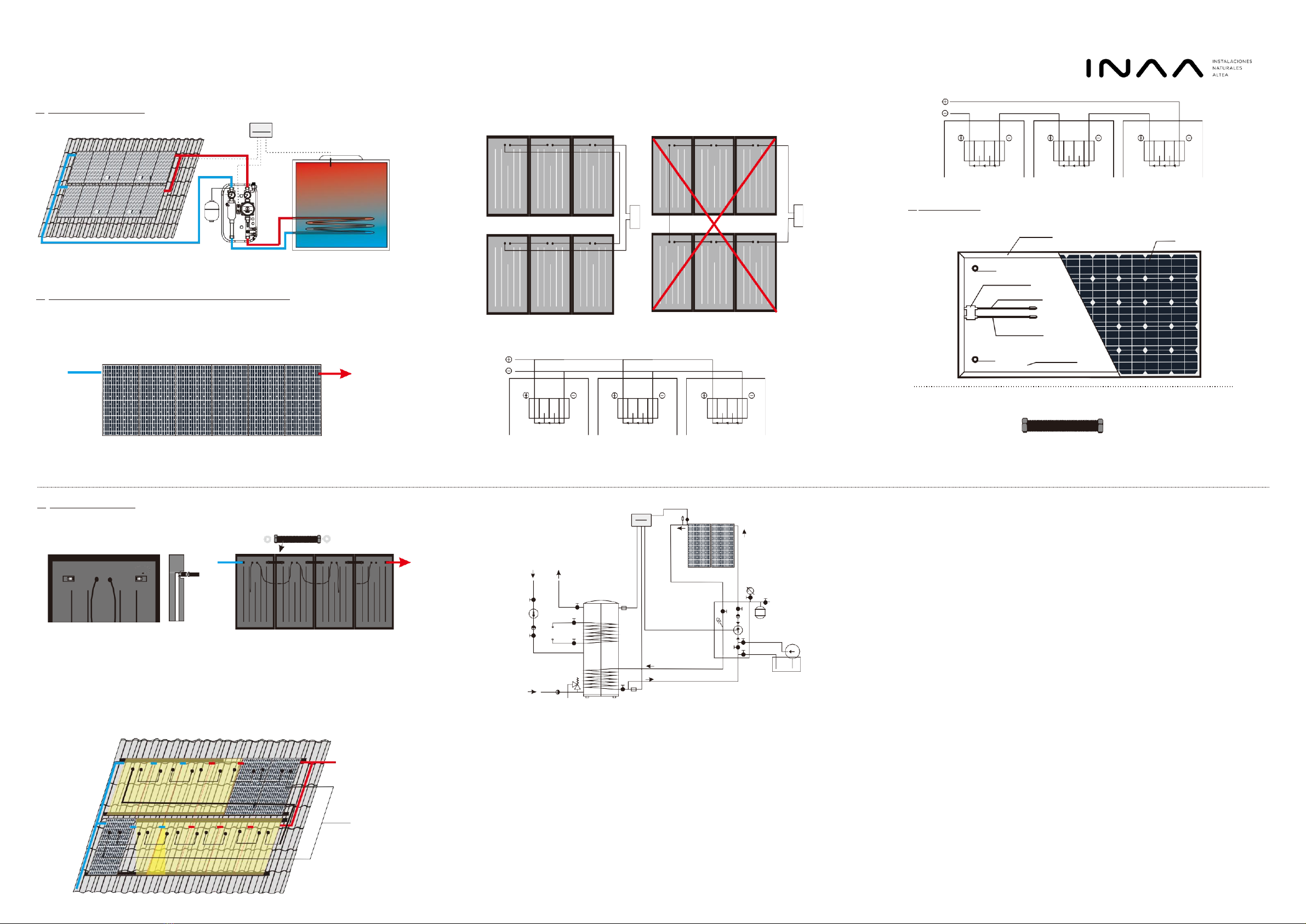
Cells
G1/2" DN/S
Junction box
Connectors
Electric cable
G1/2" DN/S Bottom plate
3.
Working principle Electrical cable loops must be avoided and the surface between the cables must be as small as
possible, as can be seen in the graph below:
4.
Maximum number of panels per hydraulic line
IMPORTANT
To ensure correct filling of the panels during commissioning, the maximum recommended
number of online modules is 6 portrait or landscape
5.
Packing List
5.1
Standard product
Series connestion of modules
Frame
Parallel connection of modules
5.2
Optional accessories
Flexible pipe
6.
PVT Installation
6. 1
Simplified diagram installation of a hydraulic
line with 4 panels in portrait
6. 3
1
- hose 4 - bottom valve
2
- hose 5 - valve
3
- upper valve 6 - pressure measurement
9
7 - solar controller
8 - PVT panel
9 - Filing station
6.5
Venting of the solar installation
After venting the solar installation by means of a filling station and a manual
air escape you should close the air escape valve, in case of an automatic air
escape it is necessary to close the ball valve.
6.6
Insulation work
Insulation work should be done after performing all inspection operations.
Directions!
–
High temperature and weather resistant insulation must be used to insulate
the conduits which are outside the building. If necessary, protect the
insulation against damage caused by birds.
–
High temperature resistant insulation must be used to insulate the conduits
inside the building
6.7
Maintenance and Service
During the maintenance and other kind of work a collector must be placed firmly to exclude the
danger of tripping over and falling down,
It is not allowed to perform any repair and maintenance work under a lifted collector which has
not been protected against casual falling down,
Repair and maintenance work should be done by means of suitable tools and the servicing
personnel should wear protective gloves and shoes,
6.4Filling up the installation by using a filling station
1.
Filling station (9): Connect the hose (1) with the upper valve (3), hose (2)with the bottom valve (4).
2.
Fill up the tank of the filling station with the liquid, open the valve (3 and 4) and run the pump.
3.
Closing the valve (5) will cause the flow through the solar collectors.During filling and venting the
system, you should several times open andclose the vent (5).
4.
Do not turn off the pump until the installation will be completely vent -until from the hose stop
flowing air bubbles.
5.
Open the vent (5) and close the vent (4) and still pump the fluid until the installation will reach the
required pressure, p = 2.5 bar - Pressure measurement (6).
6.
Turn on the controller plug (7) to the network and enable ~ 230V circulation pump in manual mode.
7.
Remnants of the air should be removed automatically by unscrewing the valve manually
8.
In case of decrease or absence of flow unscrew the central screw in the circulating pump and let the
air exhale. Do this exercise until full vent installation.
9.
In the case of pressure drop on the Pressure measurement (6) below 1.5 bar complete up to the to
the required pressure p=2.5 bar.
10.
Disconnect the hose from the filling station from the valves (3, 4)
Before the commencement of maintenance work it is necessary to wait till the temperature of a
collector lowers to such an extent that a risk of getting scalded by hot elements is excluded,
Overhaul of the solar system needs to be done in accordance with warranty recommendations f
or particular elements of the system.
In order to guarantee failure-free operation of the whole system it is recommended to carry out
the following maintenance work at least once a year:
Frost protection
–
check the solar fluid resistance to frost by means of a control device
(refractometer). In case of a significant fall in frost resistance of the solar fluid it should be
replaced and the system must be deaerated once again.
System pressure
–
working pressure in the solar system needs to be checked. After the start-up
period no drop of pressure is permissible.
Expansion vessel –input pressure of the expansion vessel should be checked. To this end,
disconnect the vessel from the system and measure the pressure.
The input pressure should be 2.5 bars.
The control and protection system should also be inspected along with the structure for
supporting and fixing a collector on the roof.
6. 2
solar
controller
7
8
6
auxiliary
heat resource
1
5
3
4
2
This manual suits for next models
1
Other inaa Solar Panel manuals

Popular Solar Panel manuals by other brands

select solar
select solar 05002DK03 installation guide

Lorex
Lorex ACSOL3 Series quick start guide

Dometic
Dometic NDS BS 165WP Installation and operating manual

Rovin
Rovin GH2208 instruction manual

Viking
Viking VSLT240-MH Operation and maintenance manual

Solfex
Solfex IRC 2.1 System installation, commissioning and maintenance manual


Baintech
Baintech BAINTUFF 180W manual

SLK SOLAR
SLK SOLAR PV MODULE Assembly instructions

KANEKA
KANEKA G-SA060 installation manual

GOAL ZERO
GOAL ZERO NOMAD 7 user manual

SunMaxx Solar
SunMaxx Solar ThermoPower VHP Series Installation guide & manual

Autarco
Autarco TBJ Series Installation and operation manual