INAZUMA ITF-30 septem User manual

www. inazuma- online.com
Drum Filters
ITF-30 septem
ITF-50 septem
ITF-80 septem
ITF-120 septem
ITF-160 septem
ITF-240 septem
ITF-30 Biokompakt septem
ITF-50 Biokompakt septem
ITF-80 Biokompakt septem
ITF-120 Biokompakt septem
ITF-160 Biokompakt septem
ITF-240 Biokompakt septem
Control WebCSAV2
Installation and operating instructions
Control WebCSAV2

2
FILTER TECHNOLOGY MADE IN GERMANY
page
1. General information....................................................................................................... 3
1.1. Introduction ...................................................................................................................................................................3
1.2. Important safety notes and warnings ..........................................................................................................................3
1.3. Warning label ................................................................................................................................................................3
1.4. WEEE-registration .........................................................................................................................................................3
1.5. EC declaration of conformity .......................................................................................................................................3
1.6. Utility model protection................................................................................................................................................3
1.7. Alteration and modication..........................................................................................................................................3
1.8. Spare parts ....................................................................................................................................................................3
1.9. Description and function of the product .....................................................................................................................3
1.10. Transport........................................................................................................................................................................4
1.11. Installation guidelines...................................................................................................................................................4
1.12. Warranty ........................................................................................................................................................................5
1.13. Additional information..................................................................................................................................................5
2. Installation and connection........................................................................................... 5
2.1. Before installation .........................................................................................................................................................5
2.2. Case cover .....................................................................................................................................................................5
2.3. Installation: gravity driven setup & water level ..........................................................................................................6
2.3.1. ∙ Connections gravity driven setup ..............................................................................................................................6
2.4. Installation: pump driven setup....................................................................................................................................7
2.4.1. ∙ Connections pump driven setup ................................................................................................................................7
2.4.2. ∙ Pump driven setup: Removal of the overow sheets................................................................................................7
2.4.3. ∙ Important notes on the pump driven setup ...............................................................................................................7
2.5. Installation Control WebCSAV2 / Initial commissioning of the lter ............................................................................8
2.5.1. ∙ Settings / conguration...............................................................................................................................................8
2.5.2. ∙ WebCSAV2 App ............................................................................................................................................................8
2.6. Mounting of the two oat switches..............................................................................................................................9
2.6.1. ∙ Mounting of the oat switch 1 – pump & gravity driven setup.................................................................................9
2.6.2. ∙ Mounting of the oat switch 2 – gravity driven setup .............................................................................................10
2.6.3. ∙ Mounting of the oat switch 2 – pump driven setup ...............................................................................................10
2.7. Magnetic valve for the gutter ush ............................................................................................................................ 11
2.8. Cover switch ................................................................................................................................................................ 11
2.9. Immersion-UVC...........................................................................................................................................................12
2.9.1. ∙ BioKompakt models..................................................................................................................................................12
2.9.2. ∙ Filters without a biochamber ....................................................................................................................................12
2.10. Mounting of the gear protection plate .......................................................................................................................13
2.11. Biological lter material Planet Bio............................................................................................................................13
2.12. Factory settings operating durations / ushes ..........................................................................................................13
2.13. Maintenance................................................................................................................................................................14
2.13.1. ∙ High pressure pump..................................................................................................................................................14
2.13.2. ∙ Prelter ......................................................................................................................................................................14
2.13.3 ∙ High pressure nozzles ...............................................................................................................................................14
2.13.4. ∙ Drum seal...................................................................................................................................................................14
2.13.5. ∙ Screen mesh and stripping brushes.........................................................................................................................14
2.13.6. ∙ Waste ow trench ......................................................................................................................................................14
2.13.7 ∙ Calcication / faults ...................................................................................................................................................15
2.13.8. ∙ Winter operation........................................................................................................................................................15
2.13.9. ∙ Operation in a swimming pond ...............................................................................................................................15
2.14. Technical data..............................................................................................................................................................15
3. Exploded drawing and spare parts list ....................................................................... 16
Certicate of quality................................................................................................................ 17
Service order / repair note...................................................................................................... 19
Index
3
www. inazuma- online.com
1. General information
1.1. Introduction
Congratulations on your new acquisition – a drum lter
made by Inazuma.
To avoid restrictions on function and warranty it is important
to read this manual carefully.
To make sure your lter works as supposed to, we ask you to
follow the manual, the user- guide and additional notes that
are provided with this product, closely.
In the event of emerging questions not addressed in this
manual we ask you to get in contact with your (local) dealer.
If your pond is extremely dirty / there is sludge or
similar deposits on the ground, we recommend
performing a basic cleaning prior to operating the
drum lter..
1.2. Safety notes and warnings
Please store this manual at an accessible location to be
able to address emerging questions about installation,
function and debugging.
It is recommended to keep a copy of this manual close to
the lter so e.g. technicians are able to get quick access to
all informations needed.
1.3. Warning Label
The sign next to this text points out important
warnings or signicant Informations.
1.4.WEEE-registration
iThe WEEE-registration ensures that the producers
are assuming liability for their electrical and electronic
equipment, especially the responsibility for recycling and
disposing of these according to the “ElektroG”.
The Federal Environment Agency of Germany
(Umweltbundesamt) conrms the registration of this product
under the following number:
WEEE-Reg.-Nr. DE 19429673
1.5. EC-Declaration of Conformity
Manufacturer: Inazuma
Johannes Kurzweil GmbH
Eisackstraße 16
DE – 86165 Augsburg
Tel.: +49 821-72 919 72
Fax.: +49 821-72 919 73
E-Mail: info @inazuma-online.com
Internet: www.inazuma-online.com
DeviceType:
Drum lter including electronic control and
high-pressure pump
!
Directives in use:
Machinery Directive: 2006/42/EG,
“Low Voltage” Directive: 2006/95/EG,
General Product Safety Directive: 2001/95/EG
Swiss implementations SR 819.14, SR 930.11 and SR 734.26.
Furthermore, the EN ISO 12100:2010 applies.
The manufacturer declares hereby the conformity of the
product with the safety requirements mentioned above.
1.6. Utility model protection
Gutter ush “Speed Flush” German utility model protection
Nr.20 2015 001 594.8
Cleaning brush “Clean Brush” German utility model
protection Nr.20 2015 001 595.6
1.7. Alteration and modication
We point out that every alteration or modication without
written approval by Inazuma or one of its authorized
suppliers will cause the immediate annulment of the CE
conformity assessment.
Inazuma will not assume liability for damages on persons
or property emerged by unauthorized alterations or
modications.
1.8. Spare parts
Only spare parts provided by Inazuma or one of its
authorized suppliers are approved for installation. In the
event of usage of non-authorized parts the warranty will
expire and Inazuma will not assume liability for damages.
Only use special tooling.
1.9. Description and function
The Inazuma®Drum Filter is a fully automatic, mechanical
lter for removing dirt particles from water circuits
(especially sh and koi ponds).
The drum lter is not suitable for liquids other than water.
!
!
CAUTION
The manufacturer will not assume
responsibility for any damages emerged
by misuse of the product or parts of it or by
non-observance of rules, guides and manuals
provided in this document and additional
documents (including stickers and warning
signs) provided with the product.
Operate the device only when nobody is in the
water!
The device can only be operated, if your house
wiring owns a ground fault circuit interrupter
(GFCI) / residual-current device (RCD) (30 mA
for humid environment) and the power supply
is connected to said system.
It is also recommended to use an overvoltage
protection class D or 3 (depending on your local
guidelines).

4
FILTER TECHNOLOGY MADE IN GERMANY
1.12. Positioning
Your drum lter must be installed in a way, so that it is
always accessible for maintenance work and replacement
of spare parts. For this, a minimum distance of 60 cm at
engine and inlet side, as well as 20 cm at the other two
sides must be observed.
The lter must stand on a rm and stable surface.
Furthermore, this must be a at surface (max 1% slope).
No liability is assumed for damage to the lter caused
by improper transport or the use of improper lifting
equipment.
1.10.Transport
The lter must be transported in an upright position.
Do not lift the product by using force against the engine
skid plate.
The drum lter may only be lifted at the designated load
handling points by using the Inazuma
lifting device.The set is available in
two variants:
for ITF 30 - 80, article number IK6010
for ITF 120 - 240, article number
IK6020
Remove the plugs from the top
corners of the lter. Do not throw
them away.
Guide the lifting bar through the lter
on the left and right side.Thread the
xing rings on the bar inside of the
lter.
Align the rod in the center and tighten
the clamping rings on the housing
wall of the lter.
Now the lter can be lifted by means
of a sling or lifting belt at the 4
suspension points.
No liability is assumed for damage to the lter caused
by improper transport or the use of improper lifting
equipment.
1.11. Installation guidelines
Distances
Your drum lter must be set up so that it is accessible at all
times for the replacement of spare parts and maintenance
work.There is a minimum distance of
60 cm on the engine and inlet side
20 cm on the other two sides
The lter must be freely accessible from the top up to a
height of 1.2 m
Please have the specications in accordance with
this installation plan checked or carried out by e.g.
a construction company / electrician BEFORE
starting the construction / lter installation!
!
If the lter is framed/ obstructed with wood or other
materials, these must be removed by the customer before
starting the service work. Any additional effort due to
non-existent minimum clearances must be borne by the
customer.
Ground
The lter must be on a rm and stable surface.
Furthermore, this must be a at surface (max. 1% incline).
Connection requirements
Operating voltage 230 V
Number of cables / wires x
cross section
1 cable / 3 x 2.5 mm² (valid up to a
maximum cable length of 25 m)
Fuse ratings 1 x 16 A (only use fuses with tripping
characteristic C)
Fault-current circuit breaker 16 A – 30 mA
Grounding to be connected to the ground screw of a
ground pole of min. 50 cm in length and
a cable diameter of 6 mm² (earthing pole
item no. IK6000)
If you have any questions, please contact the Inazuma
customer service onTel. (+49) 821 - 7291972.
The requirements must be carried out according to the
plan. In the event of deviations and the resulting delays or
a renewed travel, Inazuma reserves the right to charge the
additional work.
In the event of non-compliance, we assume no liability for
damage to property or personal injury.

5
www. inazuma- online.com
1.12. Warranty
The 2-year guarantee is a voluntary manufacturer’s
guarantee in accordance with the following guarantee
conditions. In addition, the guarantee conditions apply,
which can be viewed at www.inazuma-online.com.The
customer’s statutory warranty rights remain expressly
unaffected.
Warranty services apply for the specied duration,
calculated from the handover of the product to the
customer (invoice date). Provided warranty services do
not result in an extension of the warranty period or a
new warranty period for replaced or repaired parts.The
additional optional warranty extension for 2 more years
can only be acquired within 6 months after the lter
purchase.
If the item is resold, the guarantee is not transferable.
This guarantee does not apply to commercial use, here a
6-month guarantee applies.
Any changes to the device, control or connecting cables
and plugs will invalidate the guarantee.
The manufacturer is generally not liable for damage
resulting from an accident or improper installation or use
and consequential damage.
1.13. Additional information
ATTENTION
food additives, treatment with salt, use of tools
Numerous food and care products for koi and other shes
contain a high proportion of additives like iron. Please
make sure that all additives in use are classied for use in
combination with stainless steel.
Improper additives, the treatment of sh with salt and the
use of tools made out of steel are likely to cause damages
to the lter system.
Damages caused by improper additives, salt or the use of
inappropriate tools are excluded from warranty.
!
2. Installation and connection
The installation and connection of the drum lter
should only be carried out by qualied personal.
2.1. Before installation
Please examine the product before the beginning of the
installation procedure.
Ensure that neither the product itself nor the wrapping is
damaged.
Make sure that the lter does not contain any objects.
Before commissioning, you must remove
the transport lock (see picture below), or else
mechanical damages might occur.
(TheTransport lock is not included in all models!)
!
!
!
2.2. Case Cover
The case cover of each drum lter model can be mounted
mutually.You can therefore adjust the direction of the
opening to the situation on site.
If you want to mount the cover turned by 180°, the
following order of installation must be followed.
Non-observance will damage the drum screen
(gauze).
This is not subject to the guarantee / warranty!
1. In the rst step, the splash guard (1) must be transferred
to the designated location (2).
2. Only in the next step, the lter cover can be remounted.
You nd all necessary drill holes for the hinges and cover
lockings on opposite sides of the drum lter. For some
models, only one cover locking can be mounted after the
conversion due to their design.
!During installation, make sure that moving parts
of the lter can not be blocked by cables!
1 2
6
FILTER TECHNOLOGY MADE IN GERMANY
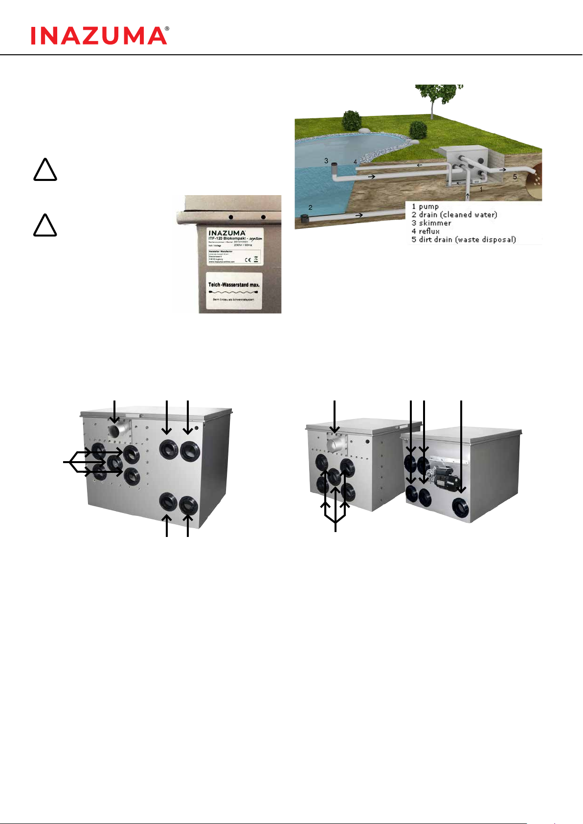
2.3.1. Connections gravity driven setup
*Make sure that the drain reaches a much lower level.The slope will prevent blockages.
Connections gravity driven setup for biochamber lters Connections gravity driven setup – lters without a biochamber
waste water outlet*waste water outlet*
Connections pump
(dry position)
connections for the pump
(immersed)
returns to pond/pool or
external biochamber
inlets
inlets
!
!
2.3. Installation: gravity driven setup &
water level
The lter must be installed on even and solid ground.
After positioning the lter, both axes (longitudinal and
transverse) must be aligned by using a spirit level.
Make sure that none of the tubes puts mechanical
load on the case of the lter.
Make sure that the
lter, arranged in the
gravity driven setup,
is positioned in the
right level within the
water-level.
You can nd a sticker
marking the right level
near the connections
on the front of the
lter.
gravity driven setup

7
www. inazuma- online.com
2.4. Installation pumped version
The lter must be installed on even and solid ground.
After positioning the lter, both axes (longitudinal and
transverse) must be aligned by using a spirit level.
Make sure that none of the attached tubes puts
mechanical load on the case of the lter.
IMPORTANT NOTE FORTHE PUMP DRIVEN SETUP
In a pump driven setup the amount of inlet
connections must be reduced.
Cover all unused inlet connections with caps.
!
!
2.4.1. Connections
pump driven setup
Reux connection:
In the pump driven setup it is
recommended to use anT-pipe/
branch pipe (open to the top)
at the reux connections to
ventilate the run-back line.
pump driven setup
*Make sure that the drain reaches a much lower level.The slope will prevent blockages.
Connections pump driven setup for biochamber lters Connections pump driven setup for lters without a biochamber
waste water outlet *waste water outlet *
close these connections with caps
returns to pond / pool
returns to pond/pool
(only use the top ones)
close the bottom connections with caps
inlets
inlets
2.4.3. Important notes for the pump
driven setup
1.To prevent the loss of water in the event of malfunction,
remove the premounted sheet metal parts and store them.
2. We recommend powering the pumps using an external
system.The Inazuma Control WebCSA
V2 provides this
function. In case of a malfunction or an error, the Control
WebCSA
V2 shuts the pumps down automatically.
In the pump driven setup the oat switch must be
installed in the prechaber of the lter.
!
Pumped version
remove closed sheet metal parts
2.4.2. Pumped version: Removal of the
overow sheets
8
FILTER TECHNOLOGY MADE IN GERMANY
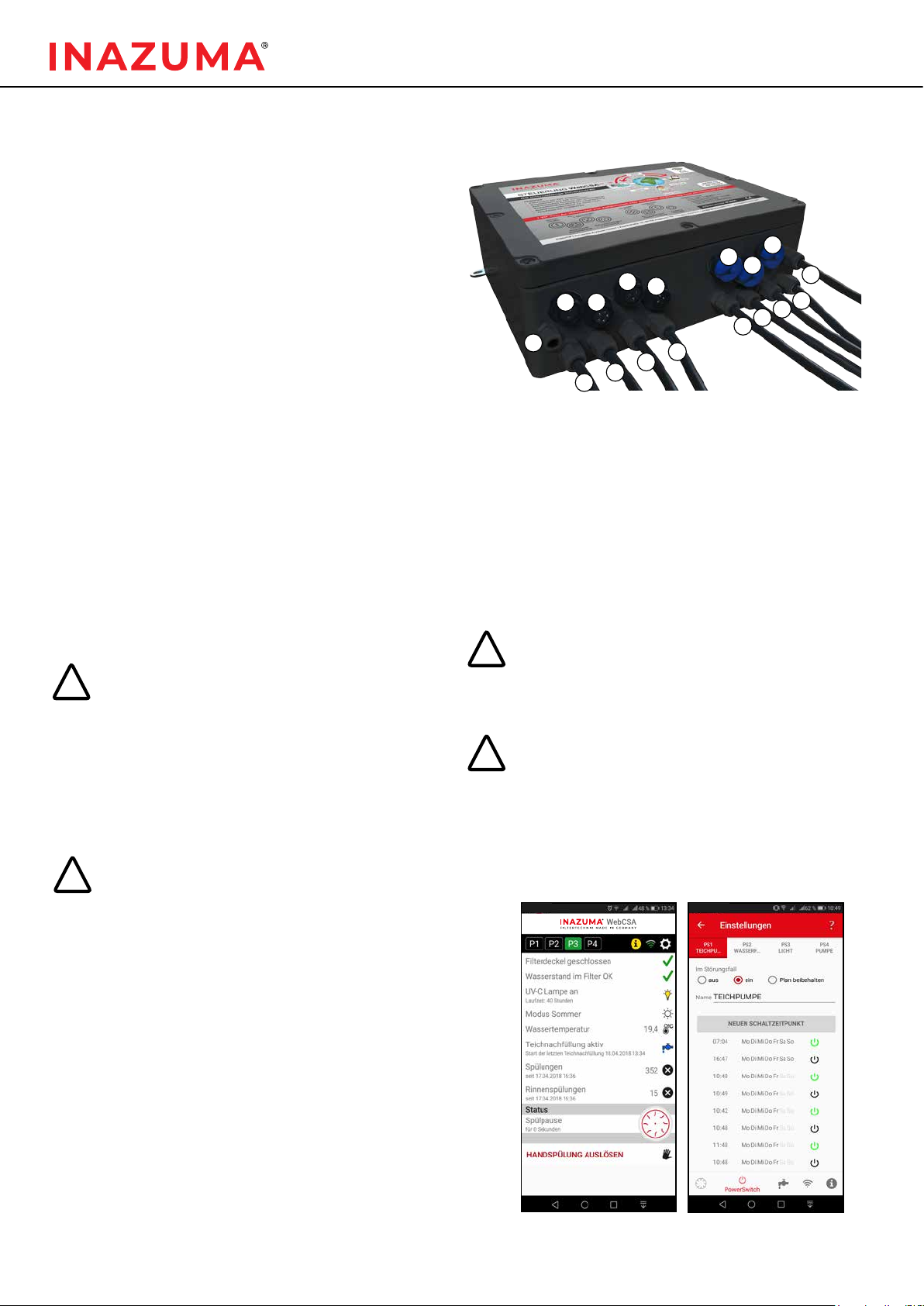
1. Mains Plug
2. Gear motor
3. High pressure pump
4. UVC
5. UVC
6. Power-Switch P4 (optional)
7. Power-Switch P3 (optional)
8. Power-Switch P2 (optional)
9. Power-Switch P1
10. Cable entry for W-LAN
antenna (optional)
11. Cover switch
12. Solenoid valve for gutter ush
13. Float switch 2 (2 oaters)
14. Float switch 1 (1 oater)
15. Temperature sensor (optional)
16. Solenoid valve for water level
regulator (optional)
1 7. water level sensor (optional)
2.5.1. Settings / conguration
The control is delivered without conguration. Before
commissioning, the control must be congured using
an app (available for Android and iOS). Please read the
operating instructions for the control WebCSA V2.
The rinsing process will start automatically depending on
the pollution level of the drum.
When the drum is soiled to a certain level, the oat switch
activates the rinsing process.
The drum lter control is equipped with a malfunction
detector. When a malfunction is detected, the control
reports a malfunction by sending out a beeping sound.
ATTENTION
You have to pay attention to the water level if
you have a pond without an automatic water
rell system. If the water sinks below the level
of the bottom oat switch, the lter will turn off
automatically, or else a continuous irrigation
would occur.
Inazuma offers an automatic pond level regulation
(item no. IK5001)
The drum lter control system should only be
opened by qualied personnel!
There is a danger of electric shock and risk of
injury, as the circuit board is live.
!
!
2.5. Installation Control WebCSA
V2 /
Initial commissioning of the lter
2.5.2. Connections
2.5.3. WebCSAV2 App
Before commissioning the lter, the system must be lled
with water and the cover must be closed.
• Control is splash proof (IP65)
• Protect from direct solar radiation!
• Do not drill any holes into the case, otherwise the
warranty will be lost.
A detailed operating manual for the WebCSA
V2
control, the app and the optional accessories for
the control (power switch, temperature sensor,
pond level regulation) can be downloaded from
our homepage www.inazuma-online.com.
The WebCSA
V2 app can be downloaded in the
google play store and apple app store.
!
!Always disconnect the power plug before
connecting / disconnecting components or
opening the control unit!
1
6
14
2
7
13
17
3
8
12
16
4
5
9
11
15
10

9
www. inazuma- online.com
2.6. Mounting of the two oat switches
The WebCSA
V2 control is supplied with two oat switches..
Mounting float switch 1
in the right area of the prechamber under the solenoid valve
2.6.1. Mounting oat switch 1 (gravity & pumped)
Float switch 2 (2 oaters) is responsible for ushing and
dry running protection.
Float switch 1 (1 oater) detects the water level in the
prechamber.

10
FILTER TECHNOLOGY MADE IN GERMANY
Position of the oat switch and its mounting
In the pump driven setup, the oat switch is already
installed in the waste water section in front of the drum.
The mounting is completely pre-assembled.Therefore,
there is no need to adjust its position.
Upper oat switch:
Responsible for the activation of the emergency shutdown
and protection of non-stop rinsing.
During normal operation of the drum lter it should be
always above the water level. If the upper oat switch gets
pushed upwards by water, the drum lter shuts down and
a fault signal occurs.
In pump mode, we recommend connecting the pond pump
to the Power Switch Outlet No. 1 of the control WebCSA
V2.
In this case, your pond pump (connected to the Power
Switch) will then be switched off in the event of a fault and
the pond will not be emptied.
Bottom oat switch:
Activates the rinsing-process. At the end of every rinsing-
cycle the top ring is supposed to oat towards the bottom
end.
2.6.3. Mounting oat switch 2 (pumped)
Waste water section in front of the drum
Upper oat switch:
Activates the rinsing-process. At the end of every rinsing-
cycle the top ring is supposed to oat towards the top end.
Bottom oat switch:
Activates the emergency shutdown in the event of non-
stop rinsing to prevent a drop of the water level in the
pond/pool.The bottom ring is always supposed to be
under water.
If it falls to the lower stop, the drum lter switches off,
because there is too little water in the pond.
The exact position of the oat switch must be
adjusted individually (slot holes in the mounting).
The height depends on the power of the pump.
Biokompakt-Models:
Pure water area outside the drum
2.6.2. Mounting oat switch 2 (gravity)
!
Filters without biochamber:
Mount float switch here.
Pure water area outside the drum
11
www. inazuma- online.com
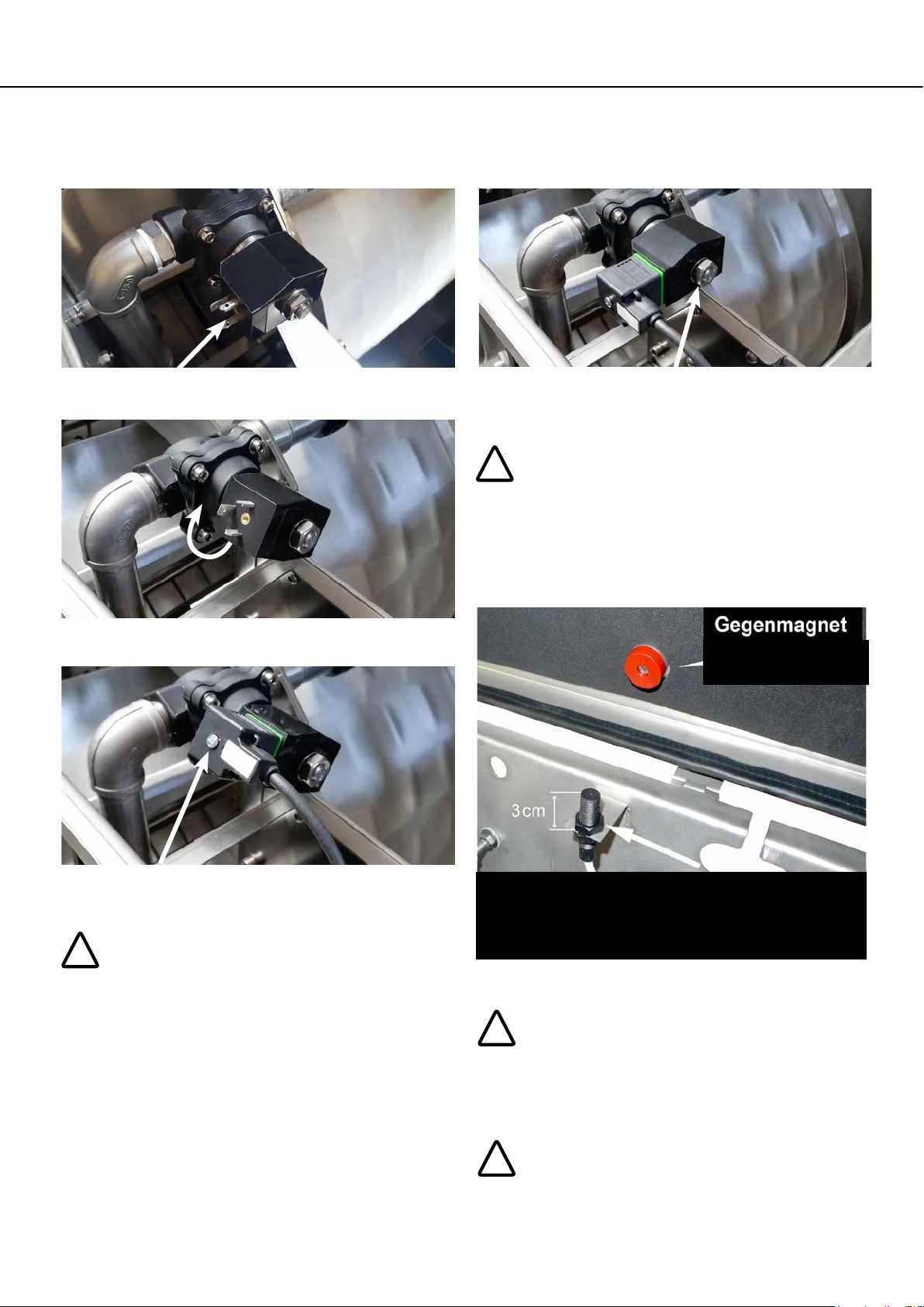
2.7. Installation of the magnetic valve
for the gutter ush
2.8. Cover switch
ATTENTION:
The manufacturer will not assume liability for
damages emerged by misuse of the product or
parts of it or by non-observance of rules, guides
and manuals provided in this document and
additional documents provided with the product.
During maintenance of the drum lter always
unplug the mains plug.
The system will also detect the opening of the
drum lter and will interject the power supply.
Never activate the cover-detection-switch
manually.
!
!
counter magnet
Cover switch
The cover switch must be in a position in which, when the
cover is closed, the gap between it and the counter-magnet is
at most 5 mm wide.
!
!
On delivery, the connection pins of the solenoid valve
head point towards the housing wall.
Loosen the nut on the solenoid valve head and turn it until
the pins point about 30 ° upwards.
Insert the plug of the solenoid valve onto the solenoid
valve head.Then tighten the screw on the back of the
connector.
Now turn the complete solenoid valve back to the starting
position until it is perpendicular to the lter wall.Tighten
the nut on the solenoid valve head rmly.
Make sure that the sealing washer of the screw
and the square housing seal are correctly attached.
IMPORTANT NOTE
Your drum lter is equipped with the Speed Flush
system (rinsing ush). In the default setting of the
controller, your lter performs a ush twice a day.
With the WebCSAV2 app, the number of ushes per
day can be changed.

12
FILTER TECHNOLOGY MADE IN GERMANY
2.9. Mounting of the immersion-UVC
2.9.1. Biokompakt models
All Inazuma drum lters of the septem series have one or more internal brackets for easy installation of immersion
UVC lamps suitable for the Inazuma high-performance duo lamp HD-PRO-50.000 V2.The UVC receptacles are sealed ex
factory with a sealing plug (see Fig. 1).
Assembly:
Depending on the number of UVC lamps, remove the sealing plugs. Insert the immersion UVC into the stainless steel
holder from above. Be careful not to damage the quartz tube.The lamp should now rest with the union nut on the top of
the bracket. Please keep the plugs after installing the UVC lamps (see g. 2).
g. 1 g. 2
2.9.2. Filters without biochamber
g. 1
g. 3
g. 2
All Inazuma septem drum lters have one or several UVC mountings on the inside (suitable for the HD-PRO 50.000 V2
immersion-UVC) (see g. 1)
Assembly:
Insert the immersion-UVC into the mounting until the device reaches the xture. Do this with caution to not damage the
quartz glass pipe.The union nut of the UVC-emmiter should now rest on the mounting (see g. 2)
Depending on the position of the immersion-UVC it might be necessary to remove the nut of the gas pressure absorber
(see g. 3)

13
www. inazuma- online.com
!
2.12. Factory settings operating
durations / ushes
rinsing duration: ca. 12 sec.
rinsing “Speed Flush”: 2 ushes within 24 hours
wave suppression: ca. 20 sec.
automated shutdown after non-stop rinsing
pump driven setup: ca. 10 min.
automated shutdown after non-stop rinsing
gravity driven setup: ca. 30 min.
Explanation of the rinsing process:
There are no guideline values for the number of rinses, this
always depends on the degree of soiling and the pumping
capacity.
In conjunction with the WebCSA
V2 app these and other
parameters can be changed or adjusted.
See also the operating instructions WebCSA
V2
www.inazuma-online.com.
Always unplug the power during any maintenance
work on the drum lter.
The system will also detect the opening of the
drum lter and will stop the power supply.
Never activate the cover switch manually.
2.11. Biological lter material Planet Bio
We recommended the use of biological lter material
Inazuma Planet Bio in following quantities:
ITF-30 BioKompakt septem 150 liters
ITF-50 BioKompakt septem 200 liters
ITF-80 BioKompakt septem 250 liters
ITF-120 BioKompakt septem 300 liters
ITF-160 BioKompakt septem 350 liters
ITF-240 BioKompakt septem 450 liters
Suggestion: At rst, put only half of the lter material into the
drum lter. Add the second half two weeks later.
The weight of the material is tared in such a way, that as soon
as the balls are canonicalized by microorganisms, they oat just
below the water level. In clean condition, just after putting them
into the lter, the balls push each other out of the water.
2.10. Assembly of the engine guard plate
The engine guard plate is inserted from the top of the
already pre-assembled bracket.
Dismantling the screws is not necessary!

14
FILTER TECHNOLOGY MADE IN GERMANY
2.13.2. Prelter
To protect the high-pressure
nozzles, a ne lter is
installed.
Simply rinse the disc lter
under running water. Please
also take care to remove any
contamination between the
individual panes.
2.13.4. Drum Seal
1. Once or twice a year,
especially after winter or a
longer standstill, the seal
of the drum should be
maintained.To do this, use an
ordinary silicone spray.This
prevents sticking of the seal on
the edge of the drum and an
easier startup of the drum.
1. Pull the mains plug of the the control unit, and the motor
connection cable leading to the control unit
2. Empty the lter completely
3. Plug the power plug from the motor into a socket (not
into the control unit)
Attention! Risk of injury due to rotating drum!
4. Spray some silicone spray on the edge of the drum until
it reaches about two turns
5. Disconnect the motor from the mains socket and
reconnect it to the control unit. Power the control unit.
6. Your lter is now ready for use again
!
2.13. Maintenance and care
During maintenance and before opening the lter it is necessary to turn it off and to unplug the power cable.
Otherwise, there will be a heavy risk of injury.
Maintenance: For optimal lter performance we recommend you to perform steps 1 to 5 once a year. Lime-water can
cause a poor cleaning of the mesh and shorter ushing intervals.To counteract that, please note point 2.13.7.
2.13.1. High pressure pump
To protect the high-pressure
pump, a lter sponge is
attached below the high
pressure pump.
To remove the lter sponge,
loosen the screw on the high-
pressure pump, lift it upwards
and remove the lter sponge
at the bottom.
Simply rinse the lter sponge
with clean water, put it back in
and retighten the screw.
2.13.3. High pressure nozzles
To decalcify the nozzles,
please disassemble them and
immerse them completely in
citric acid for about 30 minutes.
If the nozzles are clogged, you
can blow them out or clean
them with a toothbrush. Never
use hard or sharp objects,
such as Cutter knives or steel
brushes.These can damage the
spray nozzles.
2.13.5. Screen mesh and stripping brush
If the mesh is damaged, it can
be changed easily. Depending
on the load and water quality, it
may occasionally be necessary
to clean the mesh. For this see
chapter “Calcication / Fault”.
The stripping brush in the drum
should be checked occasionally
and replaced if necessary.
2.13.6. Waste ow trench
The gutter should, despite
regular gutter ushing, be
checked once a week for any
leftovers or adhering debris.

15
www. inazuma- online.com
2.13.7. Calcication / Fault
Depending on the degree of hardness of the water used in the
pond, there is usually no visible calcication of the mesh. A
common symptom is that the lter almost continuously rinses.
ATTENTION
This maintenance work should only be carried out by
qualied personnel!
ÎTo remove the calcication, we recommend cleaning the
mesh with citric acid.
1. Pull the mains plug of the the control unit, and the motor
connection cable leading to the control unit
2. Empty the lter completely
3. Apply the solution to the mesh with a brush
4. Leave the cleaning solution on for 10 to 15 minutes
5. Now plug the power plug of the engine into a socket (not on
the control) for a short time
Attention! Risk of injury due to rotating drum!
6. Repeat steps 3 to 5 until the entire mesh is treated
7. Rinse the mesh with clear water
8. Reconnect the motor connection cable to the control unit
and power the control unit.
ÎIf the above procedure does not lead to success, please
contact your dealer.
Do not place any tools such as brushes or containers
on the drum.The safety instructions of the cleaning
agent used must be observed!
2.14. Technical data
Materials in use
Stainless steel V4A: case, drum connections, trench etc.
Plastic: seal, rollers, anged housing unit
Motor and control
Power supply control 230 Volt / 50 Hz
Microfuse control 230 Volt / 10 A
Power supply sensor 12 Volt
Power supply cover switch 12 Volt
Power supply motor 230 Volt / 50 Hz
Motor power
0,18 KW (from ITF-30 to ITF-120)
0,36 KW (ITF-160 Biokompakt & ITF-240 Biokompakt)
Temperature range -10 °C – +50 °C
The case of the control elements must be
protected from direct sunlight and other heat
sources.
High pressure pump 230 Volt / 50 Hz
Power 0,6 kW
Hmax 42 m
Qmax 45 l/min
Flow rates (degree of pollution: max. ≤ 10 mg/ℓ)
!
!
!
!If the drum lters are operated with either a ow
rate, that is too high or with very heavily polluted
water, this can lead to extremely frequent rinsing
processes up to self-shutdown of the device
(continuous ushing protection, see factory setting
control times / ushing).
2.13.5. Winter operation
Generally, the operation of the
lter during winter is possible.
You have to make sure, that
the water temperature is
above 4°C (40°F).This can be
achieved by using appropriate
measures (e.g. immersion
heater).They prevent
damages and malfunctions of
the lter.
Ex works, a sealing plug is attached to the underside of
the rinsing drain. It must be unplugged when you are not
operating the lter in winter.
2.13.7. Operation in a swimming pond
Please follow your local guidelines for the operation of a
swimming pond.
Only run the drum lter, when no person is staying
in the water!
We recommend due to safety reasons to turn the
system off completely during bathing.
ITF-30 septem
Biokompakt ITF-50 septem
Biokompakt ITF-80 septem
Biokompakt ITF-120 septem
Biokompakt ITF-160 septem
Biokompakt ITF-240 septem
Biokompakt
pumped 20 m³ / h 30 m³ / h 45 m³ / h 60 m³ / h 80 m³ / h 120 m³ / h
gravity 15 m³ / h 25 m³ / h 35 m³ / h 45 m³ / h 65 m³ / h 100 m³ / h
ITF-30 septem ITF-50 septem ITF-80 septem ITF-120 septem ITF-160 septem ITF-240 septem
pumped 20 m³ / h 30 m³ / h 45 m³ / h 60 m³ / h 80 m³ / h 120 m³ / h
gravity 15 m³ / h 25 m³ / h 35 m³ / h 45 m³ / h 65 m³ / h 100 m³ / h

16
FILTER TECHNOLOGY MADE IN GERMANY
A ( 1 : 3 )
B ( 1 : 3 )
D ( 1 : 3 )
E ( 1:1 )
F ( 1:2 )
A
B
D
E
F
1
1
2
2
3
3
4
4
5
5
6
6
7
7
8
8
9
9
10
10
11
11
12
12
A A
B B
C C
D D
E E
F F
G G
H H
1
A1
Status Änderungen Datum Name
Gezeichnet
Kontrolliert
Norm
Datum Name
Zeichnungsnummer
Bezeichnung
Artikelnummer
Blechstärke
Bl.
mm
ISO 13715
Allgemeintoleranz
ISO 2768 mK
+0,50
+0,05
-0,50
-0,05
Material
12.05.2016 aplatzda
Projekt: Status:
Masse: -
1
3
2
46
5
14
13
12
10
17
11
15
19
16
7
8
9
Lagereinheit innenliegend
Lagereinheit und Antrieb
außenliegend
18
7
9
10
11
12
13
14
15
A ( 1 : 3 )
B ( 1 : 3 )
D ( 1 : 3 )
E ( 1:1 )
F ( 1:2 )
A
B
D
E
F
1
1
2
2
3
3
4
4
5
5
6
6
7
7
8
8
9
9
10
10
11
11
12
12
A A
B B
C C
D D
E E
F F
G G
H H
1
A1
Status Änderungen Datum Name
Gezeichnet
Kontrolliert
Norm
Datum Name
Zeichnungsnummer
Bezeichnung
Artikelnummer
Blechstärke
Bl. mm
ISO 13715
Allgemeintoleranz
ISO 2768 mK
+0,50
+0,05
-0,50
-0,05
Material
12.05.2016 aplatzda
Projekt: Status:
Masse: -
1
3
2
46
5
14
13
12
10
17
11
15
19
16
7
8
9
Lagereinheit innenliegend
Lagereinheit und Antrieb
außenliegend
18
E
A ( 1 : 3 )
B ( 1 : 3 )
D ( 1 : 3 )
E ( 1:1 )
F ( 1:2 )
A
B
D
E
F
1
1
2
2
3
3
4
4
5
5
6
6
7
7
8
8
9
9
10
10
11
11
12
12
A A
B B
C C
D D
E E
F F
G G
H H
1
A1
Status Änderungen Datum Name
Gezeichnet
Kontrolliert
Norm
Datum Name
Zeichnungsnummer
Bezeichnung
Artikelnummer
Blechstärke
Bl. mm
ISO 13715
Allgemeintoleranz
ISO 2768 mK
+0,50
+0,05
-0,50
-0,05
Material
12.05.2016 aplatzda
Projekt: Status:
Masse: -
1
3
2
46
5
14
13
12
10
17
11
15
19
16
7
8
9
Lagereinheit innenliegend
Lagereinheit und Antrieb
außenliegend
18
8
16
5
3
4
A ( 1 : 3 )
B ( 1 : 3 )
D ( 1 : 3 )
E ( 1:1 )
F ( 1:2 )
A
B
D
E
F
1
1
2
2
3
3
4
4
5
5
6
6
7
7
8
8
9
9
10
10
11
11
12
12
A A
B B
C C
D D
E E
F F
G G
H H
1
A1
Status Änderungen Datum Name
Gezeichnet
Kontrolliert
Norm
Datum Name
Zeichnungsnummer
Bezeichnung
Artikelnummer
Blechstärke
Bl. mm
ISO 13715
Allgemeintoleranz
ISO 2768 mK
+0,50
+0,05
-0,50
-0,05
Material
12.05.2016 aplatzda
Projekt: Status:
Masse: -
1
3
2
46
5
14
13
12
10
17
11
15
19
16
7
8
9
Lagereinheit innenliegend
Lagereinheit und Antrieb
außenliegend
18
6
A
1
2
1
2
Inazuma-Infohotline: (+ 49) 821 - 72 91 972
Bestellungen an: vertrieb@inazuma-online.de
Nr. Bezeichnung Art. Nr.
1 Nozzle kit (nozzle, union nut, seal) IK1564
2 Holder for high-pressure nozzle IK1000552
3 Drum tappet
4 Sealing set consisting of 2 x seals and 1 x pressure washer IK1000680
5 Flange bearing including shaft seals for ITF-30 to 240 IK1000679
6 Geared motor for ITF-30 to ITF-120 & Biokompakt models
Gear motor for ITF-160 & 240 Biokompakt
IK2039
IK1801
7 Guide roller set for ITF-30 to 120
Guide roller set for ITF-160 to 240
IK1000681
IK1000682
8 Magnet for lid switch IK1196
9 Gas Springs IK1731
10 Lid seal (sold by the meter!) IK1162
11 Cartridge lter for all drum lters from 2015 IK1577
12 Replacement cover for drum lter ITF-30 from MK V
Replacement cover for drum lter ITF-50 from MK V
Replacement cover for drum lter ITF-80 from MK V
Replacement cover for drum lter ITF-120 from MK V
Replacement cover for drum lter ITF-160 from MK V
Replacement covering for drum lter ITF-240 from MK V
IK1615
IK1616
IK1617
IK1618
IK1677
IK1619
13 Magnetic valve for trough ushing Speed Flush (black head /
actuator)
IK1845
14 Drum seal for all models 30 - 120
Drum seal for all models 160 - 240
IK1180
IK1786
15 Tank screw connection / bushing with thread & seal IK1466
16 Seal for gutter “Speed Flush” from MY 2016 IK1679
Feather key for keyway / drive shaft diameter 25 mm IK1702
Inazuma high pressure pump INA -TEC70c for all lters IK1607
Pre-lter for high pressure pump (blue foam) IK1668
4. Spare parts list

www. inazuma- online.com
Zertikat zur Qualitätssicherung
Certicate of quality
Trommellter
Drumlter
Endmontage / Final assembly:
Drehrichtung Motor geprüft
Direction of rotation of the engine
Düsen richtig montiert und positioniert
Position and mounting of the nozzles
Schrauben auf Festigkeit / Dichtigkeit geprüft
Tightness of the screws
Deckel schließt sauber
Lid closes clean and smooth
Gehäuse auf Verzug kontrolliert
Housing is without distortion
Filter von Produktionsrückständen gesäubert
Residues from production removed
Mechanic
Monteur:
Versand / Shipping:
Optische Sichtkontrolle des Filters durchgeführt
Visual inspection of the lter
Funktionstest ( Drehrichtung, Deckelschalter, Schwimmerschalter, Laufzeit)
Function test (direction of rotation, switch for lid, oat control, running time)
Einstellungen an der Steuerung überprüft
Settings of the control unit
Label „UVC –Typenschild – Logo“ angebracht
Labels „UVC-nameplate-logo“ attached
Label „Seriennummer“ angebracht
Label „serial number“ attached
Betriebsanleitung vorhanden
Manual for the drumlter included
Filter auf Sauberkeit geprüft
Filter checked for cleanliness
Warehouse
Lager:

FILTER TECHNOLOGY MADE IN GERMANY
www. inazuma- online.com
Make sure that the product is packaged with sufficient protection to prevent damage in transit.
Johannes Kurzweil GmbH | Eisackstrasse 16 | 86165 Augsburg | Telephone: (+49) 821 - 72 919 72 | Fax: (+49) 821 - 72 919 73
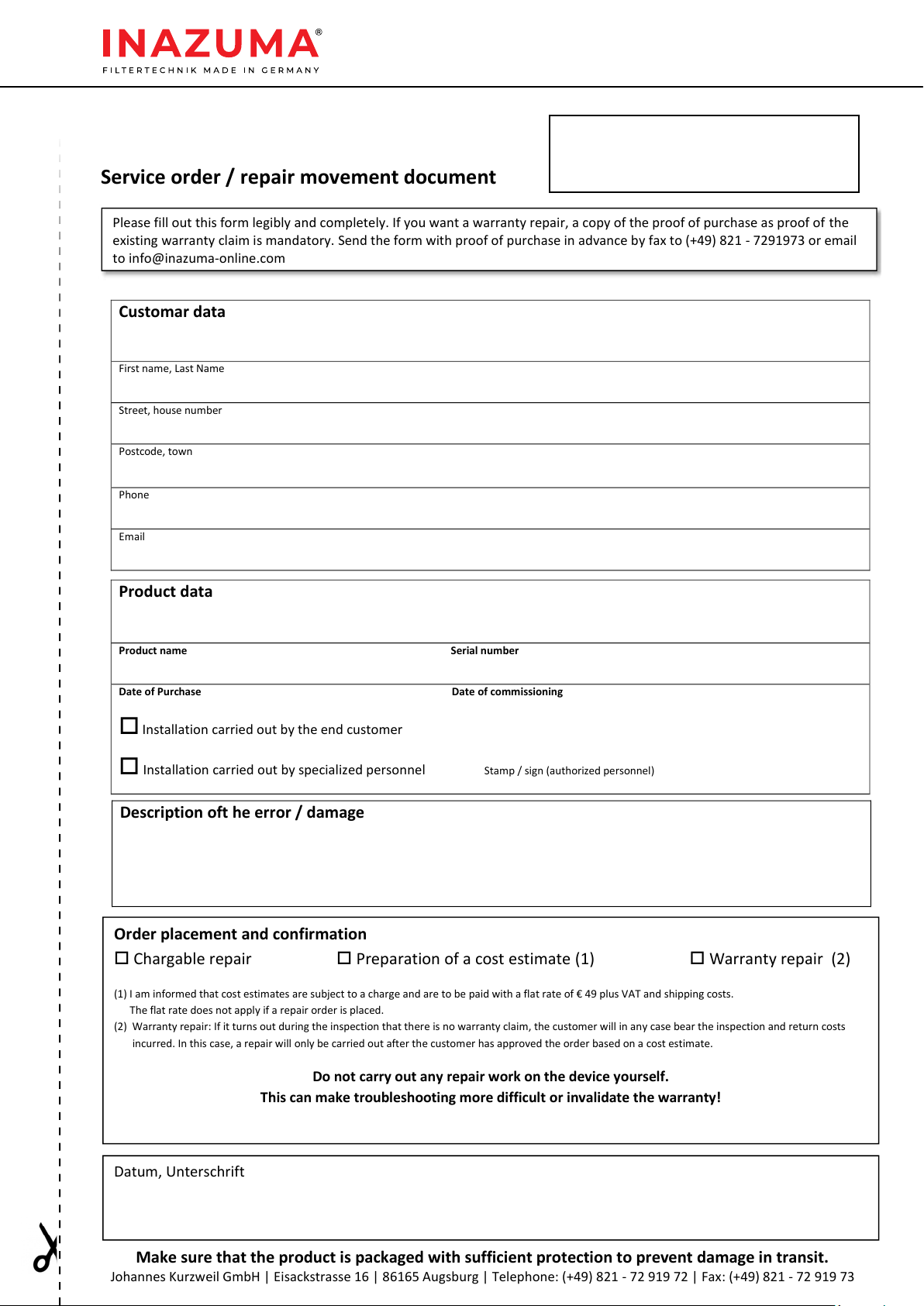
Service order / repair movement document
Please fill out this form legibly and completely. If you want a warranty repair, a copy of the proof of purchase as proof of the
existing warranty claim is mandatory. Send the form with proof of purchase in advance by fax to (+49) 821 - 7291973 or email
to info@inazuma-online.com
Customar data
First name, Last Name
Street, house number
Postcode, town
Phone
Email
Product data
Product name Serial number
Date of Purchase Date of commissioning
Installation carried out by the end customer
Installation carried out by specialized personnel Stamp / sign (authorized personnel)
Description oft he error / damage
Datum, Unterschrift
Order placement and confirmation
Chargable repair Preparation of a cost estimate (1) Warranty repair (2)
(1) I am informed that cost estimates are subject to a charge and are to be paid with a flat rate of € 49 plus VAT and shipping costs.
The flat rate does not apply if a repair order is placed.
(2) Warranty repair: If it turns out during the inspection that there is no warranty claim, the customer will in any case bear the inspection and return costs
incurred. In this case, a repair will only be carried out after the customer has approved the order based on a cost estimate.
Do not carry out any repair work on the device yourself.
This can make troubleshooting more difficult or invalidate the warranty!
Serial number

FILTER TECHNOLOGY MADE IN GERMANY
Inazuma®Drum Filters
Manufacturer:
Inazuma
Johannes Kurzweil GmbH
Eisackstraße 16
DE – 86165 Augsburg
Tel.: (+49) 821/ 72 91 97 2
Fax: (+49) 821 / 72 91 97 3
info @inazuma -online .com
www. inazuma-online .com
Technical modications and errors excepted
WEEE-Reg.-Nr. DE 19429673
Manual Version 2020-01
You will be amazed!
Edelstahl -Trommellter &High - End -Teichzubehör
This manual suits for next models
12
Table of contents
Popular Water Filtration System manuals by other brands


Sterling
Sterling IM Series Installation instructions & owner's manual

Intewa
Intewa SEPAMAT F 20 Installation and user manual

Schenker
Schenker SMART 80 Installation, use and maintenance manual

Whirlpool
Whirlpool WHELJ1 Installation and operation manual

GCTek
GCTek AlphaONE instructions

Veolia
Veolia Orion II 500 Operator's manual

DeWalt
DeWalt DXCM019-0352 quick start guide

Milli-Q
Milli-Q IQ Element user manual

Excalibur Water Systems
Excalibur Water Systems Sureflo SFLC Series Installation and user guide

Evince
Evince ELITE EV-ELT-948-1.0 owner's manual

Drop
Drop BX-20-201 operating instructions

AquaMaster
AquaMaster AMS700 Owner's manual and installation guide