Inbal Valves 700D Series Instruction manual

Model 799D
Automatic Water Control Valve
Series 700D
F02-01-02
General Description
The Inbal Automatic Water Control
Valve series 700D is a pressure operated,
sleeve actuated, axial valve, designed
from basic concepts, with a built-in
actuator to function as control valve in
fire protection system. The Inbal series
700D is used as deluge, preaction, dry
pipe, remote control, pressure reducing,
pressure relief, pump control, water level
control, and other types of control
valves. The standard material Inbal
Valve is rated to 300 psi (21 bar) and
requires a minimum line pressure of 20
psi (1.5 bar) for operation. Upon removal
of the control pressure the Inbal Valve
opens instantaneously, yet very
smoothly, to prevent any water hammer
in the piping system. The Inbal 700D
performance and ease of resetting are not
affected by vertical or horizontal
installation.
The Inbal Automatic Water Control
Valve utilizes the unique N.M.M.P. (No
Moving Mechanical Parts) design. The
only moving part when the Inbal Valve
operates, is the reinforced sleeve which
forms a drip-tight seal with the corrosion
resistant core. The Inbal design also
prevents false operation due to transient
surges in water supply pressure. The
N.M.M.P. design and variety of mater-
ials and coatings make the Inbal Auto-
matic Water Control Valve ideally
suitable for use with brackish or sea
water similar to those found in chemical
and petrochemical facilities or in
offshore platforms. It can also be used as
a foam concentrate control valve in
foam/water systems.
The Inbal Automatic Water Control
Valve series 700D is available in sizes
1½" (40 mm) to 12" (300 mm). The
valves have threaded, flanged, or wafer
inlet and outlet ends.
Technical Data
Approvals
The Inbal Automatic Water Control
Valve is FM approved to 300 psi (21 bar)
in sizes 3", 4", 6", and 8" (80, 100, 150,
and 200 mm). Consult the FM Approval
Guide for acceptable applications.
Inbal Deluge Valves have Lloyd's, DNV,
and ABS Type Approvals for all sizes and
most models.
Model Numbers
Inlet End Outlet End Model No.
Threaded Threaded 711D
Flanged Flanged 733D
Grooved Grooved 766D
Wafer Wafer 799D
Sizes
Threaded Ends:
1½", 2", 2½", & 3"(40, 50, 65, & 80 mm).
Flanged Ends:
2", 2½", 3", 4", 6", 8", 10", &12" (50, 65,
80, 100, 150, 200, 250, & 300 mm).
Wafer Ends:
3", 4", 6", 8", 10", & 12" (80, 100, 150,
200, 250, & 300 mm).
End Standards
Threaded End:
NPT or BSPT.
Flanged End:
ANSI B16.5 class 150 & 300 ;
ISO 7005 - PN10, 16 & 25 ;*
BS 10 Table D & E ;**
AS 2129 Table D & E ;**
Jis B 2212, 2213, 2214 ;**
Wafer End:
Fits all above standards.**
*Compatible with DIN 2501 and BS 4504.
** Exclude:
BS 10 Table E 6" (150 mm);
AS 2129 Table E 6" (150 mm);
Jis B2212 regular flange in sizes 4", 8", &12"
(100, 200, & 300 mm).
Grooved Ends:
2", 3", 4", 6", & 8", (50, 80, 100, 150, &
200 mm).
Grooved End:
ANSI/AWWA C606-87
F02-01-02-002
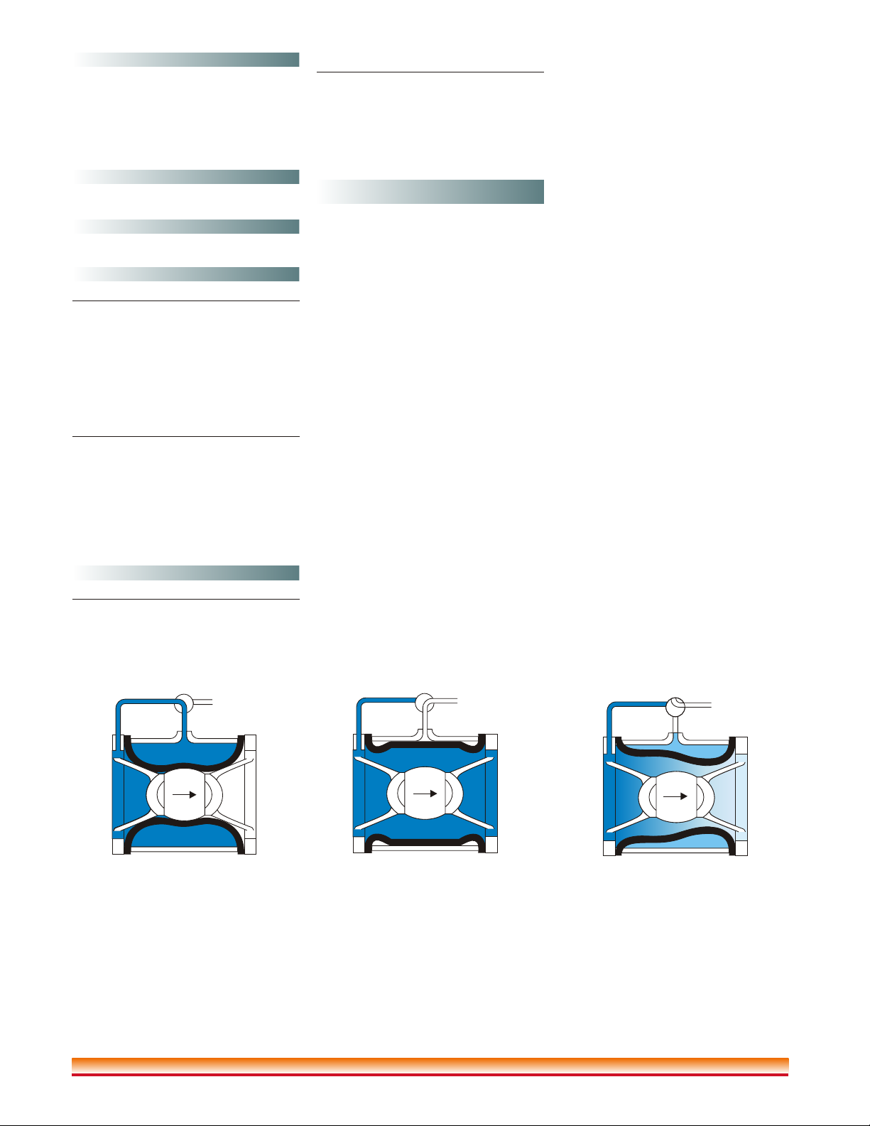
Full open operation
When pressure in the Control Chamber is
relieved to the atmosphere, the Inbal
Valve opens wide. The sleeve assembly
is safely enveloped by the housing.
Tight closing operation
When pressure from the valve inlet (or an
equivalent independent operating
pressure) is applied to the Control
Chamber, the Inbal Valve closes drip
tight. The fabric sleeve safely envelopes
the resilient sleeve giving full support.
Modulating action
A stable throttling position is obtained
when a quantity of pressurized fluid is
held in the Control Chamber. It is the
amount of fluid in the Control Chamber
that determines the position of the sleeve
assembly. The Control Chamber can be
alternately filled or exhausted to achieve
the desired operating condition.
Figure (1) Figure (2) Figure (3)
Pressure Rating
Maximum working pressure*: 300 psi
(21 bar). Minimum Working Pressure:
20 psi (1.5 bar).
*Standard material valve.
Temperature Range
oo
Water: Max. +150 F (+65 C).
Installation Position
Vertical or horizontal.
Materials
Standard
Valve Housing:
Carbon Steel (SAE 1021).
Valve Ends:
Ductile Iron (ASTM A536 65-45-12).
Sleeve:
SMR5 Elastomer reinforced with Poly-
ester and Kevlar.
Optional
Cast Steel ;
Bronze ;
NickelAluminium Bronze ;
Stainless Steel AISI 316 ;
SuperAustenitic Stainless Steel ;
Super Duplex Stainless Steel ;
Titanium.
Coating
Standard
Powder epoxy coated. Thickness: 0.004"
(0.1 mm) external and internal surfaces.
Optional
High built epoxy coated and polyure-
thane finish. Thickness: 0.01" (0.3 mm).
®
Halar coated. Thickness: 0.02"
(0.5 mm).
Halar ® is a registered trade mark of Ausimont USA Inc.
Features
!The Inbal Valve, designed for control
valve service from basic concepts,
utilizes a built-in sleeve actuator.
!No Moving Mechanical Parts
(N.M.M.P.) construction ensures a long
life of dependable operation, reducing
the cost of maintenance.
!The N.M.M.P. Design assures
frictionless operation. No sticking after
staying for prolonged periods in a
closed position. Suitable for brackish
and sea water.
!Quick, yet soft opening performance -
eliminates water hammer and conse-
quent damage.
!The line pressure or an equivalent
independent operating pressure, is
sufficient to close the Inbal Valve
tightly.
!Soft closure performance due to
inherent characteristics of the Inbal
Valve. Utilizes no spring to ensure
surge-free closing.
!Pressure rating of 300 psi (21 bar) for
standard materials valve due to rigid
construction.
!Suitable for vertical or horizontal
installation with no effect on Inbal
Valve performance.
!Lightweight - easy to be installed and
maintained.
!Available with threaded, flanged, and
wafer ends to various standards.
!Unique principle of operation prevents
false operations due to water surges.
!Wide range of sizes for an ideal system
design.
!Compact design - minimum space for
valve and trim. Enable installation in
confined spaces.
!Epoxy coating supplied as standard-
ensures excellent corrosion resistance.
!Variety of available materials - to
ensure corrosion-free service even
under severe conditions.
!Compatible with electric, pneumatic,
and/or hydraulic release.
!Excellent regulating performance in a
wide range of flows and line pressures.
!Wide selection of pilot valves,
actuators, and accessories to design the
ideal control valve for the purpose.
!A single Inbal Automatic Water
Control Valve can perform multi-
function controls.
!Every single valve is hydraulically
tested in real flow and pressure
conditions.
!Innovative design with a long record of
proven performance.
Operation
The Control Chamber of the Inbal
Automatic Water Control Valve is the
annular space between the valve
Housing and the Sleeve. The valve is
held in a closed position as long as inlet
pressure is maintained in the Control
Chamber.
In the set position, the water pressure is
transmitted from the upstream through
the valve trim to the Control Chamber,
and the Inbal Valve stays closed.
Actuation of the valve by a manual,
hydraulic, pneumatic, or electric release
system allows venting of the pressure in
the Inbal Valve Control Chamber, and
the valve opens wide, permitting a flow
of water to the piping system. When a
pressure or flow control is added, the
Control Chamber is monitored to
modulate a preset delivery pressure,
maximum inlet pressure, or flow rate.
The principle of operation is illustrated
in Figures (1) through (3). The nominal
pressure losses are shown in Graph (1).
Installation
Refer to the Trim Chart applicable to the
specific Inbal Valve model in use.
1. When the Inbal Valve is delivered,
carefully unpack and visually check
that there has been no damage to the
operating components, piping, and
fittings.
2. The Inbal Valve must be installed in
an area not subject to freezing
conditions.
3. Always flush the pipelines before
installing the valve.
4. Place the Inbal Valve in the piping in
the outlet of the Water Supply Valve.
Verify that the arrow on the valve
housing matches the actual flow
direction. The Inbal Valve may be
installed in any position. Determine
which side the valve will be accessed
from and locate all the components
accordingly.
5. Install the Inbal Valve in the piping
system. Refer also to the applicable
Installation Guide.
Threaded End Valve - connect the
female threaded ends of the Inbal
Valve to the male threads of the
piping. Use the pipe joint compound
sparingly on the male threads only.
Flanged End Valve - connect with
bolts and nuts, the valve flanges to
the existing flanges in the piping
system, using gaskets in between.
Complete bolting with uniform
tightening.
0
0
0
0
0
Wafer End Valve - Install the Inbal
Valve between the piping flanges.
Place gaskets between the valve ends
and the pipe flanges. Insert four of
o
the stud bolts, 90 apart around the
valve, through the bolt sleeves and
the pipe's flanges, and tighten with
nuts. Complete bolting with uniform
tightening.
6. Complete the trim assembly by
connecting the preassembled
sections, or assemble the trim if
ordered in loose component form.
Refer to the applicable Trim Chart
and Installation Guide.
7. The pressure supply to the trim must
always be sourced from either inlet
of Water Supply Valve or Inbal
Valve upstream, through a ½" pipe.
8. Exhaust tube must be free of any back
pressure. Provide an air gap between
the exhaust tube and drain facility.
9. Set the Inbal Valve by following the
applicable Resetting procedure.
10. Test the Inbal Valve, the trim, and
alarms according to the applicable
Testing procedure.
Resetting
The Inbal Automatic Water Control
Valve system must be reset and restored
to service as soon as possible after
automatic, emergency, or manual
actuation. Refer to the relevant bulletin
for detailed procedure.
0
0
0
0
F02-01-02-003
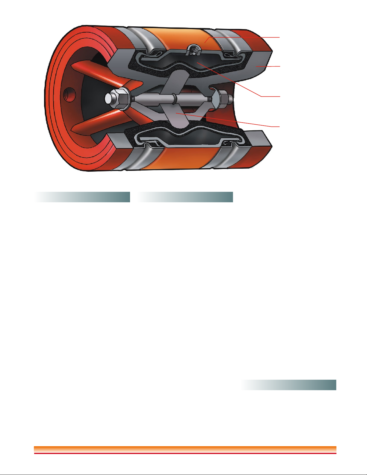
Core
Sleeve Assembly
Housing
End
January 2005 / F02-01-02
Automatic Water Control Valve
Series 700D
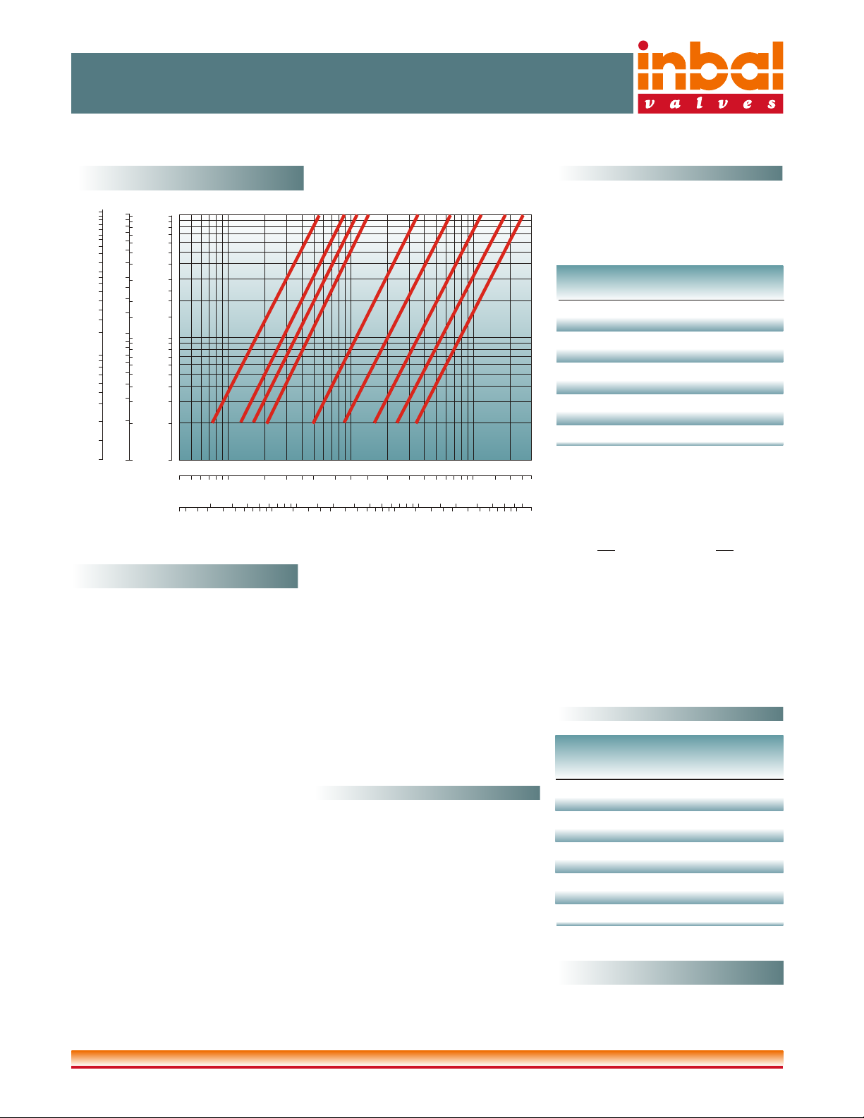
Flow Chart
Graph (1)
Flow Rate
45 6 710 20 30 40 50 75 100 200 300 500 1000150 2000 3000
2345 10 15 20 30 40 50 100 150 200 300
500
700
20 30 40 50 100 200 1000
2000
3000
5000 10000
300
500
6"
4"
3"
2"
1½” 12"
300
10"
250
8"
200150100805040
inch
mm
l/s
gpm
3
m/h
bar
0.10.98
0.2
0.3
0.4
0.5
3
10.1
0.01
0.02
0.03
0.04
0.05
1.5
2
2
3
4
5
10
10
15
20
30
40
50
100
5
4
0.15
0.2
0.3
0.4
0.5
1
psi
0.14
0.3
0.4
0.2
0.5
1
KPa m H O
2Inbal Valve Size
Head Loss
15
10
3
1.5
2
5
4Valve Size Flow Factor
mm inch Kv Cv
40 1½'' 60 70
50 2'' 90 105
65 2½" 115 133
80 3'' 140 162
100 4'' 330 383
150 6'' 610 708
200 8'' 1150 1334
250 10'' 1630 1891
300 12'' 2365 2743
Flow Factor
Q Flow rate in
=
3
m /h.
Kv = Flow factor.
Use Table (1)
Q
Kv
( )
2
DP =
DP = Head loss
i n b a r .
Table (1)
Table (2)
Valve Size Displacement
U.S.
mm inch liter gallon
40 1½" 0.3 0.08
50 2" 0.3 0.08
65 2½" 0.3 0.08
80 3" 0.3 0.08
100 4" 0.5 0.13
150 6" 1.7 0.45
200 8" 3.5 0.92
250 10" 8.1 2.1
300 12" 12.7 3.4
Control Chamber Displacement
To define the head loss through an Inbal
valve at a specific flow rate use the
following equation (for water only):
The Flow Factor Cv (Kv) is defined as
3
the flow rate in gpm (m /h) of liquid at
00
68 F (20 c), flowing at 1 psi (1bar) head
loss.
Q Flow rate in
=
gpm.
Cv = Flow factor.
Q
Cv
( )
2
DP =
DP = Head loss
in psi.
Trim Testing and/or Control Testing, as
well as a Quarterly Testing as listed in the
applicable data sheet of the specific
application in which the Inbal Auto-
matic Water Control Valve participates.
An Annual Testing shall include Trip
Testing, Semi-Annual Testing, and
Quarterly Testing as listed in the appli-
cable data sheet of the specific appli-
cation in which the Inbal Automatic
Water Control Valve participates.
Removal
To remove the Inbal Valve:
1.Close all the pressure supply valves:
a) Water Supply Valve
b) Trim Shutoff Valve.
2.Open the Emergency Release Valve to
release the water pressure from the
Inbal Valve Control Chamber.
3.Open the drain valves to allow all the
water to drain.
4.Remove the trim from the Inbal Valve.
5.Remove the Inbal Valve from the line
for inspection.
6.To reinstall, follow the Installation
procedure section (use new gaskets for
flanged or wafer valve).
Inquiries/Orders
The Data Sheet For Inquiries/Orders
(bulletin F01-05-XX) should be
submitted.
Maintenance, Inspection,& Testing
It is recommended that periodic
inspections and tests be conducted by
qualified personnel to ensure that the
Inbal Automatic Water Control Valve
and related equipment are in good
operating condition. The inspection and
testing activities should be done
according to NFPA Standards, the
guidelines and regulations of the
authorities having jurisdiction, and the
following instructions. It is recom-
mended that the Inbal Valve be tested,
operated, cleaned, and inspected on a
routine basis.
AWeekly Visual Inspection shall include
Water Supply Valve position, free
pressure access, and major trim compo-
nents as listed in the applicable data sheet
of the specific application in which the
Inbal Automatic Water Control Valve
participates.
AQuarterly Testing shall include Alarm
Testing, Strainer Cleaning, and major
components testing as listed in the
applicable data sheet of the specific
application in which the Inbal Auto-
matic Water Control Valve participates.
ASemi-Annual Testing shall include
2½"
65
Inbal Valves UK Ltd. 53 Limes Road, Tettenhall, Wolverhampton, W. Midlands, WV6 8RD England, Tel +44-1902-561111 Fax +44-1902-561113, E-mail: inbal @ inbalvl.com
This manual suits for next models
4
Other Inbal Valves Control Unit manuals


Popular Control Unit manuals by other brands


Littfinski Daten Technik
Littfinski Daten Technik RS-16-O-B Assembly instruction

Graco
Graco Gun Flush Box 570046 Instructions-parts list

ASA Hydraulik
ASA Hydraulik SDA Series manual

Automationdirect.com
Automationdirect.com HX-ECOM Series manual

Supermicro
Supermicro SBA-7121M-T1 user manual

Bosch
Bosch KTS 5a Series Original instructions


