Inbal Valves 700D Series User manual
Deluge Valve, Hydraulic Actuation
Series 700D/DG/DX - 04/14A 01 Local Resetting
Model 799DG-04A01
Mil Ltd F03-02-01
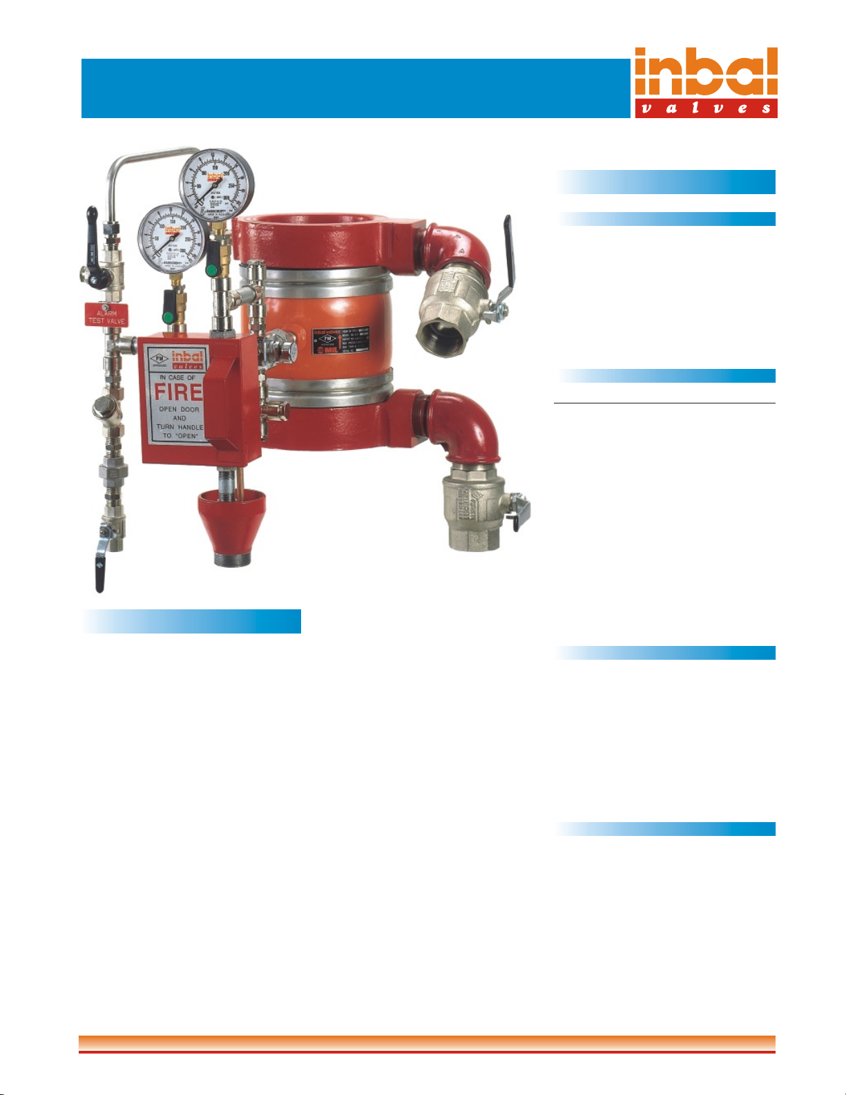
GeneralDescription
The Inbal Deluge Valve with Hydraulic
Actuation Trim is specifically designed
for fire protection systems actuated by a
fire detection and release system of wet
pilot sprinklers and/or hydraulic manual
control. The Inbal Automatic Water
Control Valve, which is used in this
deluge system, is a pressure operated,
sleeve actuated, axial valve designed for
useinfireprotectionsystems.
The Inbal Hydraulically actuated
Deluge Valve is used for automatic or
manual operation. The wet pilot line
functions as a thermal detector equipped
with a fixed temperature release. When
one or more of the sprinkler heads,
located on the pilot line, fuses, or when a
manualreleasestationisoperatedlocally
or remotely, the Inbal Deluge Valve
opens and water flows from all open
sprinklers and/or nozzles on the system.
As soon as the releasing system and the
sprinkler piping are reset, the Inbal
DelugeValve resetting ismerely done by
activatingtheresetknob.
The control trim includes all the pilot
valves, accessories, fittings, and gauges
to provide for proper operation in either
vertical or horizontal installation. The
standard material Inbal Deluge Valve is
rated to 300 psi (21 bar) and is available
in sizes 1½" (40 mm) to 12" (300 mm).
The valves have threaded, flanged,
grooved,orwaferinletandoutlet ends.
The only moving part in the Inbal
Deluge Valve, when it operates, is the
reinforced sleeve, which forms a drip-
tight seal with the corrosion resistant
core. It has a smooth opening to prevent
anywaterhammerinthepipingsystem.
The unique design and variety of
materials and coatings make the Inbal
Deluge Valve ideally suitable for use in
brackish or sea water, similar to those
found in chemical and petrochemical
facilities or in offshore platforms. The
Inbal can also be used as a foam
concentrate control valve in foam/water
systems.
TechnicalData
Approvals
The Inbal Hydraulically Controlled
Deluge Valve series 700DG-04A is FM
approved to 300 psi (21 bar) in sizes 3",
4", 6", and 8" (80, 100, 150, and 200
mm). Consult the FM Approval Guide
for acceptable applications. Inbal
Deluge Valves have Lloyd's, DNV, and
ABS TypeApprovalsforallsizes.
Model Numbers
Inlet End Outlet End Model no.
Threaded Threaded 711DG-04A01
Threaded Grooved 716DG-04A01
Flanged Flanged 733DG-04A01
Flanged Grooved 736DG-04A01
Grooved Grooved 766DG-04A01
Wafer Wafer 799DG-04A01
"DG" can be replaced with "D" or "DX" depends
on the Inbal Automatic Water Control Valve series
in use. See bulletins F02-01-01, F02-02-01, and
F02-03-01.
The above model numbers refer to fully trimmed
valves. For basic trim, replace "04" with "14".
(See also bulletin F01-03-01 for control trims "24"
&"34").Forexample: 711DG-14A01is athreaded
ends deluge valve with basic, hydraulically
actuatedtrim.
Sizes
ThreadedEnd:
1½", 2", 2½", & 3" (40, 50, 65, & 80mm).
FlangedandGroovedEnds:
1½", 2", 2½", 3", 4", 6", 8", 10", & 12"
(40, 50, 65, 80, 100,150, 200, 250, &
300mm).
WaferEnd:
3", 4", 6", 8", 10", & 12" (80, 100, 150,
200,250,&300mm).
End Standards
ThreadedEnd:
NPTorBSPT.
FlangedEnd:
ANSI B16.5class150 &300;
ISO7005- PN10,16 &25;
BS 10 Table D&E;
AS 2129 Table D&E;
Jis B 2212, 2213,2214.
WaferEnd:
Fitsmostoftheabovestandards.
GroovedEnd:
ANSI/AWWAC606-87.

F03-02-01-002
PressureRating
Maximum working pressure*: 300 psi
(21bar).
*standardmaterialvalve.
Temperature Range
00
Water: Max. +150F (+65 C).
Installation Position
Vertical or horizontal.
Materials
Standard
ValveHousing:
ForgedSteel(SAE1021).
Valve EndsandWafer FlowTest&Drain
Ends:
DuctileIron(ASTMA536 65-45-12).
Threaded, Flanged, and Grooved Flow
Test&Drain Ends:
CarbonSteel (SAE1020).
Sleeve:
SMR5 Elastomer reinforced with poly-
esterandKevlar.
ControlTrim:
Brass Nickel Chrome plated, Stainless
Steel,andGalvanizedSteel.
Optional
Cast Steel ;
Bronze ;
Nickel Aluminium Bronze ;
Stainless Steel AISI 316 ;
Super Austenitic Stainless Steel ;
Super Duplex Stainless Steel ;
Titanium.
Coating
Standard
Powderepoxy coated.Thickness:0.004"
(0.1mm)externalandinternalsurfaces.
Optional
High built epoxy coated and polyure-
thanefinish.Thickness:0.01"(0.3mm).
®
Halar coated. Thickness: 0.02"
(0.5mm).
®
Halar is a registered trademark of AusimontUSA Inc.
ControlTrim
On standard, the control trim is supplied
preassembled in sections. If self
assembly is required, all the trim
components are supplied in loose form.
The complete control trim includes the
followingcomponents:
!FlowReleasePilot(F.R.P.)withabuilt-
incheckvalve.
!Y-Strainerwithastainlesssteelscreen.
!Alarm Test Valve - 3 way, L-port,
quarter turn ballvalve.
!Trim Shutoff Valve, Flow Test Valve,
and Drain Valve are quarter turn ball
valves.
!Supply and System Pressure Gauges,
withdualscale(psiandbar).
!PressureGaugeValves- 3 way,quarter
turnball valves.
!DrainCupandDrainTubes.
!AutomaticDrainValves.
!EmergencyReleaseStation.
Features
!No Moving Mechanical Parts
(N.M.M.P.) construction ensures a long
life of dependable operation, reducing
thecostofmaintenance.
!Quick, yet soft opening performance -
eliminates water hammer and conse-
quentdamages.
!The line pressure is sufficient to close
the Inbal Valve tightly. Can perform
also, when water supply valve is not in
use.
!Optional opening and/or closing speed
controlisavailable.
!Anticolumning device is available for
longorhighelevationwetpilotline.
!Fast and easy reset by thumb activated
knob.
!Supplied as standard preassembled in
sections- saves the self assemblycost.
!Remoteemergency releasestationscan
beusedformanualoperation.
!Can be installed vertically or
horizontally.
!Compact design - minimum space for
valve and trim.
!Unique principle of operation prevents
falseoperationduetowatersurges.
!Pressure rating to 300 psi (21 bar) for
standardmaterial valve.
!Wide range of sizes for an ideal system
design.
!Control trim made of high grade
materialsasstandard.
!Epoxy coating supplied as standard -
ensuresexcellentcorrosionresistance.
!Variety of available materials - to
ensure corrosion-free service even
under severe conditions.
!Thesame basictrimis compatiblewith
electric, pneumatic, and/or hydraulic
release.
!Additional functions, such as pressure
control or another release system,
couldbeaddedonthesamevalve body.
Operation
The Control Chamber of the Inbal
Automatic Water Control Valve is the
annular space between the valve
Housing and the Sleeve. The valve is
held in a closed position as long as inlet
pressure is maintained in the Control
Chamber.
The wet pilot line, equipped with closed
sprinkler heads, is pressurized through
the valve trim and located over the
protected area. The wet pilot line serves
thedualpurposeofthermaldetectionand
releasesystem.
In the set position, water pressure is
applied to the Control Chamber of the
Inbal DelugeValve and to the hydraulic
release system from the upstream of the
Water Supply Valve. Consequently, the
Inbal DelugeValvestaysclosed.
The Inbal Deluge Valve opens wide
when one or more of the sprinklers
installed on the wet pilot line fuses and
water pressure is allowed to vent, or
when a hydraulic manual release opens.
Either one of these operations releases
water from the Inbal Control Chamber.
The Inbal Deluge Valve opens fully
introducing a flow of water to the system
while activating the system alarm
devices. Water will flow from any open
sprinklers and/or spray nozzles on the
system. The operation of the Inbal
Deluge Valve and the flow released from
the Control Chamber activate the Flow
Release Pilot (F.R.P) to latch in an open
position, isolating the Control Chamber
from the inlet water supply. The F.R.P
operation prevents the Inbal Deluge
Valve from closing even if the open
releasing wet pilot line closes. The Inbal
Valve will close only when the Resetting
procedureisfollowed.
The maximum elevations in which the
wet pilot sprinklers or manual release
stations can be installed are shown on
Graph (1).They are presented in relation
tothe various lengths ofpilotlines and to
thewatersupplypressure.
The Emergency Release Valve is used
for emergency actuation of the Inbal
DelugeValveand for routine testing.
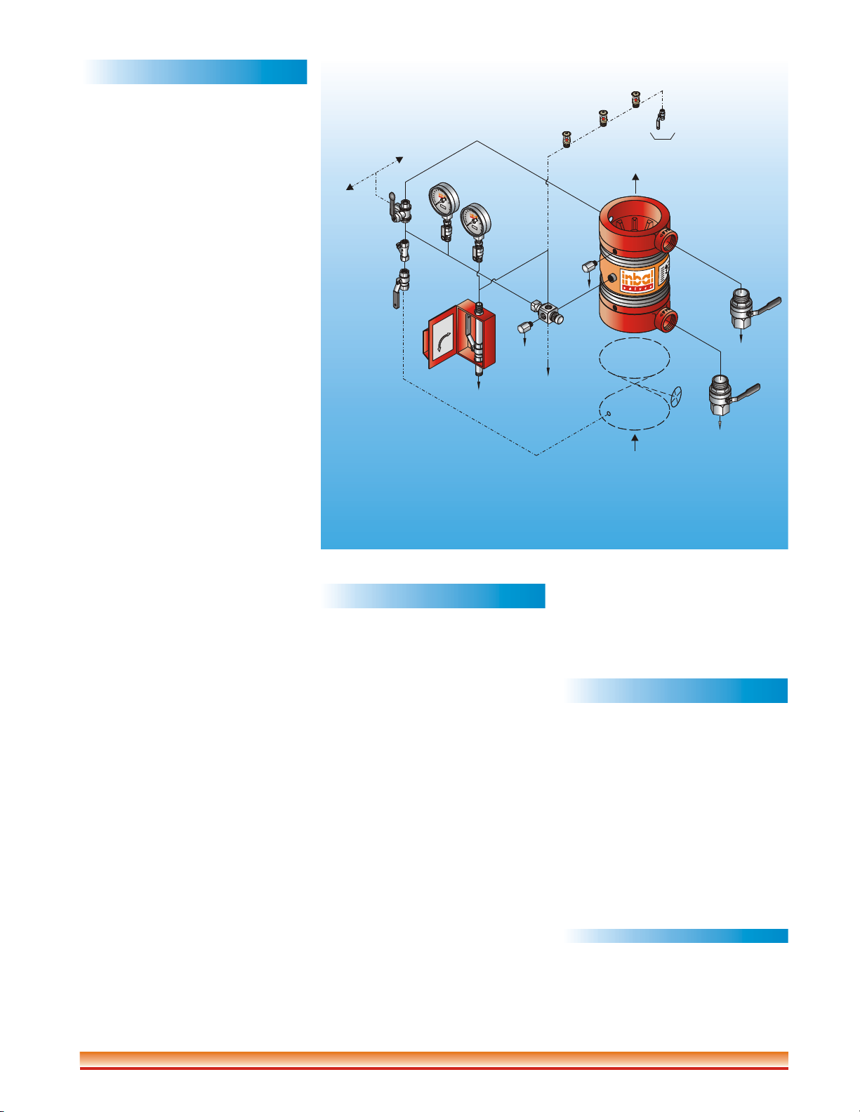
F03-02-01-003
7a Supply Pressure Gauge
7b System Pressure Gauge
17 Alarm Test Valve
18a Flow Test Valve
18b Drain Valve
_
SchematicControl Diagram 700DG-04A01
50
100
300
0
50
100
300
0
2
18a
5
6
17 7b
3
4
18b
1
4
To Drain
To optional release
systems (hydraulic,
electric, or pneumatic)
To System
To Drain
To Drain
Drain
To Drain
Wet Pilot Line
To
To Alarm
Pressure
Switch
To Water
Motor
Alarm
OPEN
CLOSE
EMERGENCY
MANUALVALVE
Inspector's
Test Valve
Water
Supply
Valve
7a
1Inbal Automatic Water Control Valve
2 Emergency Release Station
3 Flow Release Pilot (F.R.P.)
4 Automatic Drain Valves
5 Trim Shutoff Valve
6 Y-Strainer
Installation
Refer to the Trim Chart applicable to the
specific Inbal Deluge Valve model in
use.
1.When the Inbal Deluge Valve is
delivered, carefully unpack and visu-
ally check that there has been no
damageto the operatingcomponents,
piping,andfittings.
2.Always flush the pipelines before
installingtheInbalValve.
3.Place the Inbal Valve in the piping at
the outlet of the Water Supply Valve.
Verify that the arrow on the valve
Housing matches the actual flow
direction. Determine which side the
system will be accessed from and
locate the Inbal Deluge Valve
accordingly.
.Install the Inbal Deluge Valve in the
pipeline. Use gaskets, bolts, stud
bolts, bolt sleeves, and nuts as
required bythe valve ends.
.Complete the trim assembly by
connecting the preassembled
sections, or assemble the trim if
ordered in loose component form.
Refer to the applicable Trim Chart
andInstallationGuide.
.The water pressure supply to the
control trim must always be sourced
from the inlet of the Water Supply
Valvethrougha½"pipe.
.Connect the wet pilot line to the Flow
Release Pilot (F.R.P.). Refer to Graph
(1) which shows the maximum
elevations above the Deluge Valve at
which the release line (pilot sprink-
lers or manual release) should be
installed. An Anticolumning Device
is required when the release line
elevation exceeds the figure corres-
ponding to the minimum water
supply system pressure in which the
Inbal Deluge Valve is planned to
perform.
.It is recommended to install an inspe-
ctor's test valve on the hydraulic
release system. The inspector's test
valve is a locked closed ball valve
with an outlet end orifice equivalent
tothesmallestorificeofthereleasing
device provided on the system. The
inspector's test valve may be used to
verify adequate operation of the
deluge system when a releasing
deviceoperates.
9.Set the Inbal Deluge Valve by
followingtheResettingprocedure.
10.TesttheInbalValve,thetrim,andthe
alarms according to the Testing
procedure.
0
0
0
0
0
0
0
0
0
4
5
6
7
8
Resetting
The Inbal Deluge Valve system must be
reset and restored to service as soon as
possible after automatic, emergency, or
manualactuation.
Theprocedureisasfollows:
1.Close the Water Supply Valve. Water
flowalarmsarereset.
2.ClosetheTrimShutoff Valve.
3.Open the Flow Test Valve and Drain
Valve,allowingallthewatertodrain.
4.Inspect and replace any portion of the
detection system subjected to fire
conditions.
5.Inspect the trim and alarm Y-
Strainers.Clean if necessary.
6.Verify that the Emergency Release
Valveisinaclosedposition.
7.Open the Trim Shutoff Valve. Push
and hold the reset knob on the F.R.P.
and allow water pressure to build up
in the trim and in the Inbal Valve
Control Chamber. Wait and verify
that the pressure readings on both
pressuregaugesareequal.
8.Release the reset knob on the Flow
ReleasePilot(F.R.P).
9.Close theFlowTest Valve.
0
0
0
0
0
0
0
0
0
10.Fully open the Water Supply Valve.
Verify that there is no flow from the
Drain Valve, downstream of the
Inbal Valve.
11.Closethe DrainValve.
Maintenance,Inspection,&Testing
It is recommended that periodic inspec-
tions and tests be conducted by qualified
personnel to ensure that the Inbal
Deluge Valve and related equipment are
in good operating condition. The
inspection and testing activities should
be done according to NFPA Standards,
the guidelines and regulations of the
authorities having jurisdiction, and the
following instructions. It is recom-
mended that the Deluge Valve be tested,
operated, cleaned, and inspected at least
onaroutinebasis.
Inspection
Aweekly Inspection is recommended:
1.Verify that the Water Supply Valve is
sealedinfullyopen position.
2. Verify that the required water
pressure is being applied to the Inbal
DelugeValveinlet and trim.

Mil Ltd.17 Moshe Beker Street, P.O.Box 15200, Rishon Lezion 75051, Israel. Tel: +972 3 966 4350, Fax: +972 3 966 4320, E-mail:inbalvl@ attglobal.net
March 2000 / F03-02-01
300 psi
120 140 160 180
WATER SUPPLY SYSTEM PRESSURE
821 bar
9 10 11 12
820 ft (250 m)
1475 ft (450 m)
660ft (200 m)
Up to575 ft(175 m)
990 ft (300 m)
1650 ft (500 m)
1310 ft (400 m)
1150 ft (350 m)
Based on ½'' (15 mm) Schedule 40 pipe
280
If the maximum elevation of hydraulic release piping exceeds the limits
shown on the graph, use anticolumning device model 395-08 (see bulletin F40-14-01).
Deluge Valve, Hydraulic Actuation
Series 700D/DG/DX - 04/14A01
20
MAX. ELEVATION OF WET PILOT LINE
m H O
2ft HO
2
0
10
20
30
40
0
30
60
90
120
150
604020 80 100
5
23467
Pilot Line
Equivalent
Length
Wet Pilot Line - Design Data
3.Close the Alarm Test Valve. All local
alarms should stop sounding and
pressureswitchisreset.
4.Verify that the supply piping to the
alarmdrainsproperly.
DelugeTrimTesting
Asemi-annual Deluge Trim Testing
is recommended. Testing of the control
trim is conducted with no flow of water
tothesystem.
1.Open the Flow Test Valve to flush
away debris or foreign particles
which may have accumulated in the
Inbal Deluge Valve inlet.
2.Close the Flow Test Valve.
3.Close the Water Supply Valve
installed in the inlet of the Inbal
DelugeValve.
4.Open the inspector's test valve in the
hydraulic release system. Water
should be drained from the deluge
trim. Verify that the pressure reading
on the System Pressure Gauge drops
to zero which simulates an open
positionoftheInbalDelugeValve.
5.Reset the valve by performing the
instructionsinResetting.
Trip Testing
AnannualTripTestingisrecommended.
Performing the Trip Testing will cause
water to flow from all open sprinklers
and/or nozzles. Prevent damage by
takingnecessaryprecautions.
1.Open the Flow Test Valve to flush
away any debris or foreign particles
which may have accumulated in the
Inbal Deluge Valve inlet.
2.Close the FlowTest Valve.
3.TriptheInbalValvetoopenbyeither:
a)Openingtheinspector’stestvalve.
b) Opening the Emergency Release
Valve.
The water in the Inbal Valve Control
Chamber is released to the atmos-
phere. The Inbal Deluge Valve will
open wide and water will flow to the
system. All the water flow alarms
should operate. Verify that the whole
systemisworkingproperly.
4.Close the inspector's test valve or the
EmergencyReleaseValve.
5.Reset the valve by performing the
instructionsinResetting.
Removal
ToremovetheInbalDelugeValve:
1.Closeallthepressuresupplies:
a) WaterSupplyValve.
b) TrimShutoff Valve.
2.Openthe EmergencyReleaseValveto
release the water pressure from the
InbalValveControlChamber.
3.Open the Flow Test Valve and Drain
Valvetoallowallthewatertodrain.
4.Disconnect the union and remove the
trimfromthevalve.
5. Remove the InbalValve from the line
forinspection.
6.To reinstall, follow the Installation
procedure (use new gaskets for
flangedor wafer valve).
Inquiries/Orders
The Data Sheet For Inquiries/Orders
(bulletin F01-05-01) should be
submitted.
Graph (1)
3.Verify that the Trim Shutoff Valve,
AlarmTest Valve,EmergencyRelease
Valve, Pressure Gauge Valves, Flow
TestValve,andDrainValve are in set
position.
4.The Supply and System Pressure
Gauges should be checked for
accuracy.
5.Visually inspect for broken or
missing parts, or other evidence
of impairedprotection.
StrainerCleaning
A quarterly Strainer Cleaning is
recommended:
1.Closethe TrimShutoffValve.
2. Remove the covers of the trim and
alarmY-Strainers.Cleanif necessary.
3.OpentheTrimShutoff Valve .
AlarmTesting
A quarterly Alarm Testing is
recommended:
1.Test the Water MotorAlarm or Alarm
Pressure Switch by opening the Alarm
TestValve.
2.Water Motor Alarm should be audible.
Alarm Pressure Switch should
activate.
This manual suits for next models
6
Other Inbal Valves Control Unit manuals


Popular Control Unit manuals by other brands

Sophos
Sophos SG 105wSG 105XG 105wXG 105SG 115SG 115wXG 115XG 115wSG 125SG 125wXG 125XG 125wSG 135SG 135wXG 135XG... Mounting instructions

Aaeon
Aaeon COM-TGUC6 user manual

Simatek
Simatek GFCD 16 manual

BENDIX
BENDIX TC-4 MODULATING CONTROL VALVE manual

HIMA
HIMA HIMax X-DO 12 51 manual

Wheelock
Wheelock ZC-3 installation instructions


Siemens
Siemens SINUMERIK 805 operating instructions

Toshiba
Toshiba nv Series instruction manual

infiniDome
infiniDome GPSdome 1.01 installation manual

Quectel
Quectel EG91 Series Hardware design

Telit Wireless Solutions
Telit Wireless Solutions GainSpan GS2K Series Hardware user's guide

Berker
Berker 751616 Series Technical documentation