Incra Twin Linear User manual
OWNER’S MANUAL
Please read this Ownerʼs Manual before
use and keep it at hand for reference.
NOTE
If you are setting up the TWIN at your
table saw, follow the mounting instructions
included with the TSII Base Mount Kit
6
-1
1
0
2
3
4
5
11
13
14
15
16
17
18
19
12
10
6
0
2
3
4
5
1
9
11
12
13
14
15
16
10
8
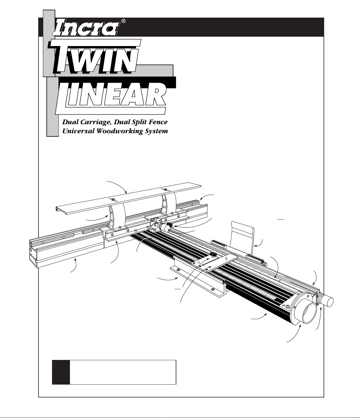
Hi-Rise fence cap
Infeed carriage
(black)
Carriage clamp
Outfeed fence
Red
micro adjust
knob
Dust
collection
port
Rear black thumbscrew (Tighten only
during outfeed fence offset adjustments)
Fence cap braces
Stainless steel
primary scale
Black infeed fence
adjustment knob
Infeed fence
Forward black thumbscrew (Loosen only during fence
offset adjustments
Outfeed carriage
(gold)
Lexan®“floating” scale
Hairline cursor
Fence mounting
bracket
Base
Please take just a few minutes of your time to read
your new INCRA TWIN LINEAR ownerʼs manual.
Youʼll find it full of interesting and useful information
about safety, setting up, and putting to use the many
wonderful features of the TWIN. And itʼs all written
by someone who continues to use every INCRA
product from the very first INCRA Jig all the way up
to our best offering ever — the INCRA TWIN LINEAR!
In eight years of using one INCRA Jig or another
virtually every weekend (and some week nights) Iʼve
come to know these tools inside out. In writing this
manual I want to share this experience with you. Iʼve
attempted to make everything as clear as possible,
but if you are in doubt, weʼll be here to help. See
you in the shop!
—
Perry

SAFETY
. . . . . . . . . . . . . . . . . . . . . . . . 2
TWIN LINEAR SETUP
Accessories . . . . . . . . . . . . . . . . . . . . . . . . . . . . . . . 5
Hi-Rise
™
Fence Cap . . . . . . . . . . . . . . . . . . . . . 5
Installing the Extender Bar . . . . . . . . . . . . . . . . . 6
Extender Bar and Stop . . . . . . . . . . . . . . . . . . . . 6
Incra Stop Assembly . . . . . . . . . . . . . . . . . . . . . 6
OPERATION
Moving to a New Scale Setting . . . . . . . . . . . . . . . . 8
Micro Adjusting . . . . . . . . . . . . . . . . . . . . . . . . . . . . 9
Offset Adjustment . . . . . . . . . . . . . . . . . . . . . . . . . 10
Infeed Fence Adjustment . . . . . . . . . . . . . . . . . 10
Outfeed Fence Adjustment . . . . . . . . . . . . . . . . 11
Gap Adjustment . . . . . . . . . . . . . . . . . . . . . . . . . . . 12
Zero Clearance Subfence . . . . . . . . . . . . . . . . . . . . 12
IN-LINE FENCE APPLICATIONS
General Purpose Router Fence . . . . . . . . . . . . . . . .14
Vertical Panel Raising . . . . . . . . . . . . . . . . . . . . . . 15
Joint Making . . . . . . . . . . . . . . . . . . . . . . . . . . . . . 15
OFFSET FENCE APPLICATIONS
Jointing . . . . . . . . . . . . . . . . . . . . . . . . . . . . . . . 16
Shaping . . . . . . . . . . . . . . . . . . . . . . . . . . . . . . . 17
ADJUSTMENTS
Adjusting the Clamping Pressure . . . . . . . . . . . . . . 18
Realigning Carriage and Fence Racks . . . . . . . . . . 19
Realigning Infeed and Outfeed Fences . . . . . . . . . . 19
Parts and Optional Accessories . . . . . . . . . . . . . . . 20
SAFETY
2
Important safety instructions for using the INCRA
TWIN LINEAR. Before using, read and follow all of the
instructions and safety information in this manual.
❐When using the INCRA TWIN LINEAR in conjunction
with any other tool, first read and follow all instructions
and safety information in that toolʼs ownerʼs manual.
❐Always turn off the power and wait until the bit or blade
comes to a complete stop before changing the setting of
any part of the INCRA TWIN LINEAR or INCRA Stop.
❐Always keep both hands behind the fence when moving
the INCRA TWIN LINEAR to a new setting.
❐Before making a cut, always make sure that the
carriage clamp is fully engaged and the jig is securely
locked in place.
❐When using the INCRA TWIN LINEAR with other
tools, make sure that all safety guards and other
safety equipment supplied by the manufacturer of that
tool are securely in place and functional. Never let
the INCRA TWIN LINEAR interfere with another toolʼs
safety equipment.
❐Use appropriate safety devices. Keep hands clear of the
bit or blade. Always use a push stick, rubber soled push
block, or other safety device to keep your hands safely
away from the cutting tool.
❐Wear safety glasses, hearing protection, and follow all
normal shop safety practices.
❐DO NOT modify the INCRA TWIN LINEAR in an attempt
to use it with non-INCRA accessories.
❐When adjusting the fence opening, never position the
infeed or outfeed fence ends closer than 1/8” from the
router bit.
❐After making adjustments to the fence opening, be sure
to tighten the four socket head cap screws that secure
the fences to the fence mounting brackets.
❐After making any offset adjustments to the fence, always
tighten the carriage tie (black clamping knob behind the
outfeed fence mounting bracket) and pull the carriage
clamp up into the locked position.
❐When using fence settings in which the router bit is
partially recessed in the fence opening, always insure
that the bit is centered within the opening.
❐Never let the router bit come into contact with any part
of the INCRA TWIN LINEAR, INCRA Stop, or INCRA
Right Angle Fixture.
❐When using large diameter vertical or horizontal panel
raising bits or any other large diameter bit, always
follow that router bit manufacturerʼs operation and
safety recommendations.
❐Whenever it is necessary to remove large amounts of
stock, always use multiple side-by-side passes to
achieve the final cut. Several shallow cuts are safer and
will yield better results.
CONTENTS

For those of you setting up the TWIN on an “INCRA
TWIN ready” router table, the mounting holes will be
predrilled with T-nuts installed. Skip to Step 2.
Suggested Router Table Dimensions
If you donʼt already own a router table, Fig. 1 gives minimum
dimensions for a table top designed around the TWIN and its
capabilities. If you have a router table top that is not long
enough to handle the full range of the TWIN, see the Tip at
right for an easy way to extend your table dimensions.
Drill Mounting Holes
Begin by drilling the (8) mounting holes in your router
table top. A paper pattern is provided to make locating the
holes easy. Draw a line extending from the center of the
hole in your router table toward the far edge of the table,
Fig. 2. This line needs to be parallel to the edges of the
table so take a few measurements at each end of the line to
make sure it is. Position the dark line on the pattern right on
top of the line you draw. Slide the pattern back until the
marked edge is 22" from the center of the hole in your table.
Tape the pattern in place.
3
Extending your router table length
Screw aluminum or steel angle to underside of
router table to provide support for table extension.
The extension needs to be flush and parallel to the
table top. Shim to alignment as necessary.
Fig. 1
Suggested router
table dimensions
Fig. 2
Drill mounting holes
NOTE
1
TWIN LINEAR SETUP
Extension wing
Wood screws
Aluminum or steel angle
Paper pattern
Drill 1⁄4" holes if you want to use the 10-24 x 13⁄4" machine
screws and hex nuts.
Drill 1⁄8" holes if you want to use the 10 x 7⁄8" wood screws.
NOTE
Placing the pattern 22" away from the center of the
hole will allow you the maximum usable range of the
TWIN. Moving the pattern closer to the hole on
smaller tables does not limit the full use of the many
features of the TWIN, it only decreases the distance
that the fence can be moved from the cutter later on.
The base mount hardware pack gives you a couple of
fastener options. You can mount the base with (8) 10 x 7⁄8"
wood screws with washers, in which case youʼll want to
predrill the (8) holes with a 1⁄8" drill bit. Or you can use the
(8) 10-24 x 1 3⁄4" phillips pan head machine screws and
predrill the (8) holes with a 1⁄4" bit. I prefer the machine
screws, but if you choose this option, make sure you have
clearance under the table for the washers and nuts at all eight
mounting hole locations.
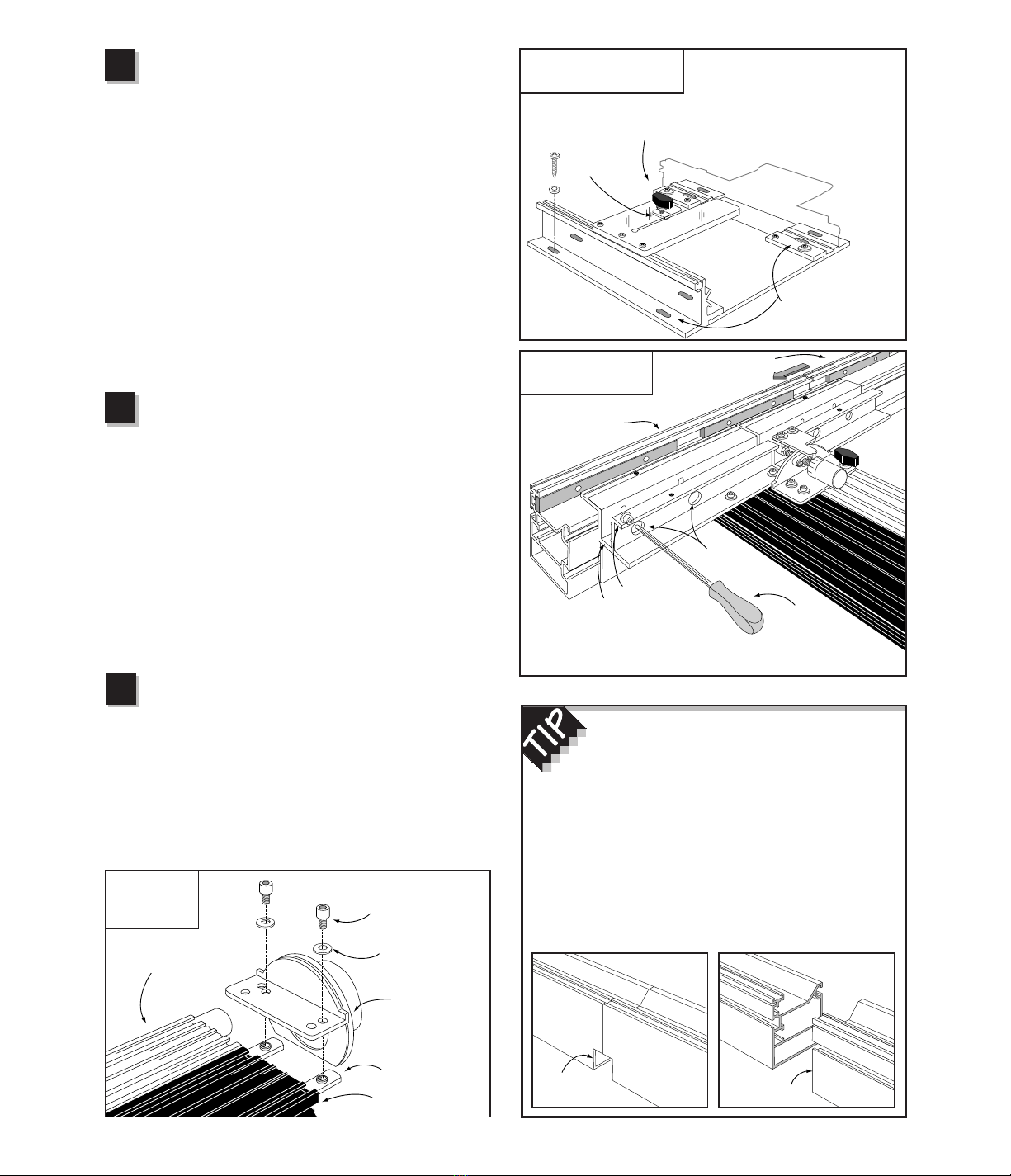
Attach Base to Router Table
Slide the carriage out of the base. Depending on which
fastener option you selected in Step 1, attach the TWINʼs base
to your router table. Put a washer on the screw first and make
sure you place a screw in each of the eight slotted holes in the
base, Fig. 3. on the next page. If you are using the machine
screws, place a washer and hex nut on the screw from under
the router table. Tighten all (8) mounting screws.
24"
12" 12"
43"
31"
Existing router
table top
22"
2
FACT Infeed and Outfeed
Infeed refers to everything that is before the cutter,
while outfeed is everything that is after the cutter. Youʼll
hear about infeed and outfeed fences, of course, but
you also have an infeed and outfeed side to your router
table, and youʼll learn how to set an infeed or outfeed
stop later in this manual. Your INCRA TWIN LINEAR is
the only fence of its kind to offer separate infeed (black)
and outfeed (gold) carriages, each controlling its own
fence. The “twin” carriages can operate in tandem, or
independently for offset fence applications.
4
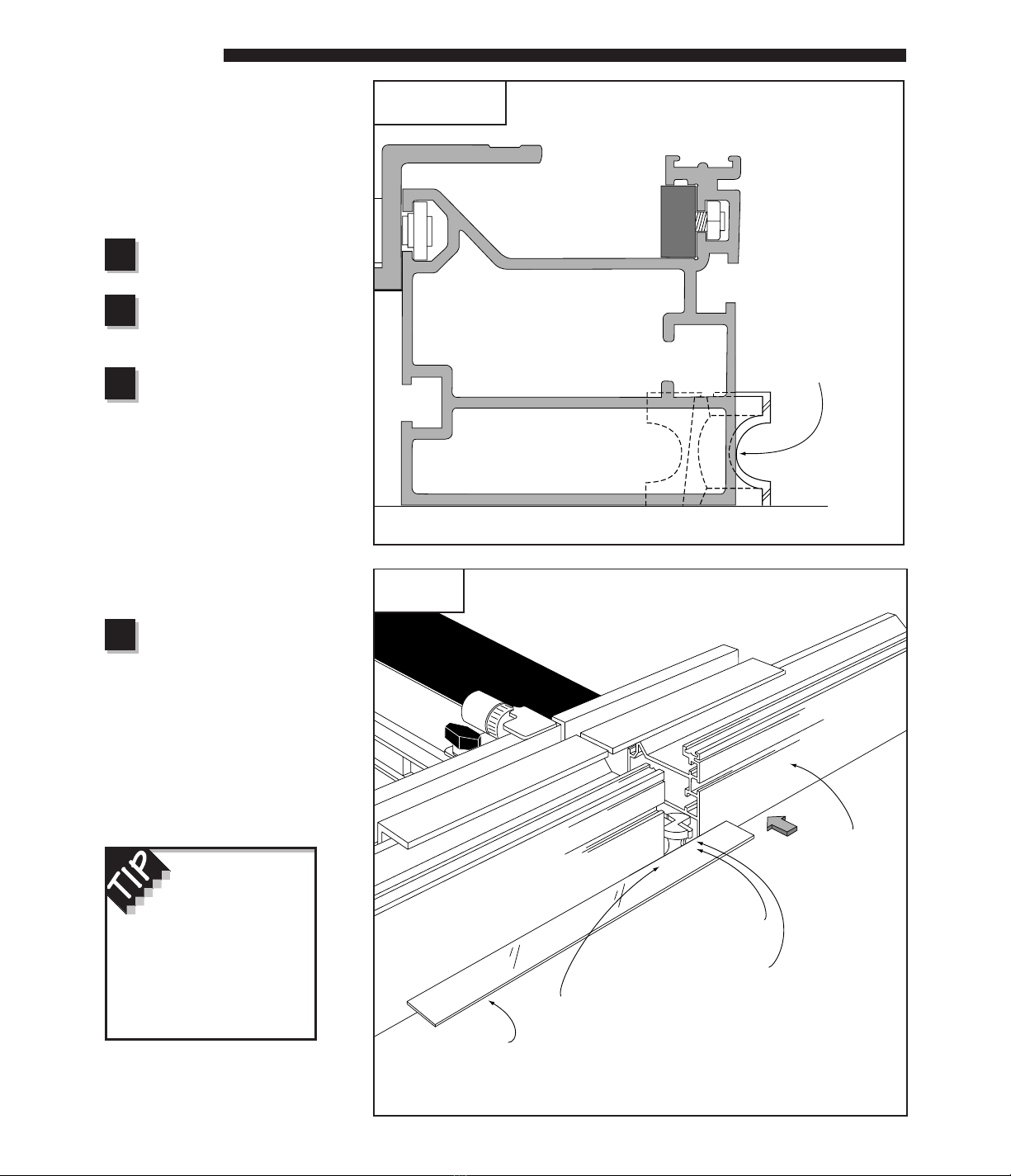
Attach Outfeed Fence
Before you slide the carriage back into the base, take
a look at the black thumbscrew that passes through the clear
acrylic hairline cursor on the base. Fig. 3. The thumbscrew
is screwed into a rectangular nut. Make sure that the
rectangular nut slides into the T-slot in the top of the infeed
carriage when you slide the carriage back into the base.
Now slide the carriage into the base and position the front of
the fence directly over the hole in your table top. Pull the
carriage clamp handle up into the locked position.
Using the supplied hex head tool, loosen the (4) socket head
cap screws about a half a turn through the access holes in
the rear of the fence mounting bracket. See Fig. 4. Place the
remaining fence half end-to-end with the half already
mounted and slide them both (as though they were one
continuous fence) until the notch at the front of the fence is
aligned directly over the hole in your router table. Retighten
the (4) socket head screws.
Initial Alignment for Primary Scale
With the carriage clamp locked in place, slide the
primary (stainless steel) scale to position the nearest scale
mark directly under the hairline cursor. The scale is held in
place by a magnetic strip. Lifting one end of the scale off of
the magnet will decrease the tension, allowing the scale to
slide more easily. Slide the Lexan plastic scale to position
the nearest scale mark under the cursor as well. You will
change the scale positions the first time you install a bit or
blade and “zero” to the cutter, but remember this: Since the
INCRA TWIN will only clamp every 1⁄32", you must always
make sure the carriage clamp is locked before positioning
any of the scales or joinery templates. If the clamp is
unlocked when the scales are positioned, it almost
guarantees inaccurate cut placement.
Install Dust Collection Port
Place washers on (2) 1⁄4-20 X 3⁄8" socket head cap
screws and place them through the holes as shown in Fig. 5.
Loosely attach (2) 1⁄4-20 rectangular nuts, then slide the nuts
into the T-slots on the top of the infeed (black) carriage. Slide
the port assembly forward until it stops, then tighten the
fasteners. Should you ever want to remove the carriage from
the base again, you must first remove the port by loosening
these same fasteners. The dust collection port accepts a
21⁄2" diameter hose.
Fig. 3
Attach base to router table Place mounting screw with washer
through each of the eight slotted holes
in the base. If using machine screws,
secure with washers and nuts from
beneath the table.
Fig. 4
Attach outfeed fence
Take a look at the TWINʼs fence. At one end
of each fence half youʼll find a flat cut, while on
the other end youʼll notice a small notch. Place the
two notched ends together whenever you want a
continuous fence surface above the cut area. Youʼll find
this especially useful when using the Right Angle
Fixture for joinery, since it tracks along the top surface
of the fence. Placing the two flat cut ends together is
perfect when you want to open or close the gap
between the fences for large or small diameter cutters.
4
5
Fig. 5
Install dust
collection port
3
Note: Mounting holes
are shaded in
illustration for clarity
Black
thumbscrew
Rectangular
nut
Socket head
cap screw
Fence mounting
bracket Hex tool
Access
holes
Infeed fence
Outfeed fence
Loosen (4) socket head cap screws that secure infeed fence and slide
outfeed fence onto fence mounting bracket. Retighten mounting screws.
Notched end Flat cut end
1/4– 20 x 3/8"
socket head cap screws
Stainless steel
washer
1/4– 20
rectangular nuts
Outfeed carriage
Infeed carriage
Port assembly

ACCESSORIES
Hi-Rise Fence Cap
Locate the (2) fence cap braces over
the threaded holes on top of the
fence mounting bracket and attach
with the 1⁄4-20 x 3⁄8" socket head
cap screws and washers from the
Hi-Rise hardware packet. Using the
(2) 10-32 x 1⁄2" phillips pan head
screws, nylon washers, and 10-32
hex nuts, attach the fence cap to the
two braces as shown in Fig. 6. The
slotted holes in the fence cap should
be aligned to provide access to the
front brace mounting screws. Use a
straightedge to align the leading
edge of the fence cap with the front
face of the infeed and outfeed fences
and tighten the two cap mounting
screws, Fig. 7. Though designed for
permanent residence on your INCRA
TWIN, you may prefer to take it off,
since it is not needed for most of the
things youʼll do with the TWIN. Just
remove the (4) socket head cap
screws and store the Hi-Rise
assembly for future use. Place the
fasteners back in the threaded holes
and tighten.
5
Fig. 6
Attach Hi-Rise fence cap
Fig. 7
Align fence cap with fence
The fence and Hi-Rise
fence cap provide the
low and high support
necessary for large
vertical panel work. If
you want to add an
auxiliary fence to
bridge the gap between
the two, use the drill
and counterbore
dimensions shown in
the illustration. Use
1⁄4– 20 x 3⁄4" machine
screws with washers
and hex nuts to attach
the auxiliary fence.
Hi-Rise fence cap
1/4– 20 x 3/8"
socket head cap screws
Nylon washer
Fence cap braces
10 – 32 hex nut
Stainless steel washer
Fence mounting
bracket
Threaded holes
Hi-Rise
fence cap
Straightedge
Fence
First: Place
straightedge
against fence
Second: Loosen screws
and slide fence cap to
straightedge. Retighten
screws.
Hi-Rise
fence cap
1/4– 20 x 3/4"
machine screw
Hex nut
captured in
T-slot
Fence
9/16" dia. x 3/8" deep counterbore
5/16" dia. through hole
7 15/32"
1 31/32"
10 – 32 x 1/2"
phillips pan head screw
Installing Extender Bar
Hereʼs another accessory youʼll find
useful from time to time. The extender
bar will allow you to set its sliding stop
up to 16" beyond the end of either the
infeed or outfeed fence. Fig. 8 shows
the proper placement for the extender
bar. Insert the extender bar with the
scale facing forward and lock in place
with the 1⁄4-20 X 3⁄8" socket head
cap screw, stainless steel washer, and
rectangular nut as shown.
A second stop extender bar can be
purchased should you want to
increase the stop range beyond both
ends of your fence.
Extender Bar and Stop
Position the extender bar about 2"
beyond the fence end and using the
supplied 1⁄4"-20 X 1⁄2" nylon
thumbscrew, attach the extender bar
stop. See Fig 9. The stop can be
used on either end of the extender bar
to increase your stop range beyond
the ends of the fence. When not is
use, the stop can be turned around
and locked to the extender bar. This
storage position places the stop out of
the way, leaving the front face of the
fence uninterrupted for through cut
operations.
CAUTION: Never allow the
opposite end of the extender bar
to protrude into the cut area.
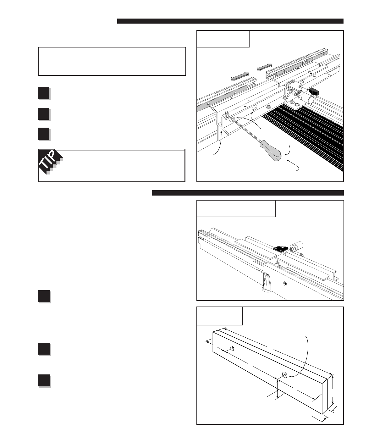
Incra Stop Assembly
Using the (2) 8-32 x 3/8" phillips
pan head screws and 8-32 hex
nuts, fasten the 4" long blue
INCRA rack to the INCRA Stop
and tighten the screws. Slide the
3/4" x 5" plastic strip into the slot
in the stop and secure with two
1/4"-20 x 1/2" nylon thumbscrews.
Thread the (2) 3/8"-16 x 1/2" nylon
thumbscrews into the INCRA
Stop. Fig.10. One or both of
these thumbscrews can be used
to clamp the INCRA Stop to the
fence. In use, the plastic strip
provides a non-metallic stop
surface which can be shaped for
special stop setups and can be
micro adjusted by loosening the
smaller thumbscrews.
6
Fig. 9
Attach extender bar stop
Fig. 10
Assemble INCRA Stop #8 – 32 x 3/8" phillips pan
head screws
1/4– 20 x 1/2"
nylon thumbscrews
3/8– 16 x 1/2"
nylon
thumbscrews
Plastic stop strip
INCRA rack
#8 – 32 hex nut
Fig. 8
Extender bar installation
1/4– 20 x 3/8"
socket head cap screw
Rectangular
nut
Stainless
steel washer
1/4– 20 x 1/2"
nylon thumbscrew
Extender bar stop
05
6
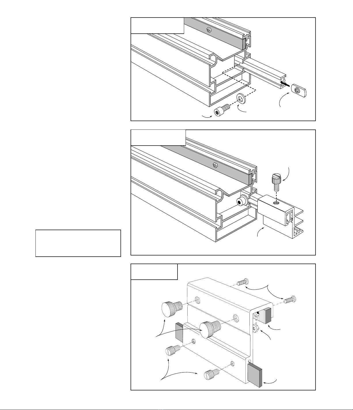
Zeroing INCRA Stop to the End of a Board
For most applications, you will be using your INCRA Stop on
the outfeed end of the INCRA Fence to control the length of a
cut relative to the front end of the board. Here is how to set
the initial scale position for this type of setup:
After installing the bit you wish to use, set the fence to
bit distance at about 1". Place a square cut piece of
scrap stock against the fence with the end of the board
against the infeed side of the bit. Turn the bit to find
the high spot.
Next, lock the INCRA Stop to the fence on the outfeed
side of the bit with the plastic stop strip as close as
possible to the end of the board. Adjust the position of
the stop strip until both the strip and the bit contact the
end of the board. Fig. 11.
You now have the choice of setting the sliding scale to
one of three initial positions:
In most cases, you will simply slide the scale to align
the 0" mark on the scale with the end of the INCRA
Stop nearest the bit. When set to this initial position,
the scale reading at any subsequent INCRA Stop
location will give you a direct readout of the total
length of the cut. (See Dimension “A”, Fig. 12.)
If you wish the subsequent scale readings to reflect
the distance from the front end of the board to the
center of the cut (Dimension “B”, Fig. 12), slide the
scale to an initial reading under the end of the INCRA
Stop equal to minus one half of the bit diameter.
Example:
If you are using a 1⁄2" diameter bit,
complete Steps 1 and 2 above then slide the scale to
read negative 1⁄4".
If you want the scale reading for future INCRA Stop
positions to reflect the distance between the end of
the board and the outfeed edge of the cutter
(Dimension “C”, Fig. 12), then slide the scale to an
initial reading equal to minus the bit diameter.
IMPORTANT: Some stop setups may require that some
portion of the fence scale be slid from the outfeed fence into
the infeed fence or visa versa. DO NOT offset the fence halves
with a scale in this position, as it may damage the scale.
7
Slide scale to 0" for a direct readout of Dimension “A”
Slide scale to “minus 1/2of the bit diameter” for a
direct readout of Dimension “B”
Slide scale to “minus diameter of the bit” for a direct
readout of Dimension “C”
C
Fig. 12
Initial scale
setting
Fig. 13
Dual stop
operations
B
A
Fig. 11
Top view of stop setup
First:
Slide the board up to contact
the “high spot” on the bit
Second:
Lock the INCRA
Stop to the fence
and adjust the
position of the
plastic stop strip
to contact the
end of the board
Third:
Slide the scale to read one of
the initial scale settings as
described in Fig. 12 below
INCRA
Stop
1
2
3
Dual INCRA Stop Operations
Using the same setup process described above and a
second INCRA Stop, you will find the precise positioning
of mortises on a board quite simple. The
INCRA Jig
Projects and Techniques Book
covers this technique fully
and includes several unique projects which feature dual
INCRA Stop operations. See Fig. 13.
A
B
A
C
A

6
-1
1
0
2
3
4
5
11
13
14
15
16
17
18
19
12
10
6
0
2
3
4
5
1
9
11
12
13
14
15
16
10
8
Fig. 14
Moving to any new scale setting
First:
Unlock carriage clamp
Second:
Slide fence as you view scale
through hairline cursor
Third:
Return clamp to
upright “locked”
position
OPERATION
8
Moving to a New
Scale Setting
Moving the fence to any new scale
setting is just as easy as moving any
other fence youʼve used before. Push
the carriage clamp down to unlock the
carriage, then slide the fence as you
sight through the hairline cursor.
When you see your measurement
under the hairline, pull the clamp back
up to the locked position, Fig. 14.
Remember that the INCRA TWIN will
only clamp every 1/32", so donʼt try to
clamp in between scale marks. It just
wonʼt work!
Although the clamping
pressure has been factory
adjusted, you may wish to
fine-tune the pressure to suit
your individual needs. If so, use
the thin plastic shims provided
and follow the instructions
shown on page 18.
CAUTION: For your safety, keep
your hands behind the fence
when moving to any new scale
position.
For more information on using
INCRA tools on the router table,
table saw and drill press,
pick up the
INCRA JIG Projects
and Techniques
, available from
you local INCRA dealer. This
148 page book contains detailed
plans with over 400 illustrations
and photos to build 14 of
Perry McDanielʼs intriguing
original projects.

Micro Adjusting
The micro adjust feature of your
INCRA TWIN allows for precise
positioning of the fence to any
location between the 1/32" tooth
spacing of the INCRA sawtoothed
racks. Youʼll find this feature
extremely handy the next time you
need to widen a mortise by a hair
for a great fitting mortise and tenon
joint. Use the micro adjuster for a
flawless fit when cutting grooves to
accept inlay strips or to loosen up a
tight-fitting box joint cut with an
undersized bit. Youʼll find it
especially useful for setup
operations like “zeroing” or
“centering”. Hereʼs a step-by-step
look at operating your INCRA
TWINʼs micro adjuster. See Fig. 15
as you follow the steps.
Pivot flip clip into
position under
carriage clamp
Micro adjustments are always made
with the carriage clamp halfway
between clamped and unclamped.
The spring-loaded flip clip will hold
the carriage clamp in this half-
clamped micro adjust mode position.
Use your right hand to quickly pivot it
in or out as necessary.
Unlock the carriage clamp
With the flip clip in place, the carriage clamp will
automatically spring to the micro adjust mode.
Micro adjust the fence position
Rotate the knob with the red dial located at the rear
end of the outfeed (gold) carriage. Turn the micro adjust
knob clockwise to move the fence toward the cutter, or
counterclockwise to move the fence away from the cutter.
Lock the carriage clamp
Pull the carriage clamp up to lock the carriage in
place, then pivot the flip clip back to its original position.
Gauging the distance moved when micro adjusting is easy.
A full turn of the knob equals 1/32" of movement, a half turn
equals 1/64". For smaller adjustments, the red dial is marked
in 1/1000" increments. After micro adjusting you can re-zero
the dial to the pointer by rotating the dial (not the knob) with
your fingers. See Fig. 16.
The micro adjust feature of the INCRA TWIN has an
adjustment range of +1/4" from mid-range. The range scale
decal on the carriage shows how much range remains in
either direction. To read the scale, just sight along the end of
the gold bar that overlaps the decal. Fig. 16.
9
NOTE
Do not continue to turn the micro adjust knob counterclockwise beyond the
minus
1
⁄
4
" range shown on the decal. If the knob is unscrewed beyond this
point, factory reinstallation may be required.
To avoid running out of micro adjustment
range in the middle of a project, you want to
remember two things: First, always micro adjust
back to mid-range before beginning a new project.
Second, whenever you need to micro adjust a
distance greater than 1⁄32", use the INCRA positioning
racks to get as close as possible before reaching for
the micro adjust knob.
6
0
Range
Scale
2
30
28
26
4
0
28
26
30
2
6
4
Fig. 16
Micro-adjust scale
Use the scale on the red dial
to accurately gauge the
distance moved. After micro
adjusting, dial can be
rotated to read zero
Gold bar Pointer
Range scale
0
30
2
Fig. 15
Micro adjusting
First:
Pivot flip clip into
position under
carriage clamp
Second:
Unlock carriage clamp Third:
Turn micro adjust knob
Fourth:
Lock carriage clamp
and return flip clip to
original position
Flip clip
Red micro
adjust
knob
2
3
4
1

Offset Adjustment
The infeed and outfeed fences of your INCRA TWIN
can be moved independently in two directions to
provide a variety of setup configurations. By making
the offset adjustments described below, you can
position the fences “in-line” for standard cutting
operations such as grooving, rabbeting, and joint-
making. You can “offset” the infeed and outfeed fences
for specialty cutting applications such as shaping or
jointing an edge.
Infeed Fence Adjustment
Though the INCRA TWIN design provides for both infeed
and outfeed fence adjustments, the infeed fence adjustment
is by far the more important of the two. In fact, all offset
fence operations can be set by adjusting only the infeed
fence and, since it is the easier of the two adjustments, this
is the adjustment you should memorize. See Fig. 17 as
you read through the steps.
Pivot flip clip into micro adjust position
Unlock the carriage clamp
With the flip clip in place, the carriage clamp will
automatically spring to the micro adjust mode.
Loosen the forward black thumbscrew
The thumbscrew is located at the forward end of the
outfeed (gold) carriage. It serves as a lock between the
infeed and outfeed carriages and must always be loosened
to make an offset adjustment. Loosen the thumbscrew
about 1/2turn.
Tighten the forward black thumbscrew
Tighten the thumbscrew loosened in Step 3. This
locks the infeed and outfeed carriages together.
Lock the carriage clamp back in place
Pull the carriage clamp up to lock the carriage in
place, then pivot the flip clip back to its original position.
Fig. 17
Infeed fence adjustment
Micro adjust the infeed fence position
Rotate the knob with the black dial (located at
the forward end of the carriage Turn the knob clockwise
to move the infeed fence backward. Once again, the
knob is calibrated so that one full turn equals 1/32" of
movement, 1/2turn equals 1/64" and, for smaller
adjustments, the knob is marked in 1/1000" increments.
To move the infeed fence forward, rotate the knob
counterclockwise as you pull forward on the infeed
fence. The infeed fence will not move forward by simply
turning the knob. You must pull the fence forward as the
knob is turned.
10
FACT:
Rotating the knob with
the black dial micro
adjusts the infeed (black)
carriage and its attached
fence, not the outfeed
fence. Because the knob
is located behind the
outfeed fence, it may
seem like the outfeed
fence is moving, but itʼs
not. Just remember
this: The knob with the
black dial adjusts the
fence with the black
carriage. Black dial,
black carriage.
Knob with black dial
adjusts black carriage
First:
Pivot flip clip
under carriage
clamp
Second:
Unlock carriage clamp
Third:
Loosen black thumbscrew 1⁄2turn
Fourth:
Turn knob with black dial
Fifth:
Retighten thumbscrew
Sixth:
Lock carriage clamp
2
3
4
1
When attaching an infeed zero clearance
subfence as described on page 12, you will
move the infeed fence backward as much as 3/4".
Instead of turning the micro adjust knob, simply
slide the fence backward the necessary distance.
5
6
Forward black
thumbscrew
Infeed fence

Tighten the forward black thumbscrew
Tighten the thumbscrew located at the forward end
of the outfeed gold carriage. This locks the infeed and
outfeed carriages together.
Lock the carriage clamp in place
Pull the carriage clamp up to lock the carriage in
place and pivot the flip clip back to its original position.
Loosen the rear black thumbscrew next
to the hairline cursor.
11
Outfeed Fence Adjustment
Most offset fence operations can be accomplished with an
infeed fence adjustment, but on occasion you may wish to
fine-tune the outfeed fence without altering the infeed
fence position. Hereʼs how it is done. See Fig. 18 as you
read the steps.
Tighten the rear black thumbscrew
Itʼs located next to the hairline cursor. This
thumbscrew locks the position of the infeed carriage.
Place carriage clamp in micro adjust
mode and loosen forward black
thumbscrew
Pivot the flip clip under the carriage clamp and unlock the
clamp. Now loosen the black thumbscrew located at the
forward end of the outfeed (gold) carriage.
Micro adjust the outfeed fence position
Set the red dial on the micro adjust knob located at
the rear end of the outfeed (gold) carriage to read zero.
Rotate the knob clockwise to move the outfeed fence
forward. If you find it necessary to micro adjust the fence
backward from the original zero scale reading you must
rotate both micro adjust knobs (black and red)
counterclockwise by the same amount.
2
3
4
1
Fig. 18
Outfeed fence adjustment
First:
Tighten rear black thumbscrew
Second:
Place carriage clamp in micro
adjust mode and loosen forward
black thumbscrew
Third:
Turn knob with
red dial
Fourth:
Tighten forward black thumbscrew
Fifth:
Lock carriage clamp
Sixth:
Loosen rear black thumbscrew
5
6
Rear black thumbscrew
Forward black
thumbscrew
Zero Clearance Subfence
The large fence offset range offered by the TWINʼS dual
carriage design provides an interesting approach to the use
of zero clearance subfences. Typically a zero clearance
subfence is a long piece of wood with the profile of a
particular router bit band sawn into the face. When attached
to the router table fence and moved into position the router
bit nestles into the cutout. This close fit around the router bit
provides both additional support and tearout protection for
the boards to be cut. By offsetting the TWINʼS infeed fence
an amount equal to the thickness of the subfence you can
quickly produce an infeed only subfence that offers perfect
tearout control and infeed support. Hereʼs how:
Prepare subfence blank
Begin with a smooth flat piece of wood 3/4" thick x 3"
wide x 16" long. I prefer medium density fiberboard. Itʼs
inexpensive and usually pretty flat. I donʼt recommend
plywood because it splinters too easily. Drill and
counterbore the subfence using the dimensions shown in
Fig. 21.
Adjust th fence gap
Install the cutter in your router and set the fence gap.
(see Gap Adjustment section above) so that the fence ends
are no closer than 1/8" from the cutter.
Offset infeed fence
Move the fence away from the cutter and offset the
infeed fence about 3/4" behind the outfeed fence (Fig. 22) on
the next page. Note: An infeed offset of 3/4" will move the
black adjustment knob beyond its working range, so instead of
turning the knob as described in Step 4 on page 10, just slide
the infeed carriage back by hand.
Gap Adjustment
Follow these steps to adjust the opening between the
infeed and outfeed fences (See Fig. 19)
Caution: When adjusting the fence opening or
gap, never position the aluminum fence ends
closer than 1/8” from the router bit.
Using the supplied hex tool, loosen the
(4) socket head cap screws that hold the
fences to the fence mounting bracket.
Open or close the fence gap by sliding
each fence to the desired position
Tighten the fence mounting screws
12
2
3
1
See Tip on page 4 for fence mounting
options to consider when adjusting the gap
in the fence.
Fig. 19
Adjusting the fence gap
First:
Loosen (4) socket head cap
screws through access holes
in fence mounting bracket
Second:
Adjust gap
Third:
Tighten fence mounting screws
Fig. 20
Zero clearance subfence on infeed fence
2
3
1
Fig. 21
Subfence dimensions
4" 16"
8"
4" 3"
1 31/32"
3/4"
Hex tool
Access holes
Fence
mounting
bracket
5/16" through hole with
3/4" dia. x 3/8"deep
counterbore
13
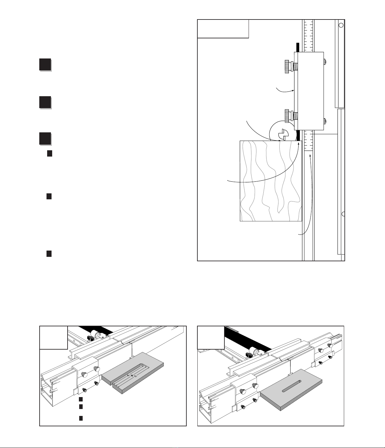
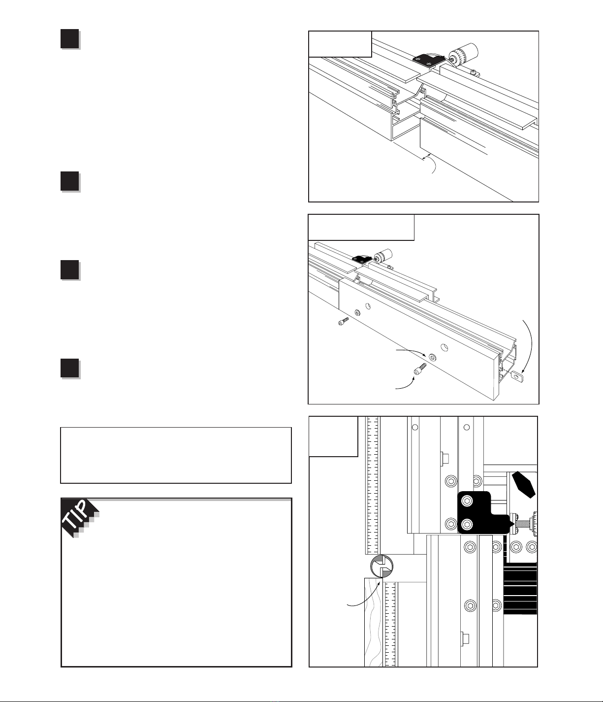
Attach subfence to infeed fence
Place the (2) 1/4- 20 x 3/4" socket head cap screws
with washers through the holes in the subfence and loosely
attach the 1/4- 20 rectangular nuts. (Fasteners supplied in
the auxiliary fence hardware pack) Slide the subfence onto
the infeed fence so the fasteners are captured in the T-slots.
Move the subfence forward until stopped by the outfeed
fence and tighten the fasteners, Fig. 23. Now fine-tune the
fence offset so that the subfence is flush with the outfeed
fence. Always make sure to tighten the black thumbscrew
that ties the two carriages together after making any offset
adjustment.
Position fence for initial profiling cut
Loosen the mounting screws that secure the
subfence about 1/2turn and slide the subfence back away
from the outfeed fence. Move the TWINʼS fence up to the
cutter and position it so the rear face of the subfence is in
line with the approximate center of the cutter. See
overhead view, Fig. 24.
Make the profiling cuts
Turn on the router and using a good rubber soled push
block advance the subfence forward into the cut. When the
subfence touches the outfeed fence, back the subfence out of
the cut and turn off the router. Unlock the carriage clamp and
move the Twinʼs fence back about 1/8". Relock the clamp,
then repeat the cut. Continue this process until you have cut
completely through the subfence.
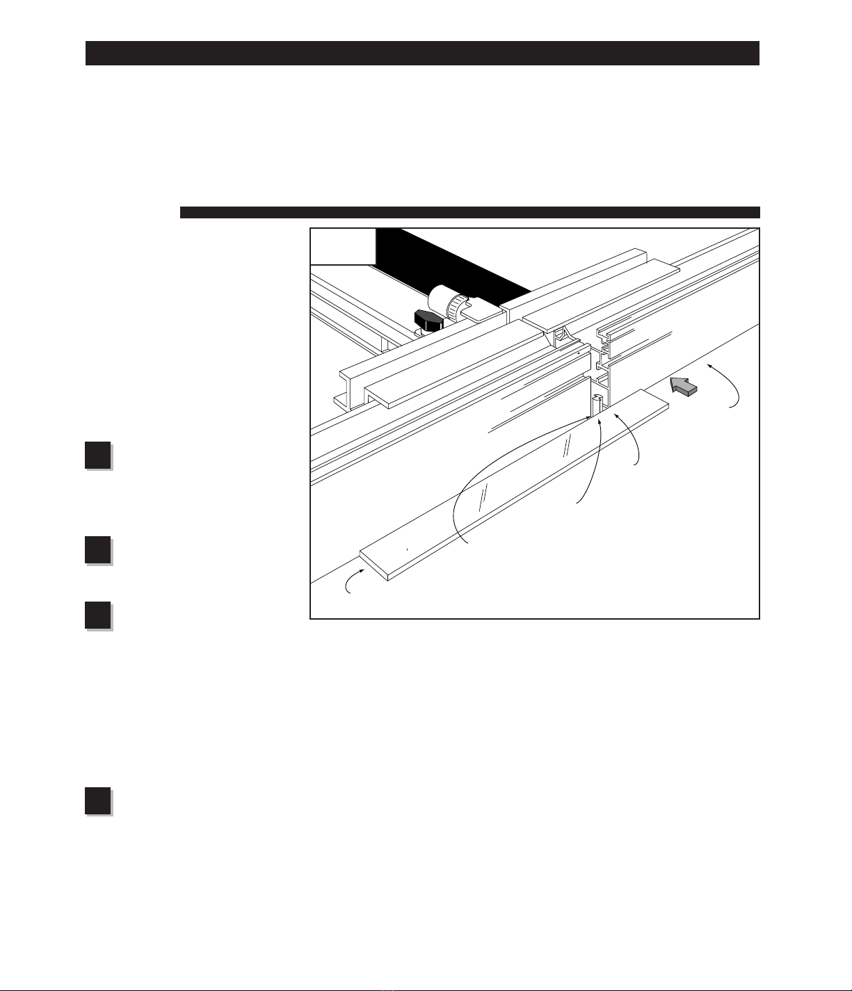
Slide the subfence into final position
Now you can slide the completed subfence into its
final position on the infeed fence and tighten the mounting
screws. Final positioning should always be done with the
router turned off and the carriage clamp locked.
CAUTION: The nature of zero clearance places the
subfence very close to the cutter. NEVER attempt to
move your fence or make any adjustments to the setup
until the router bit has come to a complete stop.
5
6
7
If you want to add zero clearance to the
outfeed fence as well, make two of the
subfences as described above. Make the profiling
cuts on both pieces from the infeed side. NEVER
make the profiling cut by sliding the subfence into the
cut from the outfeed side.
When cutting what will later become the outfeed
subfence, either drill and counterbore after completing
the profiling cuts, or make sure the counterbore faces
the infeed fence during the cut. The end of the
subfences above the profile will need to be trimmed
off so they can close around the cutter.
4Fig. 22
Offset infeed fence
3/4"
Fig. 23
Attach subfence to infeed fence
1/4– 20 x 3/4"
socket head cap screw
1/4– 20
rectangular nut
Fig. 24
Position fence
for initial
profiling cut
Stainless steel washer
Rear face of
subfence in
line with
approx. center
of cutter

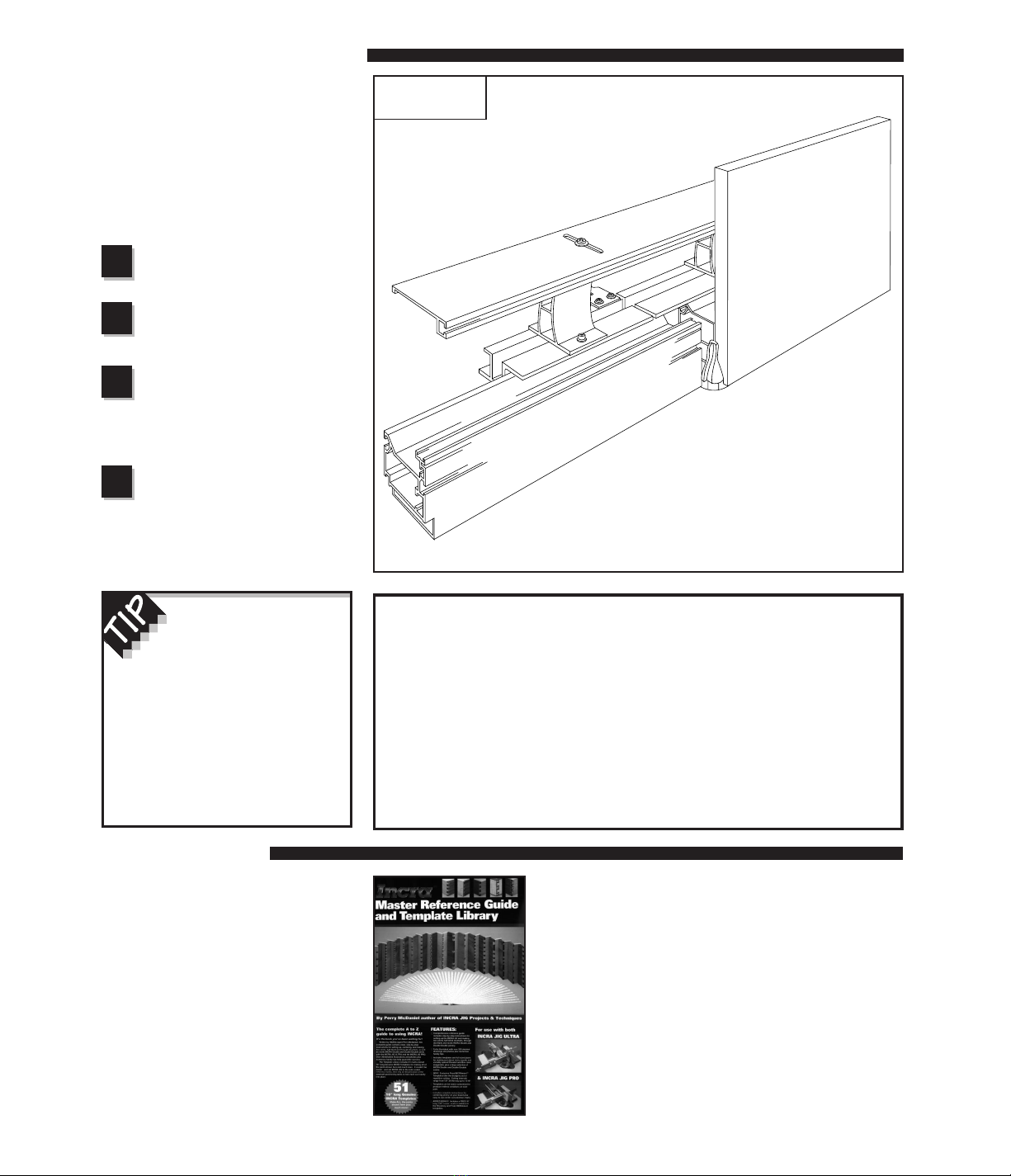
14
With the infeed and outfeed fences set in-line, your INCRA
TWIN can be used for a variety of typical fence applications
including grooving and dadoing, as well as edge forming
operations such as rabbeting, chamfering, and roundovers.
Youʼll also find the in-line position useful for many specialty
operations. With the Hi-Rise fence cap in place, youʼll be
able to use vertical panel raising bits to make raised panels
for cabinetry, and since its design is compatible with all
INCRA joint-making accessories, youʼll be able to cut
countless varieties of box joints and dovetails.
IN-LINE FENCE APPLICATIONS
Fig. 25
General purpose fence
General Purpose Fence
The essence of any INCRA JIG is its ability to accurately
position your board for a cutting operation. In a nutshell, it is
a precision fence system. Even when used as a joint maker,
the fact is that you are simply applying a particular method of
work to a very accurate fence system to produce the many
possible joints. Above all else, the INCRA TWIN gives you
the ability to make a cut exactly where you want it.
Using the TWIN as a general purpose fence is just as easy
as using any other fence in your shop. In fact, it shares in
common four things that all fences have: the straight edge or
fence that your board will be pushed along as you make a
cut, a scale, a hairline cursor, and a clamp. You will use your
INCRA fence as you would any fence. That is, first youʼll
unclamp the carriage clamp then youʼll look through the
hairline cursor as you move the fence. When you see your
measurement come under the hairline, youʼll clamp the
fence in place.
Of course, this is where the comparison ends, because unlike
other fences, when you clamp the TWIN in place, it is exactly
where you want it to be. Just get the mark on the scale close
to the hairline cursor and the Automatic Positioning Control of
the patented INCRA sawtoothed racks moves the fence to the
exact location as you pull the carriage clamp up to lock the jig
in place. It really is that easy. Youʼre sure to find many cutting
situations in the shop where the precision of the TWIN will
benefit you and your work.
“Zeroing” the Fence to Your Router Bit
In order to ensure accurate cutting results from any fence for
general purpose routing, the fence must first be “zeroed” to
the cutter. To zero your INCRA TWIN, unlock the carriage
clamp and slide the fence up to the edge of the cutter. Sight
down the length of the fence to check for a gap between the
fence and the cutter. Fine-tune any remaining distance by
micro adjusting the fence position. When the gap of light
disappears, the cutter will be “zero” distance from the fence.
Check to make sure that the router bit is safely centered in
the opening in the fence. Return the carriage clamp to the
locked position, then slide the 1/32" scale to read 0" under the
hairline cursor.
Fig. 26
Zeroing the fence to the cutter
For a truly precise “zeroed” setup, follow the
instructions above, then move the fence to a scale
reading of 1/4" and make a test cut on a piece of
scrap stock. (Make sure the scrap stock has a
square edge and that this edge is against the
fence during the cut.) Use a pair of machinist
calipers to measure the distance between the
groove and the edge of the board. If it does not
measure exactly .250", just use the micro adjuster
to accurately fine-tune the remaining distance.
Micro adjust fence until
gap of light between
fence and cutter
disappears
After positioning the fence at zero
distance from the cutter, slide the scale
to read 0" under the hairline cursor
15
Safety Reminder
❐Whenever using large diameter vertical or horizontal panel raising bits
or any other large diameter bit, always follow that router bit
manufacturerʼs operation and safety recommendations.
❐Whenever it is necessary to remove large amounts of stock, always
use multiple side-by-side passes to achieve the final cut. Several
shallow cuts are safer and will yield better results.
Vertical Panel Raising
The introduction of the vertical panel
raising bit has made cutting this all-
important component of frame and panel
construction a relatively simple operation
for the router table. Youʼll find your
INCRA TWIN with its built-in dust
collection, adjustable fence gap, and
Hi-Rise fence cap perfect for this
operation. The setup is as follows:
Install vertical panel
raising bit and set
appropriate depth of cut
Adjust fence gap as
necessary
See gap adjustment on page 12.
Attach the Hi-Rise fence
cap
Use a straightedge to adjust the cap in
line with the front of the fence. (see
Fig. 6 on page 5.)
Sneak up on the final
width of the cut
Do not make the full width of the cut in a
single pass. Instead, use several light
side-by-side passes, moving the fence
back 1/16" or so after each pass.
Fig. 27
Vertical panel raising
4
2
3
1
Joint Making
Joint making represents one of the
most exciting applications for your
INCRA TWIN. Just by applying a little
technique to the accuracy of the TWIN,
youʼll be able to add joinery for box
and drawer making to your list of shop
skills. The INCRA
Master Reference
Guide & Template Library
included in
the INCRA TWIN system package is a
complete source book for joinery,
including step-by-step instructions for
box joints, half-blind dovetails, through
dovetails, the INCRA double dovetail
and the double-double box joint.
A zero clearance
subfence will greatly reduce
tearout and increase support
for all cutting operations. See
page 12 for information on how to
make and use this handy item. To
use the fence cap in conjunction
with a zero clearance subfence,
mount the cap upside down with
the T-slot still facing forward.
16
Jointing
Most woodworking projects require
that your boards begin with at least
one straight edge. This one edge
then becomes the reference surface
for subsequent perpendicular or
parallel cuts. By using your INCRA
TWIN and the setup described below,
youʼll be able to put a perfectly
straight edge on your board at the
router table, and because of the
higher RPM of the router, youʼll find
the freshly jointed edge far smoother
than any jointer machine can produce.
Install a straight bit
Install a 1/2" diameter (or larger)
straight bit and set the depth of cut to
slightly greater than the thickness of
your stock.
Adjust fence gap as
necessary
See Gap Adjustment on page 12.
Set initial fence
position
Unlock the carriage clamp and slide
the fence up to the cutter. Adjust the
location of the fence to position the
outfeed fence in line with the
outermost cutting arc of the router bit.
A straightedge placed against the
outfeed fence can be used to help
align the fence with the cutter, see
Fig. 28.
Offset infeed fence
Set the desired infeed fence
offset by adjusting the infeed fence
backward. (See Infeed Fence
Adjustment on page 10.) Moving
the infeed fence back about .015"
(1/2turn clockwise with the black
micro adjust knob) should produce a
smooth cut.
OFFSET FENCE APPLICATIONS
4
2
3
1
Fig. 28
Jointing
One of the most valuable features of
the INCRA TWIN LINEAR is the ability
to offset the infeed and outfeed
fences. The offset fence adds a whole
new dimension to the router table,
allowing it to perform two new
operations: jointing and shaping.
First:
Install 1/2" dia. or larger straight bit
Second:
Adjust fence gap as necessary
Straightedge
Third:
Position TWIN to align fence with
the cutting wing on the router bit
Fourth:
Offset infeed
fence backward
about .015"
(1/64")
17
Shaping
Many shaping operations involve
the removal of the entire edge of a
square piece of stock as it is
moved past the cutter. With a
careful offset fence setup, a
shaping operation can
simultaneously straighten or joint
the shaped edge. Hereʼs how:
Install router bit
Set desired depth of cut
Adjust fence gap as
necessary
See Gap Adjustment on page 12.
Set initial fence
position
Unlock the carriage clamp and
slide the fence up to the cutter.
Adjust the location of the fence to
position the outfeed fence in line
with the outermost cutting arc of
the smallest diameter on the cutter,
Fig. 29. A thin straightedge held
against the outfeed fence can be
used to help align the fence with
the smallest diameter of the cutter.
Fig. 30
Set the desired fence
offset
Set the desired fence offset by
adjusting the infeed fence
backward. (See Infeed Fence
Adjustment on page 10.) Moving
the infeed fence back about .015”
(1/2turn clockwise with the black
micro adjust knob) should produce
a smooth cut.
4
2
3
1
Fig. 29
Set initial fence position
Fig. 30
Shaping
See page 12 for
information on how
to make a zero
clearance subfence
for your shaping
operations.
Align outfeed
fence with the
smallest diameter
on the cutter
Third:
Position TWIN to align with smallest diameter on the cutter
Fourth:
Offset infeed fence
backward about
.015" ( 1/64")
Thin straightedge
Note: View from outfeed side of table
First:
Install router bit
Second:
Adjust fence gap as necessary

18
ADJUSTMENTS
All of the components and features of
your new INCRA TWIN LINEAR have
been factory set and should require no
further attention. If, however, you wish
to adjust or recalibrate these
components, the following information
is provided to assist in performing the
adjustments.
NOTE
The INCRA TWINʼs base must be attached to the router
table with all eight mounting screws (see Fig. 3 on page 4.)
before adjusting the clamping pressure.
The INCRA TWIN LINEAR carriage
clamp was designed to make it easy
for the operator to adjust the clamping
pressure to his own individual
preferences using the supplied clamp
pad shims. Hereʼs how:
Unlock the carriage clamp. Remove
the small phillips head screw, washer,
and “L” shaped plastic clamp pad
retainer located just to the right of the
clamp (see Fig. 31). Leave the hex
nut in place in the T-slot below. Your
ownerʼs manual hardware pack
contains (3) .005 X 7/8" x 4" clamp
pad shims. If you want to increase
the clamping pressure, add one of the
shims into the clamp pad slot shown
in Fig. 32. Check the clamping
pressure and adjust further as
necessary. The shims should be
placed to the left of the 1/8" clamp pad
shown in Fig. 32 so that the clamp
always touches the 1/8" pad, not the
shims. To decrease the clamping
pressure, remove one of the existing
thin shims. When you are satisfied
with the clamping pressure, replace
the plastic clamp pad retainer and
secure with the screw and washer.
The screw is long enough to start into
the hex nut without removing the nut
from the T-slot.
CAUTION: Whenever making
clamping pressure adjustments,
always make sure that
adequate pressure remains to
hold the carriage rigidly in
place when clamped in the fully
extended position.
Fig. 31
Clamp pad retainer removal
Carriage clamp
unlocked
Fig. 32
Adjusting the clamping pressure
Add or remove shims to
the left of 1/8" clamp pad
Carriage not shown for clarity
1/8" clamp pad
Adjusting the Clamping Pressure
Clamp pad retainer

19
On the side of the outfeed (gold) carriage youʼll notice (4)
sawtoothed INCRA racks. To realign these racks, loosen
the phillips head screws that hold the forward (3) racks in
place. Do not loosen the screws on the rack at the rear
end of the carriage. Position the carriage in the base so
that when the carriage clamp is pulled up into the locked
position, the short clamping rack bridges the gap between
the already tightened rear rack and the second rack. See
Fig. 33. Tighten the one mounting screw you have access
to. Then unlock the carriage clamp and slide the carriage
Fig. 33
Realigning carriage racks
forward to tighten the other screw. Continue with this
bridging and tightening operation between racks #2 and
#3, then finally between #3 and #4.
Realign the fence racks in the same way that the
carriage racks are aligned. Leave one of the two racks
on each fence in place while loosening the screws on the
other. Bridge the gap between the loosened and
tightened racks using the INCRA Stop, then tighten the
two screws on the loose rack.
Loosen the (4) socket head cap screws that secure the
infeed fence mounting bracket to the infeed (black)
carriage, Fig. 34. Using a reliable straightedge, hold both
the infeed and outfeed fences against the straightedge and
tighten the (4) screws a little at a time until all are secure.
Adjusting the fences square to the table is done by
loosening the same (4) socket head cap screws and
placing shims between the fence mounting bracket and
carriage. Fence squaring adjustments may be performed
as necessary to one or both fences.
First:
Loosen screws on forward 3 racks
Second:
Position carriage so that short clamping rack bridges
ends of rear and second rack, then clamp in place
Approx. 5/16"
Do not loosen screws on rear rack
Fig. 34
Realigning
infeed and
outfeed fences
Infeed fence
Loosen (4)
socket head cap
screws on infeed
fence mounting
bracket
Realigning the Carriage and Fence Racks
Realigning Infeed and Outfeed Fences
NOTE
Before realignment, make sure to remove any offset
that may exist between the infeed and outfeed
fences and lock the carriage clamp in place.
Third:
Tighten screw then reposition
carriage to tighten other screw
Fourth:
Repeat bridging and tightening
operation for remaining racks
Use a reliable
straight edge
to realign
infeed fence
to outfeed
fence
Outfeed fence
20
Made in the U.S.A.
Taylor Design Group, Inc. • P.O. Box 810262 • Dallas, TX 75381
© 1997, Taylor Design Group, Inc. INCRA is a registered trademark of Taylor Design Group, Inc. 0997
PARTS AND OPTIONAL ACCESSORIES
PRODUCT INFORMATION
For a product information update on the complete Incra line
of tools, please see your nearest dealer. If you are unable to
locate a store nearby, or if you have trouble finding a
particular product, we will honor your order directly.
For a product information brochure, call, write or fax to:
Taylor Design Group, Inc.
P.O. Box 810262, Dallas, TX 75381
Tel: (972) 418-4811 Fax: (972) 243-4277
Web Site: www.incra.com
WARRANTY
Taylor Design Group, Inc. warrants this product for one year from date of purchase. We will repair any defects due
to faulty material or workmanship, or at our option, replace the product free of charge. Please return the failing
component only, postage prepaid, along with a description of the problem to the address below. This warranty does
not apply to parts which have been subjected to improper use, alteration, or abuse.
LIFETIME WARRANTY ON POSITIONING RACKS
If an Incra positioning rack in this tool becomes damaged for ANY reason, Taylor Design Group will replace it free of
charge for as long as you own your tool. Return the damaged rack, postage prepaid, and allow 1 to 2 weeks for delivery.
NOTE:
Replacement parts cannot be sent unless damaged racks have been received by Taylor Design Group.
Part # Part Description Price
TL-CURSOR Hairline Cursor (with mounting hardware) $ 7.95
ISTOP Stop Positioner (with mounting hardware) $22.95
IEXT18 18" Stop Extender Bar with auxiliary stop, scale and hardware $15.95
IJPT1
Incra Jig Projects & Techniques Book
$22.95
Features 14 original Incra projects, 4 exclusive new Incra joints,
and a wealth of tips and techniques that will help you master the Incra Jig
TL-SCALE16 16" long 1⁄32" Lexan®floating scale $ 2.95
TL-SCALE21 21" stainless steel primary scale $ 9.95
TL-SCALE31 31" stainless steel primary scale $14.95
Taylor Design Group, Inc.
P.O. Box 810262, Dallas, Texas 75381
Tel: (972) 242-9975 Fax: (972) 242-9985
www.incra.com
Table of contents
Other Incra Tools manuals


Popular Tools manuals by other brands


BGS technic
BGS technic 8716 instruction manual

Berner
Berner Tornador BPT-TG B011 instruction manual

UTILCO
UTILCO UtilPro BLL-95CU-PS instruction manual

Schill
Schill FT 260 Installation and operating instruction

Harbor Freight Tools
Harbor Freight Tools 95878 Assembly and operation instructions

Cornwell Tools
Cornwell Tools blue POWER CAT851XLR operating instructions


