© 3M 2020. 7
Operation
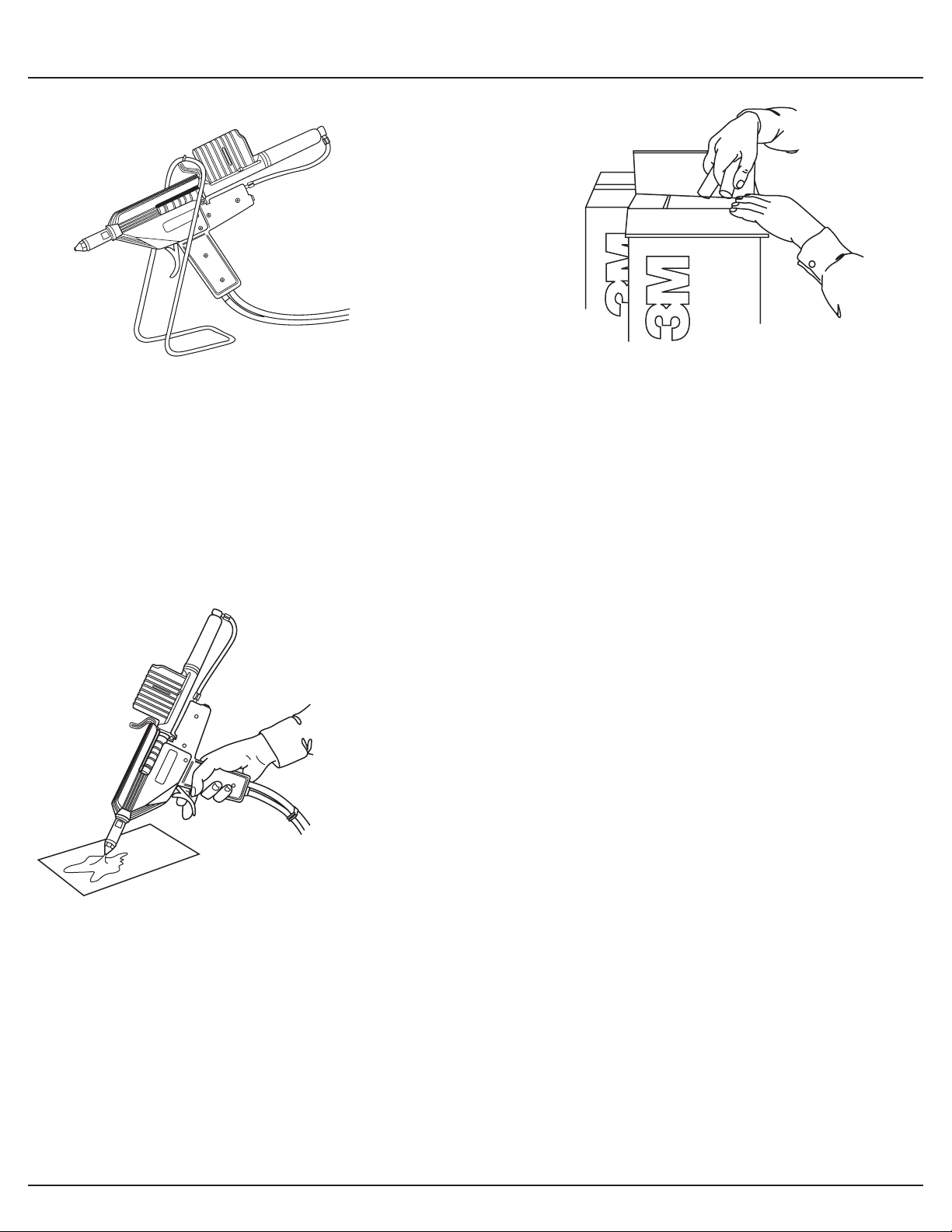
Warmup
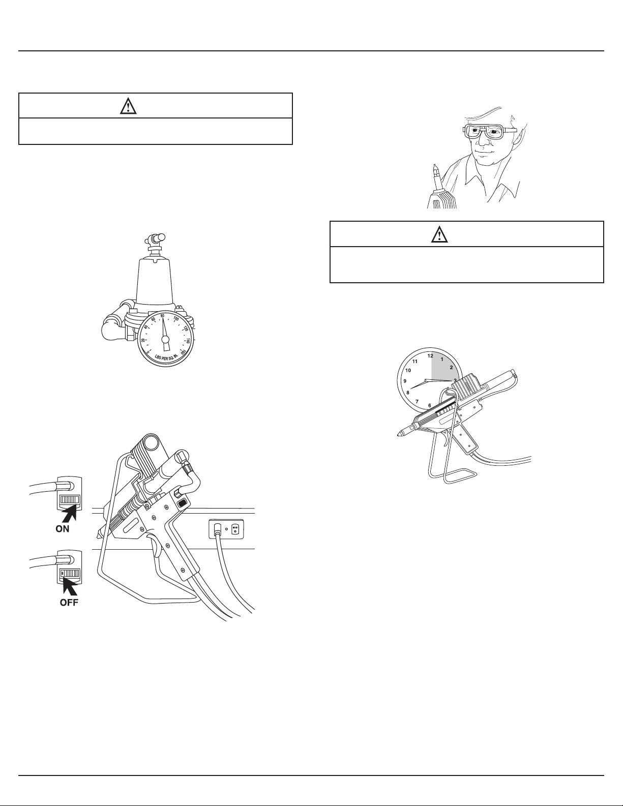
Make certain that the 3M™ Hot Melt Applicator PG II is
fully loaded with adhesive. Set the o/on switch to the
“on” position, switch should light up, and set 3M Hot Melt
Applicator PG II in the bench stand for 15 minutes. During
this warmup period you may note a slight dripping from
the nozzle tip. This dripping is due to expansion of the
adhesive during warmup.
Loading
After warmup, load applicator with the 3M™ Hot Melt Adhesive
you’ll be using on the job. To do this, fully retract the Speedloader
piston by pulling one of the retract knobs located on either side
of the loading chamber. Insert up to three 3M Hot Melt Adhesive
Sticks into the chamber through the rear loading port. The
applicator is now ready for operation.
As adhesive is extruded, the piston will move forward. This will
be visually evident by the forward movement of the retract knobs.
As the piston approaches the front of the chamber, a whistling
sound will be heard. At this point the piston may be retracted
and another adhesive stick will fall into place. Applicator is again
ready for operation. Adhesive may be loaded into the chamber
via the rear port at any time during operation thus saving time and
increasing productivity.
If it is desired to remove adhesive once it is in the loading chamber,
simply roll the applicator to one side and then point up. This will
allow the adhesive to roll up and out of the chamber.
In order to keep the Speedloader stick feed operating at maximum
efficiency, the chamber should be sprayed inside while the piston
is in the full forward position with 3M™ Silicone Lubricant or
equivalent once a week.
CAUTION
Never pull the trigger on the applicator unless there is adhesive
in the loading chamber.
Application
Get a feel for your new 3M Hot Melt Applicator PG II. Start by
applying small amounts of adhesive in puddles on a piece of scrap
or paper. Try feathering the trigger. The 3M Hot Melt Applicator
PG II is unique in this respect. Pull the trigger back slowly and note
a small discharge of adhesive; pull the trigger back more and note
increasing adhesive flow. When the trigger is fully depressed;
you will get maximum flow. If more or less flow is desired, refer to
page 19 of this manual.
NOTICE
Never operate the applicator without a nozzle tip. Doing so
could seriously damage the nozzle valve.
Changing Tips
The 3M Hot Melt Applicator PG II includes two different tips as
standard equipment. Other tips, available from your 3M Hot Melt
Adhesive distributor, are shown on page 19 of this manual.
WARNING
Disconnect air and electrical power before servicing. Wear heat
resistant gloves while working on tips.
Tips can be changed only when the applicator is hot. You will
need a 5/8" (16 mm) and a 1/2" (13 mm) open-end wrench.
Hold the nozzle valve hex firmly with the 5/8" (16 mm) wrench,
while removing the nozzle tip with the 1/2" (13 mm) wrench.
The accessory tip is mounted using the reverse procedure.
Snug the tip lightly.
NOTICE
Overtightening could damage the valve assembly.