3
Product note
Base holder for boring slide
W9800029EN-02.02.18
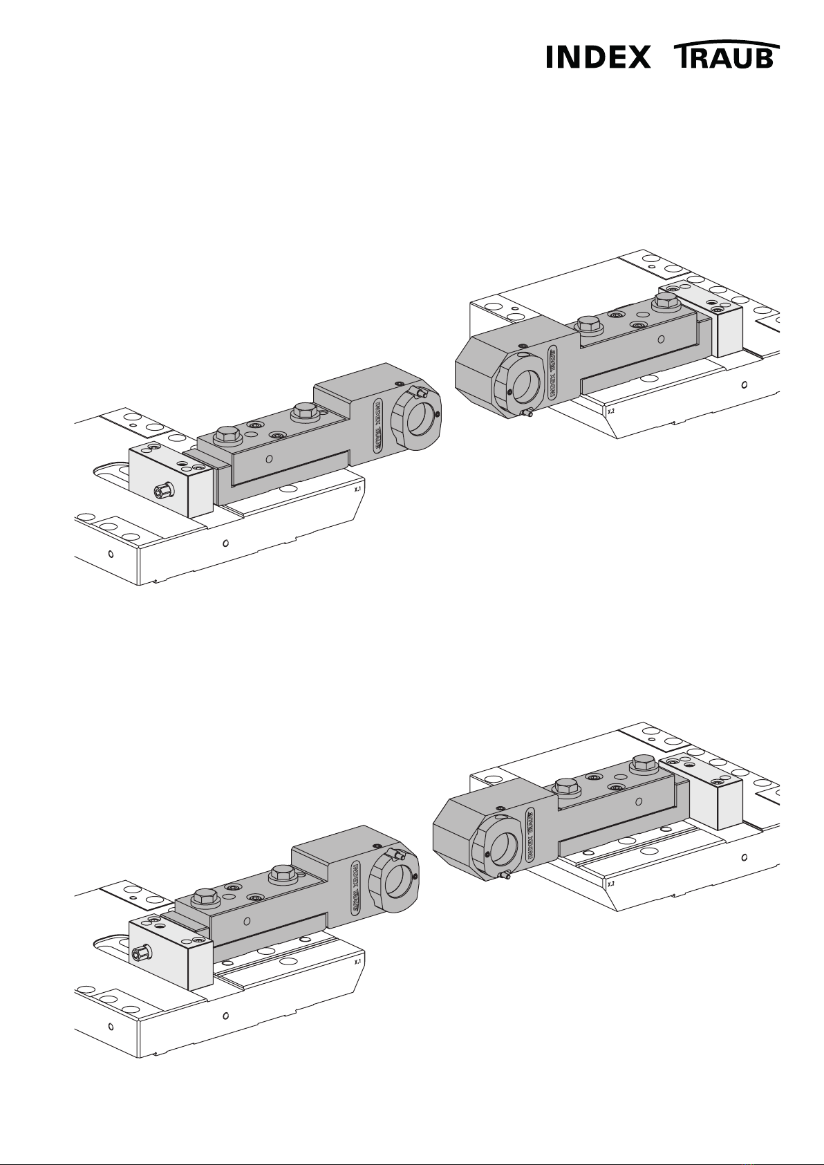
Setup options on boring slide
Z+ orientation ................................................................................................................................................................ 5
Z- orientation.................................................................................................................................................................. 5
Base holder 10156937
Position X.2, delivery state .......................................................................................................................................... 6
Position X.1, conversion................................................................................................................................................ 7
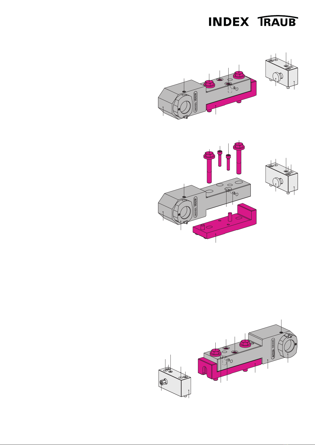
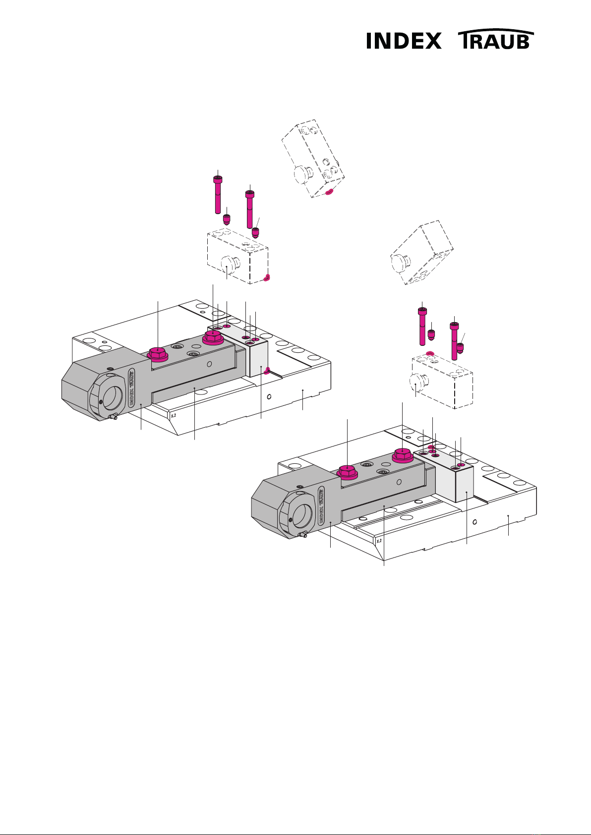
Setup on boring slide
Position X.2, Z+ orientation ......................................................................................................................................... 8
Position X.1, Z- orientation............................................................................................................................................ 9
Conversion Z orientation, 30 mm offset .................................................................................................................... 10
Inserting the drill holder................................................................................................................................................ 11
Axis orientation................................................................................................................................................................ 12
Y orientation by hydraulic expansion clamping sleeve
Optimum conditions ..................................................................................................................................................... 13
Cleaning.......................................................................................................................................................................... 13
Clamping ........................................................................................................................................................................ 13
Temperature................................................................................................................................................................... 13
Storage ........................................................................................................................................................................... 13
Adjustment..................................................................................................................................................................... 14
Adjusting concentricity.................................................................................................................................................. 15
Adjustment to below 0.005 mm ............................................................................................................................... 16
Alignment in X- spindle center .................................................................................................................................... 17
TABLE OF CONTENTS