Individual Computers Indivision AGA MK3 1200 How to use

Indivision AGA MK3 1200 short manual
Dear customer,
thank you for purchasing a product from Individual Computers. We're sure that your new
flickerfixer will satisfy all your needs. However, we would like to emphasi e that installing
the product in an A1200 is not easy, and it requires some skills. Please make sure that
you have enough light at your desk!
Installing the flickerfixer should only be done by experienced persons. If you have never
opened your computer before, you should seek help from a technician.
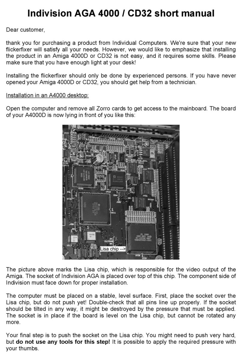
Open the computer and remove the disk drive, the harddrive and the RF shield. Carefully
put the keyboard to the back of the computer, so there is no mechanical stress on the
cable. The main board of your A1200 is now lying in front of you like this:
The picture above marks the Lisa chip, which is responsible for video output. The brown
socket of Indivision AGA is placed over top of this chip. The cable connection of Indivision
AGA MK3 must face to the right.
The mainboard of your A1200 must be placed on a stable, level surface. First, place the
socket over the Lisa chip, but do not push yet! Double-check that all pins line up properly.
If the socket should be tilted in any way, it might be destroyed by the pressure that must
be applied. The socket is in place if the board is level on the Lisa chip, but cannot be
rotated any more.
Your final step is to push the socket on the Lisa chip. You might need to push very hard,
but do not use any tools for this step! It is possible to apply the required pressure with
your thumbs. The unit snaps into place with an obvious latching sound.
Do the same for the CIA adapter, which must be placed on U7 of the A1200 (A4000T:
U550). Now you can attach the cable to the black connector of Indivision AGA MK3 and
route it in the computer as shown in the following picture:

Mount the HDMI/VGA-adapter with the included screw and
nut with the connector facing outside that you intend to
use. Only one output may be used at a time! The adapter
should be mounted left-aligned, so the A1200 lower shield
will give it additional mechanical stability. The screw sits in
place very firmly. This is intentional. Make sure that the
cable is not squished in any way. Should you choose the
routing like in the picture above, please be especially
careful when re-installing the disk drive. It might be
necessary to modify the lower RF shield so the flat cable
won’t be cut by the lower shield.
We recommend to put the upper RF shield back on. This is of course only possible with
modifications. Please cut a hole into the RF shield with an appropriate tool, so there will be
no shorts with Indivision AGA MK3. Operating the computer without the upper RF shield is
possible, but might result in EM noise and probably even in random computer crashes. If
your computer is in a tower, then the mount holes of the HDMI/VGA adapter should be
connected with any metal part of your case. If your tower case is made of plastic, you
should replace it with a metal case.
You do not need a driver to operate Indivision AGA MK3, therefore we haven't included a
disk. y pressing left-shift, CTRL and Tilde (left of the 1-key) at the same time, you
enter “live config mode”: Move the mouse to position the picture. Hold down the left
mouse button and move the mouse to oom in or out. Press Tilde one more time to leave
live config mode. These settings are temporary, they are not saved in the flash of your
flicker fixer.
For more sophisticated adjustments and possible flash updates, please download the
configuration tool from https://wiki.icomp.de. This will also allow you to persist the
changes you’ve made with the “live configuration”.
Indivision AGA MK3 is configured at the factory to output a picture that can be displayed
by most common HDMI- and VGA monitors, so you can start working right away.
However, we recommend to download the config tool and optimi e the output according to

your monitor’s capabilities, which will be detected automatically. There is no need for
expert knowledge to enter data like frequencies, resolutions and similar settings.
You can set almost any screenmode on the graphical desktop of your computer using the
prefs/screenmode program. The only exceptions are A2024 screenmodes which cannot be
displayed on Indivision AGA MK3. Of course there are some modes of questionable
usefulness (for example „Super72“ at 800 by 150 pixels), but if you prefer resolutions like
this, Indivision AGA does not limit you in any way.
In addition to standard screenmodes, Indivision supports the HighGFX driver at 1024x768
or 1280x720 pixels which can be found on Aminet in the directory driver/moni . Even
the “XTREME” driver with 1280x1024 pixels can be used.
The brown socket of Indivision is mechanically altered in order to have a better fit on the
Lisa chip. Traces of machining are clearly visible, and do not affect proper function in any
way.
You will surely operate your graphical desktop at a higher resolution than you did before
you installed Indivision AGA MK3. Please be aware that this is pushing the chipset to it's
limits, and it may reveal a weakness of the chipset in some cases. On some mainboards,
you may see pixels flickering depending on temperature. This flickering may get better or
worse after the computer has warmed up. This is not caused by Indivision AGA MK3, but it
also happens without the flickerfixer and it's visible on a 15kH monitor. These errors only
become visible through Indivision AGA MK3.
Should you observe this behaviour, Indivision AGA MK3 offers a few adjustments in the
config tool that influence chipset timing in a positive way. Please read the documentation
of the config tool for any details about chipset fixes without soldering – describing these
here would go beyond the scope of this short manual.
Installation in A4000T
In an A4000T, capacitor CE164C gets in the way. It should be replaced by a lower-profile
ceramic capacitor before Indivision AGA MK3 is installed. Please have this modification
performed by a technician. It is possible to install the flicker fixer with the original part in
place, but this put mechanical stress on the unit and should not be left in place for more
than ten minutes (that is: only for testing purpose).
For installation in an A4000T, the CPU board must be removed. The Lisa-chip is located
near the keyboard connector. The connectors for cables of Indivision AGA MK3 face to the
front of the computer (that is: Towards the SIMM slots of the computer). Indivision AGA
MK3 has a small hole near the Lisa-socket that gives way to the PAL/NTSC jumper.
The CIA-adapter must be placed on U550 of the A4000T – that’s the CIA chip right next to
the 50MH oscillator on the main board. Please look at the picture on the following page
for the correct orientation of the adapter. For most other orientations or the “wrong CIA
chip”, the cable to the main flicker fixer would be too short.

Support
If you need assistance with your flickerfixer, there is a support forum at
https://forum.icomp.de. Please mind that this is the only way that we provide
support for our products. Support questions that reach us by e-Mail will either not be
answered at all, or you’ll get a link to the support forum as an answer. Please understand
that any other support method would only mean added work for us. Especially frequently
asked questions are easily answered in our support forum, as we have a search function
that actually works. Please try it!
© 2008-2020 individual Computers Jens Schönfeld GmbH. For use in private environments. Not designed,
authori ed or warranted for use in life support systems or other critical operations.
Names and other trademarks referred to within this manual are property of their respective trademark
holders. We're not affiliated with any of the mentioned trademark holders.
Individual Computers Jens Schönfeld GmbH
Im Zemmer 6
52152 Woffelsbach
Germany
Good hardware for good computers.
Table of contents
Other Individual Computers Desktop manuals

