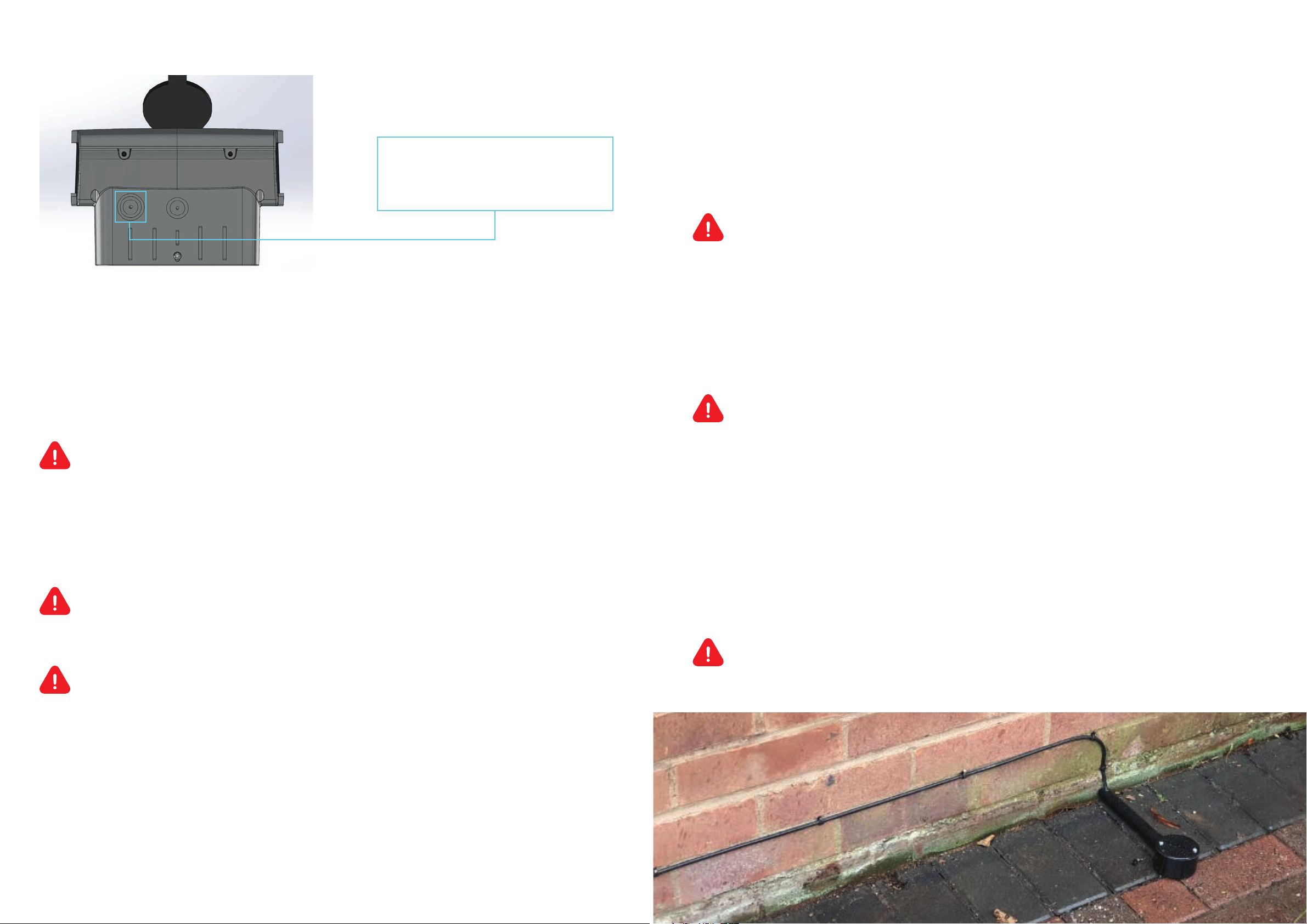
INDRA Smart PRO User manual

01684 770 631
hello@indra.co.uk
www.indra.co.uk
Sparrowhawk Close, Enigma Business Park,
Malvern, Worcestershire, WR14 1GL
This guide is designed to enable the installation of Indra
Smart Chargers in accordance with the Electric Vehicles
(Smart Charge Points) Regulations 2021
Installation Guide for
Electric Vehicle Smart Charge
Point Regulations Compliance
Electric Vehicles (Smart Charge Points) Regulations 2021
From https://www.gov.uk/guidance/regulations-electric-vehicle-smart-charge-points:
Electric vehicle charge points sold in Great Britain with private (domestic or workplace) use are being
regulated to help manage the increase in electricity demand from the transition to electric vehicles.
The regulations ensure charge points have smart functionality, enabling the charging of an electric
vehicle when there is less demand on the grid, or when more renewable electricity is available. The
regulations also ensure that EV charge points meet specified device-level requirements, enabling a
minimum level of access, security and information for consumers.
The Electric Vehicles (Smart Charge Points) Regulations 2021 is the underpinning legislation.
Extent of obligation
The regulations come into force on 30 June 2022, with the security requirements set out in Schedule 1
of the regulations, coming into force on 30 December 2022.
The regulations apply to any person or business selling, offering, or advertising an EV charge point
for sale. The regulations also apply to exchanges under warranty if the exchange is made after 30
June 2022.
Installer requirements
The requirements that the charge point must conform to are detailed below. Indra smart chargers
conform to the requirements when installed according to the Installation Guide (May 2022) and
using charger’s firmware version 10.x or greater when installed. This includes three changes to
the orginal installation steps:
1. Check the charger’s firmware version is version 10.x or greater
2. Fit a numbered security tag and log the tag number in the Installer App
3. Issue the Statement of Compliance to the customer once the installation is complete
1. Check Software Version
Check the charger’s firmware is version 10.x or greater. If it is not, then update the firmware to the
latest version.
Hint: Keep a long ethernet cable in the van to allow temporary connection to a router for rapid software
updates. For example a £20 Reel Flat Black CAT7 from Amazon:
https://www.amazon.co.uk/dp/B09244HLW9

2. Security Tag
A security tag is provided with Indra chargers. The tag
should be fitted to the charger once installation has been
completed and before the facia is fitted – see image.
The number on the security tag should be recorded during the installation
in the Installer portal or via Indra support.
Requirement: The fitting and recording of the security tag is a legal
requirement so the installed charger is compliant with the Electric Vehicles
(Smart Charge Points) Regulations 2021.
3. Statement of Compliance
The Statement of Compliance is provided in the charger's welcome pack.
This must be completed by the seller, signed, and given to the customer
at the end of the installation.
Requirement: The completion and issue of the Statement of Compliance Is a
requirement of the Electric Vehicles (Smart Charge Points) Regulations 2021.
What changes Indra’s has made to be compliant with the regulations?
Indra has made a number of changes to Indra chargers for compliance with the
June Electric Vehicles (Smart Charge Points) Regulations 2021. These include
updating the charger’s firmware to version 10.x. When used with the Indra,
ev.energy, or Kaluza App, firmware version 10 meets the additional
regulatory requirements, including metering, a randomised delay solution,
and off peak scheduling. In addition, the installation process and back office management software has
been updated to comply with the regulations, for example enabling the security tag to be recorded, and
a record of sales to be securely stored.
Servicing an Indra Charger
When an Indra charger is serviced, it is necessary to first validate the security seal on the unit.
This should be done by scanning the QR code on the charger. This will take you to a portal where the
security tag status and information can be recorded. Once the service is concluded, a new security tag
can be recorded. A step-by-step process is provided in the portal.
The fitting and recording of the security tag is a requirement to ensure that the installed charger is
compliant with the Electric Vehicles (Smart Charge Points) Regulations 2021
Requirement: The security tag must be recorded in order to comply with the Electric Vehicles
(Smart Charge Points) Regulations from June 2022.
Parts
You can order a Smart Charger Regulations Spare Kit including Statement of Compliance, Charger
Regulation Installation document, Charger Tamper Seal, and CT Clamp Security Seal, from Indra to
update any chargers you have in stock. Charger Tamper Seals and CT Clamp Security Seals can also be
ordered for servicing Indra chargers.
QR Code for the Indra
Installation Manual:
QR code for the
Statement of Compliance
Document number: SMAPRWRWH002
INDRA INSTALLER SMART CHARGE REGULATION DOCUMENT
Part Numbers
SMASAFX00003 Smart Charger Regulations Spares Kit
CONPRLBSV001 Charger Tamper Seal
SMAPRCCRD001 CT Clamp Security Seal Cable Tie

INDRA Smart PRO
Installation Guide

3
Contents
General Description
Overview and Intended use environment
Protective Earth, Simultaneous Touch (PESTs) Protection
General Installation Notes
Installation Procedure
Commissioning the Unit - Smart Charging Control
Load Curtailment and Calibration
Technical Specifications and Ratings
Certification:
Safety Markings and Labels
Troubleshooting
Servicing and Maintenance
Support and Contact Information
3
3
4
10
11
29
39
52
53
54
56
57
58
Models:
190105A101 Type 1 Tethered
190105A102 Type 2 Tethered
190105A103 Type 2 Socketed
General Description
This manual describes the method of installation and hardware operation of
the ‘Smart PRO’, where the Smart PRO is a permanently installed electric vehicle
charging solution for resistive domestic and commercial loads of at least 6A
and up to 32A at 230V, 50Hz.
Smart PRO has 3 build variants:
• Smart PRO Type 1 (190105A101) has a SAE J1772 (Type 1) tethered charging
connector to be used with Type 1 socket fitted EVs
• Smart PRO Type 2 (190105A102) has an IEC 62196 (Type 2) tethered
charging connector to be used with Type 2 socket fitted EVs
• Smart PRO Type 2 Socket (190105A103) can be used with multiple types
of charging cables, provided at least one end of the cable is fitted with an
IEC 62196 male connector
Overview and Intended use environment
The Smart PRO can be classified as a ‘smart’ electric vehicle charging solution because
of its communications infrastructure which allows charging to be remotely optimised
by the Indra App or ‘Kaluza’ smart grid platform; where charging can take place when
electricity is cheapest; or if immediate charging is required, its ‘Boost’ functionality
overrides any smart grid criteria and provides instantaneous charging capability.
Charging using the Smart PRO can take place at up to 7kW, but due to
modulation capability (measured by the external CT clamp) this power
output level can also be reduced.
The Smart PRO is intended for both indoor and outdoor installation, securely
mounted to any retaining wall.
In its operating environment, the temperature must be between -20 and 50°C,
with humidity between 10% to 85% non-condensing. Supply voltage should be
230V AC at 50Hz, rated up to 32Amps, to allow for maximum charging capability.
2

Protective Earth, Simultaneous Touch (PESTs) Protection
The Smart PRO’s PEST solution can operate under four of the indents of BS
7671:2018+A1:2020+A2:2022 Amendment 1; section 722.411.4.1, for the purposes
of design/installation we have two modes of operation which INDRA call A & B.
Mode A can be configured with or without a reference electrode.
The safest installation configuration is always mode A with reference electrode
• Mode A with reference electrode – Indent iii – PME (Protective Multiple Earthing)
as CPC with a TT reference electrode and the only method for imbalanced 3 phase
installations (3 phase installations that do not meet the requirements of indent i)
• Mode B - PME as CPC with trip on L-N voltage measurement. No reference
electrode. For installations where an Earth Rod is not possible and/or there are
no simultaneous contact or touch voltage risks present. Consideration should
be given to nuisance trips where the line to neutral voltage may regularly exceed
253v, especially where local renewables are present, Mode A is less sensitive
to nuisance tripping.
• Mode A without reference electrode – For installations that do not fall under the
requirements of 722.411.4, TT installations, indoor installations, balanced 3 phase
installations (indent i), installations where PME is bonded to Earth in accordance
with indent ii and installations where protection is provided by a third party
device (e.g. matt:e).
4 5

6
BS7671. 18th Ed Am1
PEN Fault
Ref Earth Electrode
Phase Imbalance
(1) L – N Trip
(2) L – TT Ref Trip
(3) PME – TT Ref Trip
Dedicated CPC
Earth Electrode
Relay Weld detection
DC 6mA Protection
Protection for installs
with three independent
earthing systems (rare)
INDRA’s unique PEST safety features
3 phase
property capable
Touch Voltage
Simultaneous Contact
722.411.4.1 (iii)
Full protection
Full protection
230 +/- 12% RMS
230 +/- 12% RMS
30v RMS
Required – COPv4
Not required
Full protection
Full protection
Manual management
of risk
Yes
Full protection
Full protection
Limited protection
Not required
Limited protection
230 +/- 12% RMS
Faults not detected
Faults not detected
Not required
Full protection
Full protection
Manual management
of risk
Yes
Manual management
of risk
Manual management
of risk
722.411.4.1 (iv)
Limited protection
Install Method /
Operation Mode
Mode A with
Electrode
Mode A without
Electrode
Mode B
PESTs Mode A essentially works by comparing three voltage readings:
1. L - N
2. L - TT Ref
3. CPC (PME) – TT Ref
722.411.4.1 (i)
722.411.4.1 (ii)
any install not under
section 722.411.4
Not required
Limited protection
230 +/- 10% RMS
Faults not detected
Faults not detected
Not required
Full protection
Full protection
Manual management
of risk
No
Manual management
of risk
Manual management
of risk
7

98
The below scenarios show these two mode cases in the event of a fault arising on
the combined Protective Earth and neutral (PEN) conductor, leading to a potentially
dangerous voltage arising on the installation earth conductor, and any conductive
surfaces connected to the (protective) earth. In this case, the user touching the EV
(and outside tap or lamp post etc) completes the circuit back to source earth.
INDRA PESTS mode A
INDRA PESTS mode B
The main earthing terminal of the installation
is connected to an installation earth electrode by
a protective conductor complying with Regulation
544.1.1. The resistance of the earth electrode to Earth
shall be such that the maximum voltage between the
main earthing terminal of the installation and Earth in
the events of an open-circuit fault in the PEN conductor
of the low voltage network supplying the installation
does not exceed 70 V rms
Protection against electric shock in a single-phase installation
is provided by a device which electrically disconnects the
vehicle from the live conductors of the supply and from
protective earth in accordance with Regulation 543.3.3.101 (ii)
within 5 s in the event of the utilisation voltage at the charge
point, between the line and neutral conductors, being greater
than 253 V rms or less that 207 V rms. The device shall
provide isolation and be selected in accordance with Table
537.4 Equivalent means of functionality could be included
within the charging equipment. Closing or resetting of the
device shall be possible only if the voltage between line and
neutral conductors is in the range 207 to 253 V rms.
Protection against electric shock is provided b a device which
electrically disconnects the vehicle from the live conductors
of the supply and from protective earth in accordance with
Regulations 543.3.3.101(ii) within 5 s in the event of the
voltage between the circuit protective conductor and earth
exceeding 70 V rms due to an open-circuit fault in the PEN
conductor of the low voltage network. The device shall provide
isolation and be selected in accordance with Table 537.4.
Closing or resetting of the device shall be possible only if the
voltage between the circuit protective conductor and Earth
does not exceed 70 V rms. Equivalent means of functionality
could be included within the charging equipment.

General Installation Notes
Pre-Installation Checks and Warnings
Installation Procedure
Installation Kit and Tools
The Smart PRO is supplied with the general screws and wall fixings that are required
to permanently fix it in position. However, it remains the responsibility of the installer
to evaluate the suitability of the installation surface and use the appropriate fixings
when appropriate.
Tools, materials and equipment
WARNING: FAILURE TO COMPLY WITH THESE INSTRUCTIONS
COULD PRESENT A HAZARD
A) Read these instructions fully before installing or using the Smart PRO
and keep these instructions for future reference
B) The Smart PRO is designed for permanent installation and is suitable for operation
on an AC electricity supply having the same voltage and current rating as shown
on the product label.
C) The Smart PRO should be installed in accordance with extant wiring regulations;
providing protection with either an upstream Type A RCD or RCBO with 40A
overcurrent protection.
D) The Smart PRO MUST not be fitted alongside an upstream protection device which
claims to meet ident (iv) of BS 7671:2018+A1:2020+A2:2022 Amendment 1; section
722.411.4.1. Voltage upstream PEN Fault protection and curtailment devices such
as solutions from Matt:e and Garo have been proven to regularly nuisance trip and
may damage any Smart PRO device through frequent removal of the grid supply
under load.
E) A qualified professional electrician must be used for all installation and servicing
of the Smart PRO. Any servicing or tampering by a non-qualified professional
electrician will void the warranty.
F) The supply to the Smart PRO MUST be isolated before installation.
• Drill for permanent wall mounting (as applicable for wall construction)
• Spirit Level
• Wire strippers
• Smartphone, tablet or laptop to operate the “Installer App”
• Hand-held Multimeter/ Clamp meter
• UK EV Charging Station Test Adaptor Kit (including a three-pin plug socket)
• Wall fixings (as applicable for wall construction)
• Type A RCD or RCBO (40A Overcurrent Protection)
• Tri-Rated 3 Core (2P+E) Electrical cables
• 4mm2 or 6mm2 Solar Cable (EN5061), with double insulation
• Copper plated 3/8ths 4ft electrode with lug clamping terminals
• CAT5E Cable
• Torque driver (1N/m minimum setting & calibrated)
• Torx T20 Screwdriver bit
• RJ45 male connectors
• RJ45 Crimping tool
• 6 mm Bootlace Ferrule Crimps (For use on Class 5 conductors,
Not necessary for Solid Strand conductors)
• 6 mm Ferrule Crimping tool
• Cable (LAN Network) tester
• Armeg Holesaw for adding mains cable gland
• IP68 Rated Mains cable gland
• Krone/ IDC Punch-down tool
• Hacksaw (optional)
G) The Smart PRO MUST be connected to CPC reference
H) The installation location MUST be structurally sound and MUST NOT be subject
to excessive dust, vibration, lint or other material build-up which could affect
the Smart PRO’s proper operation.
WARNING: Protection against electric shock shall not be automatically reset.
10 11

1312
Procedure
Existing cables MUST be inspected for damage and ensure they are suitably rated for
the Smart PRO.
Choosing a location
• Select an installation location that ensures future servicing of the Smart PRO,
where the back plate can be mounted flush to the wall and screws can be used
to permanently secure the charger in position.
• Make sure that all ventilation channels on the Smart PRO are free from obstruction
and that the install location will not allow any flammable material to come within
100 mm of the unit.
• The socket/ cable holster of the unit must be installed between 0.75-1.20m above
ground level at the location of installation.
Ensure there is an Earth Connection to the Smart PRO.
NOTE: ANY DAMAGED OR UNSUITABLE CABLES MUST BE REPLACED
Isolate all electrical circuits and ensure they cannot be reconnected whilst
installation or servicing work is being completed. Use a proving device
where necessary.
Inspect the Smart PRO to ensure the charger has not been damaged in transit,
not compromised and is safe to connect.
If all three scenarios are green ticked, the installation can proceed. Else an alternative
device should be sought.
Ensure there is an Earth Connection to the Smart PRO.
As a precautionary step, to ensure the device has been pre-registered
on the INDRA platform and that you are unlikely to fall into commissioning
difficulties where the device is not recognised. A device check can be carried
out within the Installer App ahead of proceeding with the install.
In the Installer app, once you have selected/ input the customer details,
the QR code on the side of the device can be scanned and will verify:
1. Device format is valid
2. Device is registered
3. Device is available (not registered to somebody else)
Mounting the station
Take out the mounting bracket. Using a spirit
level, position the top of the bracket horizontally.
Then, using the bracket as a guide, mark out the
four holes for drilling and/or screwing.
Installing the bracket
Using a screwdriver secure and firmly torque four
5x35mm Pozi Countersunk head screws through
the holes of the bracket. Keep the remaining
screws for later.
Carefully remove and swing the front body to
the left-hand side, ensuring the front user interface
ribbon cable is not tensioned.
Cable tethers prevent the front body from being
completely removed.
Hanging the Smart PRO Unit
Hang the Smart PRO onto the bracket (using the
top grooves in the back of the unit) and fix to
the bracket using the M4x10 Torx Bolt, threaded
through the enclosure into the wall bracket.

14
Drilling hole for mains cable gland
After assessing what size of cable is needed to connect to the property’s electrical
supply, using an appropriate diameter Armeg Holesaw, drill a hole carefully into the
unit using the TOP LEFT dimple as a guide ONLY.
Care must be taken when drilling the hole, as the circuit board could be easily
damaged. Especially if the above advise is ignored!
When operating under PEST Mode A, a secondary reference electrode to true earth
is required. This is a Copper plated 3/8”, 4ft electrode with lug clamping terminals.
This electrode is not providing a fault path, instead it is to provide a stable
voltage measurement
• If installing straight into soil or equivalent soft terrain, then the electrode can be cut
in half, to reduce the necessary length driven into the ground. For hard aggregate,
the full four-foot length may have to be maintained.
• Using a lump hammer, or similar, drive the electrode straight into the ground.
Leaving enough length at its tip to secure the clamping terminal.
• Attach the lug clamp terminal and run a length of cable (clipping against walls
where necessary) back to the Smart PRO unit; terminate with a bootlace ferrule
in the second from right push-down terminal.
Suggested cable use either 4mm2 or 6mm2 Solar Cable (EN5061),
with double insulation
• Using a multimeter, measure the resistance of the newly installed TT electrode.
Expected resistance is 600 Ohms at 1 metre.
DO NOT use the Top Right-hand space for drilling as damage WILL occur.
Remove all shavings/ swarf from the unit and deburr the hole.
Add the gland and feed the cables through.
DRILLING OF TOP
LEFT DIMPLE ONLY IS
RECOMMENDED
Connecting Mains, Ethernet cable and External CT clamp
NOTE: ALWAYS ENSURE THE EARTH CONNECTION IS SLIGHTLY LONGER
THAN THE OTHER WIRES. THIS ENSURES IT’S THE LAST WIRE TO TAKE
ANY STRAIN.
NOTE: ALL CABLES SHOULD BE ROUTED TO MAKE USE OF ANY
PRE-EXISTING CABLE ROUTES WHERE POSSIBLE AND SO AS NOT
TO PRESENT ANY TRIP HAZARDS
Installing the TT Reference Electrode
NOTE: EACH Smart PRO DEVICE IS FACTORY SET TO MODE A VIA THE PEST
TOGGLE SWITCH. WHEN OPERATING AWAY FROM MODE A, ENSURE THIS
TOGGLE SWITCH IS FLICKED ACROSS.
NOTE: BEFORE DRIVING IN THE ELECTRODE, ENSURE A SUBTERRAIN
CHECK IS CARRIED OUT ON THE SUROUNDING AREA; SCANNING FOR
EXISTING CABLES & PIPES
NOTE: The resistance of the TT Reference Electrode is not to be confused
with the CPC Ground resistance which MUST be less than 100 OHMS to
function with EV’s which would otherwise reject charge based on High
Earth Resistance.
15

17
Example reference electrode including 4-foot rod, mechanical protection and EN5061
cable clipped direct to the wall.
• Feed the mains power cable (L, N & CPC) through the left-hand mains power gland.
• It is advised to crimp the ends of these three wires using bootlace ferrules and
connect the Live, Neutral and CPC wires to their respective Push-Down
Terminal Block.
Connecting the Mains cable
Type 1 & 2 Tethered
Charging Cable Gland
(where fitted)
Mains Power IP
Rated Gland
(not supplied)
The far-right push-down connector is for
CPC Ground
The second from right push-down connector is for
the TT Reference Electrode
The second from left push-down connector is for
Neutral
The far-left push-down connector is for
Live
(These are also denoted on the motherboard itself)
NOTE: Installation best practice, which we’ve found eases cable routing and increases
space around the IDC connections, is to ‘pig-tail’ the three cores of the mains input
cable, as shown below:
16

19
Images of ‘pig-tailed’ mains cables into the charger unit.
Image showing location and orientation of the two cores of the External CT clamp, as
wired into the IDC terminal on the Smart PRO
To connect the external CT clamp, you must push a length of CAT5e cable through the
gland and then separate the cores.
Of the eight wire cores inside the CAT5e cable, attach the blue wire and the blue/
white wire to the lower two terminals of the 4-way IDC terminal, using an appropriate
Krone tool. These core locations are also indicated via text on the PCB.
Tie the CT clamp ethernet cable to the Mains Cable using cable ties, unless routed
within conduit back to the Smart PRO unit.
Attaching the External CT Clamp
BLUE/
BE WE
4-way IDC Terminal
18

21
The External CT clamp location shall be left to the installer’s
discretion, depending on installation. However, it must be clipped around
the Live main grid supply cable and secured with the red security cable tie.
20
Note to Installer:
G100.2 will define how we do load curtailment on Smart PRO. Key changes are:
• New style CT clamps are coloured blue instead of white.
• The CT clamp now has a security cable tie to prevent removal or tampering.
• You must fit the red security cable tie around the CT clamp clasp to
prevent removal.
• If the Smart PRO does not see a CT clamp or the signal is poor quality, and you have
configured the unit for load curtailment, the unit will revert to 6A max charging to
protect the service head fuse.
Installation:
1. Use either a combined data and power cable (such as Doncaster EV ultra), or a CAT
5/6 data cable (with power run separately), terminate the blue and Blue/White
conductors into the Smart PRO motherboard IDC punchdown connector.
2. Identify where to join the CT and data cable conductors. The join should be located
within 2 meters of the CT clamp location. The connection must be mechanically
protected in a suitable enclosure such as:
• The consumer unit feeding the EV Charger (with appropriate glanding).
• A Wiska style adaptable box (with appropriate glanding).
• A WAGO style junction box.
• A standard socket box with blanking plate or data socket (if combined
with hardwired data).
3. Join the Blue and Blue/White data cable conductors to the pigtailed CT clamp
conductors using the supplied jelly crimps. Suitable lever style connectors (e.g.
WAGO) may also be used.
Data Cable Conductor
Blue
Blue and White
CT Clamp Conductor
Red
White
4. Place the CT clamp around the Line meter tail do not fit tamper protection
at this stage.

23
If the customer hasn’t opted for the 4G or Wi-Fi wireless options, the below section
relates to hardwiring a CAT5e connection back to the properties’ router.
• Push a length of the ethernet (CAT5e) cable through the left-hand gland and then
attach an RJ45 connector to its end.
• When setting up the RJ45 you must connect it in the manner below:
Looking at the male RJ45 connector from the top, going from
left to right, the wires must be in this order.
• Brown
• Brown with white
• Green
• Blue with white
• Blue
• Green with white
• Orange
• Orange with white
It is vital that the ends of the CAT5E wires are in contact with
the golden terminals at the end of RJ45 connector.
Hardwired Ethernet Link
22
Gland
CT Clamp
Picture: Join located within the consumer unit feeding the EVSE
5. Complete the commissioning process in the installer app.
6. Fit the red security cable tie (Note, this will not be supplied
until G100.2 comes into force).
Jelly Crimps
(CT and data in this
example)

2524
The other end of the ethernet cable should then be run to the house’s internet router
and cut to length.
Fit another RJ45 connector to this new end in the same manner as the previous end
and USE A NETWORK CABLE TESTER to ensure the ethernet cable is functioning
across all contacts.
If it doesn’t pass the test, then re-crimp. If it does pass, plug one end of the cable into
the female RJ45 connector on the Beaglebone within the Smart PRO and the other end
into the house’s router port.
Clip the CAT5E cable to the tethered charging cable inside the unit, to prevent risk
of crushing or damage to the Motherboard.
The below section relates to where a 4G cellular dongle or Wi-Fi dongle has been
opted for, rather than a hardwired ethernet connection.
Although the Smart PRO supports hardwired, 4G and Wi-Fi connection, it is
always advised to USE A HARDWIRED CONNECTION WHERE POSSIBLE. As 4G and
Wi-Fi connections are prone to dropping out and losing signal completely in remote
areas. The result of a network loss is that the Smart PRO will default to a constant
charging state, preventing the customer from utilising off-peak tariff periods
automatically.
Ensure the Smart PRO has the latest firmware installed to ensure the highest
performance of the 4G/Wi-Fi Dongle. Note: The fastest way to update the charger
is by connection using a hardware Ethernet cable (even if it is just temporary for the
firmware update).
PRIOR TO UNBOXING THE WIRELESS 4G/Wi-Fi DONGLE, it is important to NOTE ON
YOUR JOB CARD the unique Smart PRO device’s serial number, along with the
serial number of the dongle. This will allow pairing of, and association between,
these two products.
Smart PRO serial number will look like: 190105A10#-####### - ###
(7-digits) – (3-digits)
Wireless 4G/Wi-Fi Dongle serial identifier will look like: WCD####
(4-digit number)
Within the 4G/Wi-Fi dongle box, there should be a USB extension (460mm), a 4G
or Wi-Fi Dongle, Cable Tie Pad and 100mm Cable Tie.
Ensure the dongle is firmly pushed into the USB extension female end
Attaching the Wireless Cellular Dongle (optional)
Push the free, 90-degree male end of the USB cable into the USB socket of the Green
Beaglebone inside the Smart PRO unit (Noting orientation of the 90-degree tail)

26
CRITICAL CARE POINT
Avoid knocking any components on the PCB as serious damage may occur
Ensure the USB extension cable is neatly and tightly routed down the right-hand side.
CRITICAL CARE POINT
Ensure the USB cable is routed tight to
the right-hand side to avoid crushing and
damage when placing and securing the
enclosure front body
Peel off the 3M backing from the adhesive
mount and firmly push the dongle into the
top left-hand corner of the rear enclosure.
Screw in the six M4x10 Torx on the front body, these should
be tightened to a torque of 2.0N/m, no tighter.
Replace the Front of the Unit
27
Incorrect
routing of
the cable
Correct
routing
of cable

2928
Turn the power on at the consumer unit /breaker to the Smart PRO.
Note: If internet connectivity is not able
to be established, then after 10 mins the
device will go into ‘home alone’ mode. At
this point the logo will flash purple twice
every four seconds.
The device can be tested in this state for
basic car charging functionality only.
Smart features will not activate whilst
the device is in ‘Home Alone’ mode and
telemetry will not be received within the
Installer App detailed below. In this
instance re-check all ethernet RJ45
connections and router/ firewall
restrictions.
MAKE SURE ALL COVERS AND FIXINGS ARE IN PLACE; ALSO, THE Smart PRO
IS SECURED PRIOR TO ENERGIZING THE CIRCUIT
Turning on the unit
28
Accessing Smart Control Installer Application
To enable smart control of the Smart PRO EV charging unit, it is necessary to confirm
the commissioning of the device using the Installer Application. Installers should have
received login credentials to access the following: https://platform.kaluza.com/install.
If you are having trouble accessing the above, please contact whoever scheduled the
job for you.
Commissioning the Unit - Smart Charging Control
Installer App Pages

In the Installer App, “Find a Customer” homepage, click on the appropriate box
and enter the customer’s Last Name and the Address Postcode; then click ‘Search’.
If previously populated, the customer information should
show under “Search Results”.
• Click “Continue”.
• If the search results are blank, and you are sure that you have
entered details correctly, it is possible that a customer record
has not been created for this installation. In that case, please
contact whomever scheduled the job for you. Note: The correct
permissions are required in order to add customer information
into the Installer App (This permission will be assigned to a
company representative who will have the option to
“Create New Customer” as below)
Find your Customer
3130

32
Check the side of the unit for the serial number label. On this label there will be the QR
code and corresponding MAC address printed. To associate the installed device to the
customer account, a unique MAC Address needs to be added.
If the device you are driving the ‘Installer app’ from has a camera, then the QR code on
the product label should be scanned.
Next you will be asked to associate
a device with the customer account.
• If your camera is not working, select “Enter the Hardware ID Manually”,
in which case the 12-digit alpha-numerical MAC address must be typed
into the box.
This action will perform a few checks:
• That the format you have entered is correct
• That the device has been pre-registered for Smart Charging
• The device is not currently associated with another
customer account
• (This may be true in an instance where the unit is recycled and
has not been decommissioned from an old customer account)
• Assuming these checks are successful, click “Continue”
Add a Charger
33

3534
• The next stage is to input the “Property Max Draw” based on the DNO fuse rating at
the property. Select either 60, 80 or 100A and click “Continue”.
If the DNO fuse rating is not clear, select 60A to prevent any inadvertent damage
to/ failure of the fuse.
• To ensure ready-by times/ scheduling are met, the associated battery capacity
of the EV must be added. We ask that installers capture the customer’s vehicle
make and model information so that smart charging algorithms consider the
correct dimensions.
• Under “Add Vehicle” there is a “Vehicle Make” drop down list. Select the appropriate
vehicle manufacturer and then the specific model of EV. Click “Confirm”.
• Ensure the correct battery capacity option is chosen
• If the vehicle cannot be found in the list, you will need to “Add battery
capacity manually”
• NOTE: If you are unsure about Vehicle information, please remind the customer at
handover that they will need to enter this information in the Customer Application
for smart charging control.
Set Max House Load
Enter Vehicle Information
Other manuals for Smart PRO
5
This manual suits for next models
3
Table of contents
Other INDRA Automobile Accessories manuals
Popular Automobile Accessories manuals by other brands

Kargo Master
Kargo Master 40201 installation guide

Velleman
Velleman CAMSET28 user manual

Metra Electronics
Metra Electronics 99-7356B installation instructions

LSD-Doors
LSD-Doors 500 25 008 installation instructions

Wagan
Wagan 2537-5 user manual

Safe Fleet
Safe Fleet RVS Systems RVS-776718-BT instruction manual