Indu-Sol PROFINET-INspektor NT User manual

Indu-Sol GmbH
Blumenstraße 3
D-042626 Schmölln
Phone: +49 (0)34491 / 580-0
Fax: +49 (0)34491 / 5818-99
Email: info@indu-sol.com
Web: https://www.indu-sol.com
Our technical support team is available at +49 (0)34491 / 58 18 14, weekdays between 7:30 –16:30 (CET). You
can also email us at: support@indu-sol.com
Is your plant standing still? You can reach our emergency service around the clock at:
+49 (0)34491 / 58 18 0.

Revision overview
PROFINET-INspektor®NT - User Manual 3
Revision overview
Date
Revision
Change(s)
10/09/2015
0
First version
04/07/2016
1
Firmware Update 1.4
22/12/2016
2
Firmware Update 1.5
10/05/2019
3
Firmware Update 2.0
15/05/2020
4
Firmware Update 2.1
27/10/2021
5
Firmware Update 2.2
10/08/2022
6
Firmware Update 2.3
© Copyright 2022 Indu-Sol GmbH
We reserve the right to amend this document without notice. We continuously work on further developing
our products. We reserve the right to make changes to the scope of supply in terms of form, features and
technology. No claims can be derived from the specifications, illustrations or descriptions in this
documentation. Any kind of reproduction, subsequent editing or translation of this document, as well as
excerpts from it, requires the written consent of Indu-Sol GmbH. All rights under copyright law are expressly
reserved for Indu-Sol GmbH.
W A R N I N G
Commissioning and operation of this device must only be performed by qualified personnel. Qualified
personnel within the meaning of the safety notices in this manual are persons authorised to commission,
ground, and mark devices, systems, and circuits in accordance with safety engineering standards.
Improper use or configuration of the PROFINET-INspektor®in the network may cause severe physical
injury as well as property and material damage, also due to uncontrolled machine movements.

Contents
PROFINET-INspektor®NT - User Manual 4
Contents
Revision overview 3
Contents 4
1General information 8
1.1 Purpose of use 8
1.2 Use of Open Source Licenses 8
1.3 Scope of supply 9
1.4 General safety instructions 9
Operating personnel 9
Power supply 9
Utilization of PROFINET-INspektor®NT 9
Intended use 9
Batteries 10
2Installation 11
2.1 Device interfaces 11
2.2 Installation instructions 12
2.3 Voltage supply 13
2.4 Measurement location 13
2.5 Connection to the PROFINET network 13
Fixed installation within the master system 13
Connection via feedback-free measurement point 14
2.6 Web interface 14
2.7 Signal inputs and outputs 15
2.8 Display screen 16
3Web interface and selection functions 17
3.1 Homepage 18
Alarm overview 19
Timeline 20
Network overview 21
Node overview 22
Network statistics 24
Office network 24
3.2 Alarms 25
3.3 Switch statistics 26
3.4 Analysis 27
Netload chart 27
Contents
PROFINET-INspektor®NT - User Manual 5
Reports 27
Topologies 28
Jitter overview 28
Node statistic 29
Frame statistic 29
Tools 30
3.5 Configuration 31
System 31
General 32
Security 32
Services 34
Time and language settings 34
Network 35
Digital Input 37
GSDML Administration 38
Factory reset 39
Import/Export 39
Information 40
Monitoring 41
Node names and monitoring 41
Network state 42
Device status 42
Triggers & alarms 45
Automated report 53
Network scan and Topology determination 54
Firmware update 57
4Explanation of terms 58
4.1 PROFINET quality parameters 58
Bus node failures 58
Bus node restart 58
Releases 58
Alarm (high priority / low priority) 58
Update rate 58
Contents
PROFINET-INspektor®NT - User Manual 6
Controller Transmit clock 59
Jitter 59
Telegram gaps 59
Consecutive telegram gaps 59
Telegram overtakes 59
Load ratio 59
Error telegrams 59
Netload 59
Data throughput 60
4.2 Trigger types 60
Threshold-dependent trigger parameters 60
Status change 60
History 60
Global netload 60
Frame flood 61
New device detection 61
Double addressing 61
S7 Communication 61
Loop Detection 61
Interval 61
SNMP Trap 61
Topology 62
4.3 Other 62
IPv4 62
IPv6 62
Broadcast telegrams 63
Multicast telegrams 63
Unicast telegrams 63
ARP 63
DCP 63
MRP 63
LLDP 63
PTCP 63
PN-RT 64
PN-RTA 64
5Support and contact 65


General information
PROFINET-INspektor®NT - User Manual 8
1 General information
Please read this document thoroughly from start to finish before you begin installing the device and putting
it into operation.
1.1 Purpose of use
The PROFINET-INspektor®NT permanently monitors all data traffic in a PROFINET (PN) master system.
You will receive a maintenance requirement notification when critical changes that could lead to unplanned
system downtimes are detected.
Based on the report analysis (purely passive behaviour), the following quality parameters are monitored:
•Update rate
•Error telegrams (sent/received)
•Alarms (low and high-priority)
•Telegram gaps
•Telegram overtakes
•Bus node failure
•Bus node restart
•Jitter
•Netload (sent/received)
One PN-INspektor®NT is required per PROFINET master system. This PN-INspektor is looped into the
connection between the IO controller (PLC) and the first device (switch) for analysis, or integrated within
the network through a feedback-free measurement point (e.g. PNMA II; art. no. 114090100).
No additional IP addresses or adjustments to the PLC program are required for using the PN-INspektor®
NT. It works in an entirely manufacturer-independent way; i.e. the analysis works completely independently
of the type of control system and IO devices.
For long-term analysis, the PN-INspektor®NT can remain in the bus system without any time restrictions.
The relevant telegram traffic is continuously analysed and evaluated in order to detect deviations from
normal conditions and trigger alarms.
1.2 Use of Open Source Licenses
Indu-Sol offers to provide source code of software licensed under the GPL or LGPL or other open source
licenses requiring source code distribution. The individual licenses used in Indu-Sol products can be
found in the product front ends.

General information
PROFINET-INspektor®NT - User Manual 9
1.3 Scope of supply
The scope of supply comprises the following individual parts:
•PROFINET-INspektor®NT
•3-pole plug-in terminal block (power supply)
•6-pole plug-in terminal block (alarm contacts)
•User Quick Start Guide
•CD with software for the report analysis and device manual
Please check the contents are complete before putting into operation.
1.4 General safety instructions
Operating personnel
This device may only be put into operation and operated by qualified personnel. Qualified personnel, as
referred to in the safety-related information of this manual, are persons who are authorised to put into
operation, to earth and to label devices, systems and electrical circuits in accordance with the standards of
safety engineering.
Power supply
The devices are designed for the operation with SELV-voltages (Safety Extra Low Voltage) via LPS (Limited
Power Source). Only SELV/LPS conformal extra-low voltages according to IEC 60950-1 / EN60950-1 /
VDE0805-1 as well as power packs for voltage supplies according to NEC Class 2 (National Electrical
Code) may be used.
The shield of the RJ45-socket is connected to the device housing for dissipating interferring currents. Note
possible short circuits when using shielded cables.
Utilization of PROFINET-INspektor®NT
Do not open the housing of the device. The warranty expires when the housing is opened. The device should
be sent back to the supplier in case of any defects. There are no components in the devices, which could be
maintained by the user.
Intended use
The devices are designed for use in the industrial sector in the protection class IP20. These must therefore
not be connected directly to the public low-voltage network. The installation must be carried out in an
industrial control cabinet. The industrial control cabinet may be located at a maximum height of 3000
meters.

General information
PROFINET-INspektor®NT - User Manual 10
Batteries
Caution: Risk of Explosion if Battery is replaced by an Incorrect Type. Dispose of Used Batteries
According to the Instructions
Installation
PROFINET-INspektor®NT - User Manual 11
2 Installation
2.1 Device interfaces
Figure 1: Device ports
X5 Fault output /
digital inputs
Potential-free switch contact
Alarm acknowledgement (switch contact)
1
2
Alarm deactivation (configurable)
3
reference ground for 1–3
GND
Alarm acknowledgement (Web + switch contact)
System display
RJ45 PROFINET ports
X4 Power supply
24 V DC + PE
RJ45 network port
PROFINET
X1/P1 IN
X1/P2 OUT
Web interface
X2 ACTIVE
X3 PASSIVE
Installation
PROFINET-INspektor®NT - User Manual 12
2.2 Installation instructions
PROFINET-INspektor®NT is installed horizontally inside the cabinet on a 35 mm top-hat rail in accordance
with DIN EN 60715.
Figure 2: Device installation on top-hat rail
Caution: The following distances must be maintained from other modules for correct installation:
•From left and right: 20 mm
•From top and bottom: 50 mm
Removal for alternate use of the PN-INspektor®NT in different master systems is illustrated in Figure 3.
Figure 3: Removal
Installation
PROFINET-INspektor®NT - User Manual 13
2.3 Voltage supply
Operation requires 24 V of external direct current, which is to be connected to the device via the 3-pole
plug-in terminal block (X4) supplied in the package. The PE contact should be connected to the local PE
system.
X4
Caution: When connecting, make sure that the polarity is correct.
2.4 Measurement location
Wherever possible, the PN-INspektor®NT should always be installed in the network connection between
the PLC and the first I/O device or switch, since the majority of communication typically takes place via this
connection.
2.5 Connection to the PROFINET network
You can connect to the PROFINET network in different ways. The various options are described below.
Fixed installation within the master system
The PN-INspektor®NT is firmly integrated into the network for continuous, permanent network analysis. To
do this the device is integrated into the system via the IN and OUT sockets.
Figure 4: PROFINET-INspektor® NT fixed installation
Caution: Installing the device with this connection option causes a PROFINET network fault and
should be performed during system standstill.
DC 24V
0V ground
PE
OUT
OUT
24V
0V
PE

Installation
PROFINET-INspektor®NT - User Manual 14
Connection via feedback-free measurement point
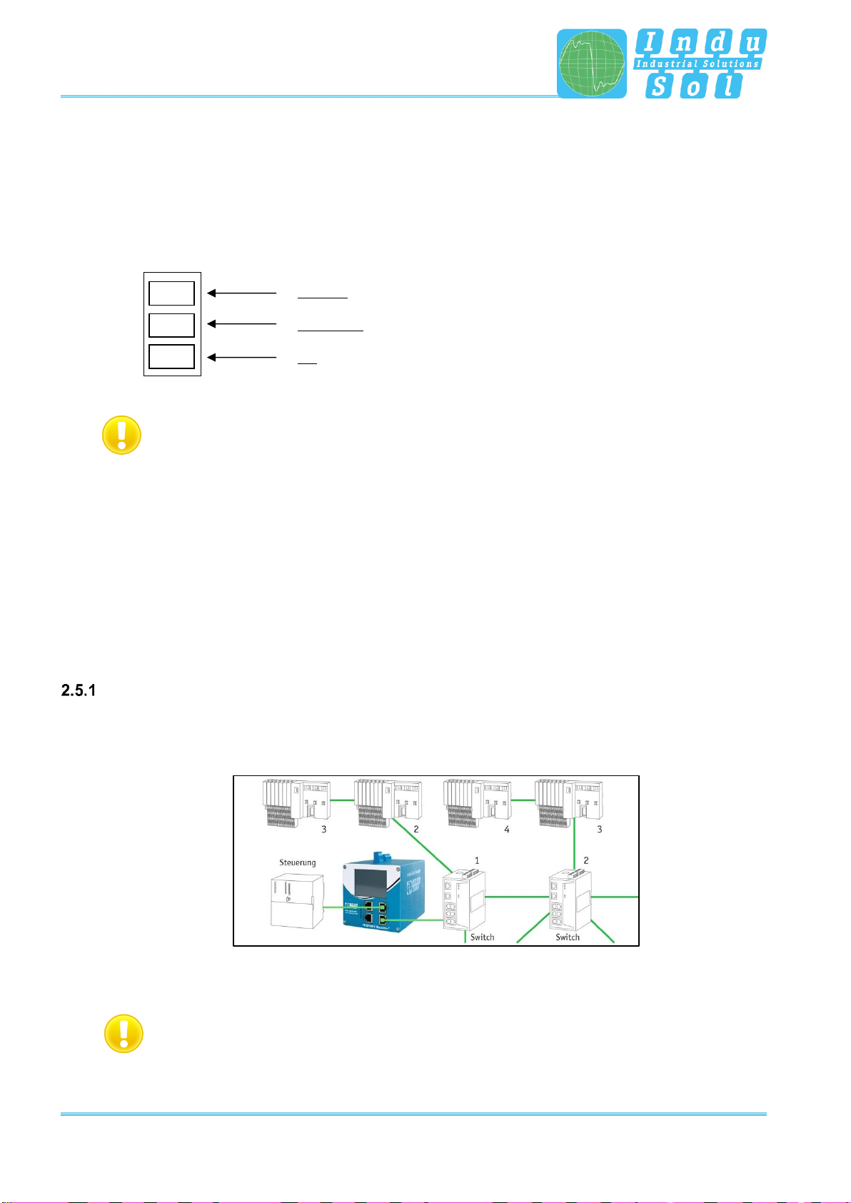
In conjunction with a feedback-free measurement point (e.g. PNMA II; art. no. 114090100), PN-INspektor®
NT can be connected to the PROFINET-system at any time without compromising ongoing system
operation. This can also be performed on a temporary basis if required. To do this, the PN-INspektor®NT
is hooked up to the M1 and M2 monitor sockets of the measurement point by means of two patch cables.
Figure 5: PN-INspektor®NT connection via PNMA II
2.6 Web interface
The LAN connections X2 and X3 of the web interface constitute the link to the PN-INspektor® NT. This
involves 10Base-T/1000Base-T RJ45 interfaces. A standard Ethernet cable is used as a connection cable
to a PC/ laptop (not included in the scope of supply).
A Web-server function is integrated for access to the device and can be opened with an appropriate
standard browser (e.g. Microsoft Internet Explorer from version 11 or Mozilla Firefox from version 45;
JavaScript must be activated). You can reach the device’s user interface by entering the IP address of the
PN-INspektor® NT in the browser’s command line.
Caution: To display the website correctly, the following ports must be enabled in firewalls,
gateways and routers: TCP/80 (http) and TCP/443 (https).
The PROFINET-INspektor® NT is supplied with the following factory-set network configuration:
PASSIVE –X2
ACTIVE –X3
IP address:
192.168.212.212
192.168.213.212
Subnet mask:
255.255.255.0
255.255.255.0

Installation
PROFINET-INspektor®NT - User Manual 15
Both the evaluation of internally recorded data and the parametrisation of the device are possible through
the PASSIVE and ACTIVE connection sockets. These are two independent network access. Additional to
the web access the active web interface can send requests to the PROFINET Network. For this it is
necessary to start a "Device scan" in the Device overview. This is used to retrieve and store information
such as the name, IP address and network topology for the respective device.
The active port must be configured to a free IP address from the PROFINET system to be scanned (see
section 3.5.1.5 Network) and integrated into the network (e.g. via a free switch port).
2.7 Signal inputs and outputs
The 6-pole connector terminal block (X5) at the top of the device is assigned as follows:
X5
Output:
- Potential-free switch contact (relay)
- Opener
Power supply Potential-free switch contact
max. 30V DC; max. 1A
3 inputs:
- Max. 24V DC ±20%
- Inactive < 3V
- Active > 10V
- Maximum current 0.15 mA
- Galvanically isolated
GND:
- Input earth potential
3
1
2
GND
OUT
OUT
Installation
PROFINET-INspektor®NT - User Manual 16
Input 1: Alarm acknowledgement (Web interface + switch contact)
Input 2: Alarm acknowledgement (switch contact)
Input 3: Alarm deactivation
Additional functions can be configured via the Web interface (see point 3.5.1.7 Digital Input)
2.8 Display screen
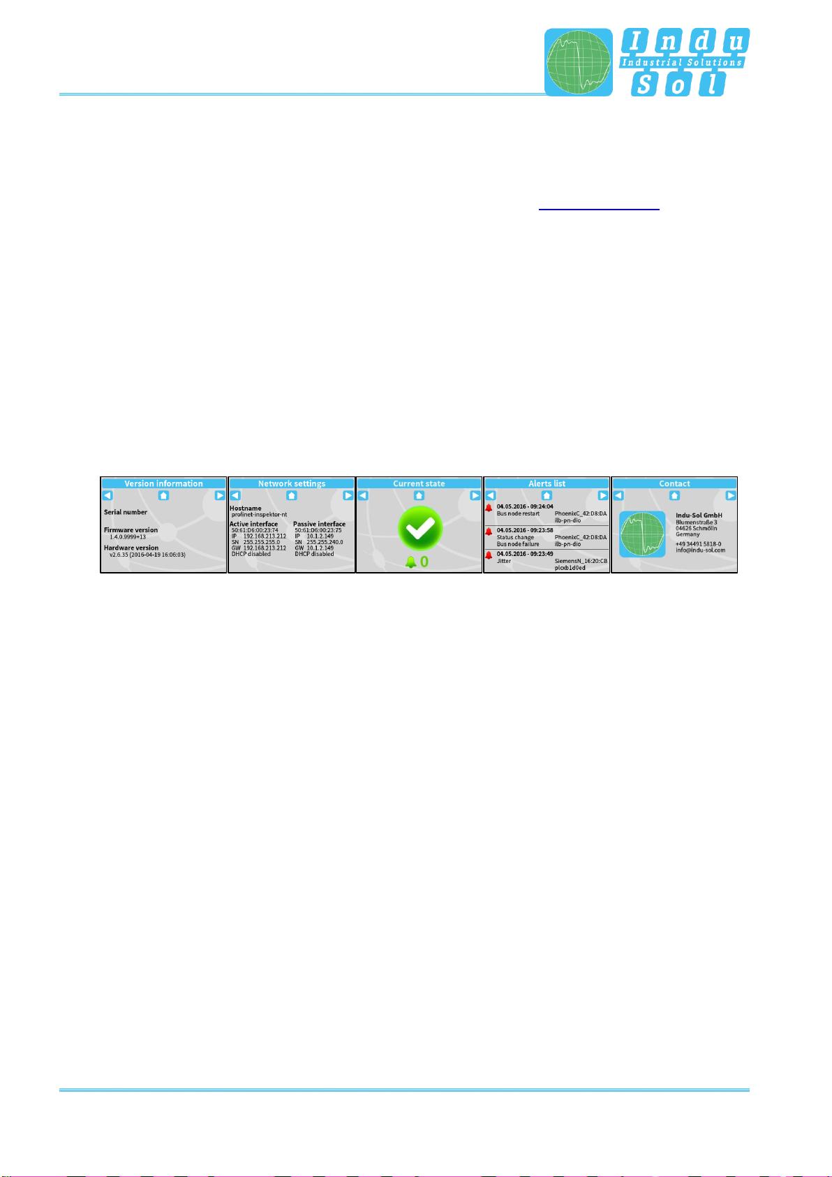
After connecting the power supply, the display conveys the system start-up of the PN-INspektor®NT.
After successful system start-up, the current state of the PROFINET network is always displayed on the
Home screen. You can scroll between the menu items with the arrow keys on both sides. The Home key
takes you directly to the Home screen.
The pending alarms are acknowledged by longer pressing (> 5 s) on the status symbol.
Figure 6: Touch-Screen menu

Web interface and selection functions
PROFINET-INspektor®NT - User Manual 17
3 Web interface and selection functions
To access the Web interface, and thus the recorded data of the PN-INspektor®NT, use an Internet browser
and enter the IP address (PASSIVE: 192.168.212.212; ACTIVE: 192.168.213.212) of the device to open
the web interface.
The following icons were used in the Web interface for a simple overview of the individual statuses of the
network and devices:
No faults: PROFINET communication is working without any problems.
Warning: A communication fault or a diagnostic message has appeared
in the network, or originated from a device, and this fault or message has
not yet led to system failure. The sources of these events should be
localised and resolved.
Fault: A critical fault has appeared in the network, or originated from a
device, and this fault leads to system failure. It is urgently necessary to
resolve the fault.
The bus communication in the network has failed or cannot be detected
by the PN-INspektor®NT (serious fault in the network) or the device is no
longer communicating or is not in the network.
Web interface and selection functions
PROFINET-INspektor®NT - User Manual 18
3.1 Homepage
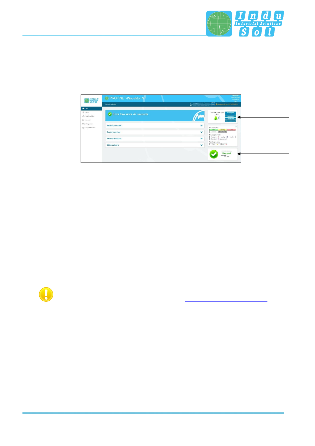
The homepage provides a complete overview of the status of the connected PROFINET system since the
start since the start of the current measurement.
If there are no entries here, the system is working stably and there are no urgent actions required.
Figure 7: Complete overview
There are additional helpful functions for obtaining more detailed information on the state of the network.
These can be accessed via drop-down menus or the Alarm Overview.
Specifying the time period, with a corresponding display of device information, is possible in the sub-menus
of the homepage. The relevant period of evaluation can be selected by switching the time window between
“current”, “last minute” and “history”. The “current” setting always displays the node condition (live list) at
that particular moment, and the “last minute” option shows the device information over the course of the
previous minute. With the “history” pre-selection, all data is displayed since the beginning of the recording
or the last time the “Delete data” or “New measurement” function was commanded. You can use these
different time references to determine whether PROFINET faults are occurring occasionally or permanently.
To adapt the user language of the web interface, it is possible to select the language by means of a mouse
over function on the "Language" item.
Language switching only affects the user interface. The settings for the display and the log text are
made by changing the system language (see section 3.5.1.4 Time and language settings).
Alarm overview
Timeline

Web interface and selection functions
PROFINET-INspektor®NT - User Manual 19
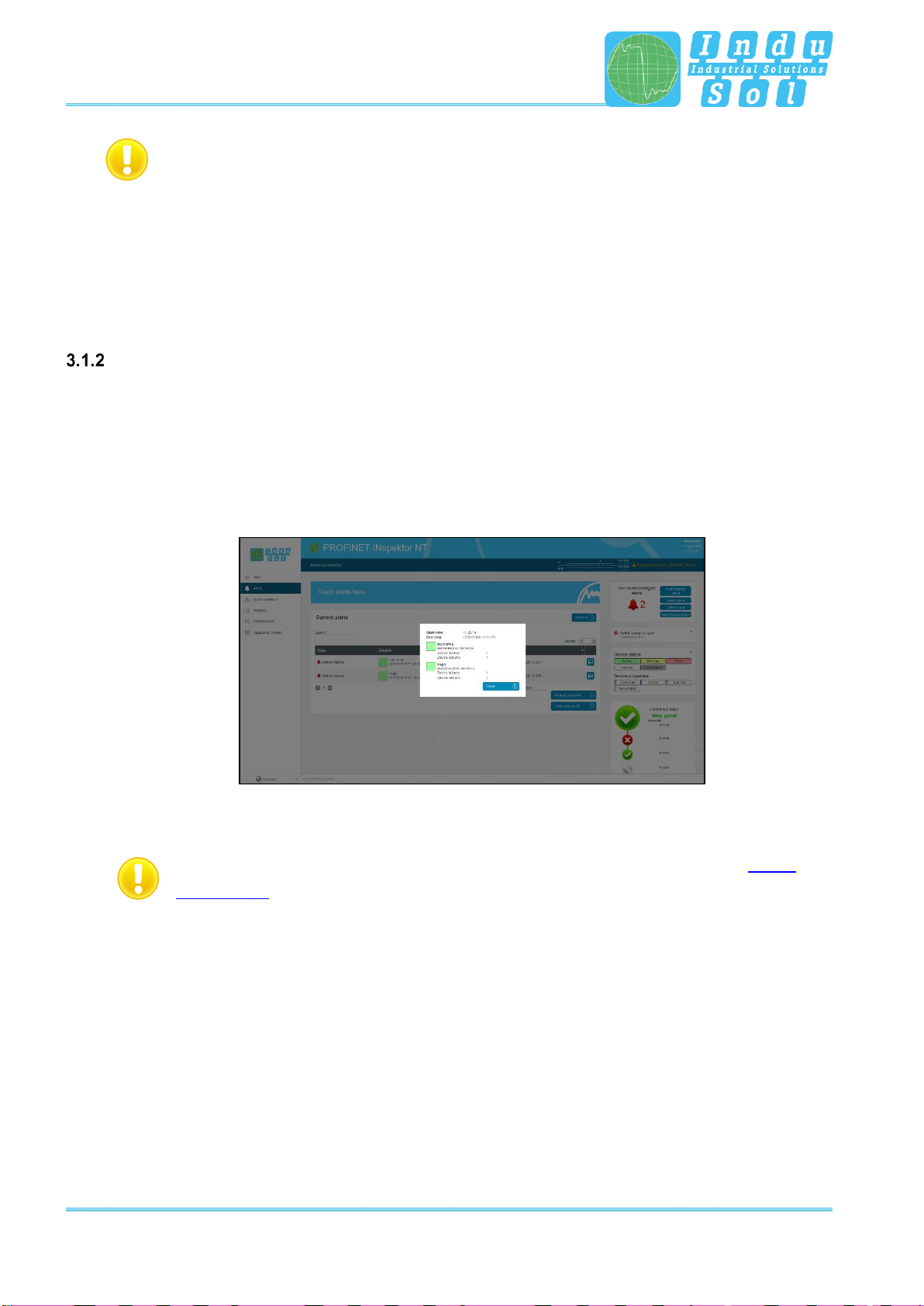
If errors occur during the overrun period, the relevant error trigger is triggered. This leads to entries in the alarm
overview, the timeline and the alarm list.
Figure 8: General overview in case of error
If the switching contact is activated at this time (see section 3.5.2.3 Triggers & alarms, factory setting: On), the
alarm signalling contact is switched on at the same time (contact opens) and the entry "Switching contact is
open" with the corresponding time stamp is displayed in the hint field.
In addition, changes made to the basic settings in the "Device status" menu (see section 3.5.2.2. Device status)
are indicated by the message "Status Settings have been changed" and in the "Triggers & Alarms" menu (see
section 3.5.2.3 Triggers & Alerts) by the display "Alarm Settings have been changed".
Alarm overview
In the alarm overview the number of unacknowledged alarms are indicated to you. The entries in the alarm
list are opened automatically with a mouse click on the alarm bell.
You can also perform the following functions in this window:
Acknowledge alarms: Unacknowledged alarms are acknowledged, but the entries stay in the alarm list.
The switch contact for the alarm is reset.
Delete alarms: All entries in the alarm list, including snapshots, are deleted.
Delete data: All previously recorded data is reset and the network analysis is restarted. The
device information (IP address, PN name) and configured settings are retained.
New measurement: This item is to be applied in the event of alternating use in different PROFINET
systems. By selecting this function, all previous entries including the node list are
deleted, and the network analysis is restarted. Any configuration settings made
are retained.
Hints
Web interface and selection functions
PROFINET-INspektor®NT - User Manual 20
Hint:
By regenerating the participant list, it is necessary to select the automatic deactivation
of new participants again, if desired. Settings for the configuration of monitored
connections can also be reset by pressing an optional selection field with the start of a
new measurement. Otherwise, the previously selected connections will continue to be
monitored.
Timeline
The timeline offers you a compact visual overview of the state of the network over the course of time. If
different network statuses are analysed within the course of the monitoring period, the point in time when
the respective status change started is presented as a new node (maximum 50 entries). Detailed
information accumulated within this time frame can be accessed by selecting one such node. The minimum
time period for a status change (new nodes) is one minute.
Figure 9: Timeline entry
The individual status changes can be adjusted for each node separately (See point 3.5.2.2
Device status) in order to adapt the display to the plant conditions.
Table of contents
Other Indu-Sol Diagnostic Equipment manuals


