Movu Argos User manual
Argos Quick Guide
Note: The quick guide only provides overview and tips for operation. For comprehensive instructions, please refer
to ARGOS user manual.
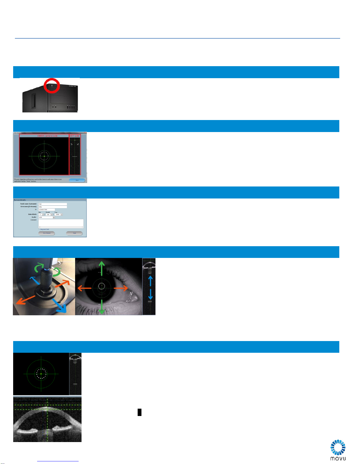
Powering On
To turn on Argos, simply press the top square PC power button to power Argos, PC, and
monitor
If the system was not shut down properly, you may see an option to use repair or restore
mode, but always select NORMAL mode. If Windows does not load, press and hold power
button until systems shuts down, then restart the system in normal mode.
Calibration
Calibration is prompted on every launch of the Argos program.
Calibration consists of two steps Referencing and Calibration
1. Referencing (NO TOOL): make sure nothing is in front of the system and press
NEXT, no calibration tool used in this step
2. Calibration (USE TOOL): Insert Calibration tool into forehead rest. Align yellow
crosshair to center of ring and specular reflections within the horizontal green markers
Input
Input allows selection of patient from database (left side) or entry of new patient (right side)
To enter a new patient, click NEW patient, do not overwrite a previous patient.
After choosing or creating a patient, clicking next will advance the software to the
measurement process.
Alignment
Adjust height using dial under chinrest for vertical movement.
Bring patient eye level to mark on chinrest frame
To move coarsely:
Slide the stage left to right for lateral movement, forward and
back for depth movement.
The joystick can be rotated for height adjustment
To fine tune:
Use the joystick for height fine tuning: clockwise moves LED ring
and the yellow x up; counterclockwise moves the yellow x down
Use the joystick for fine lateral tuning side to side
Use the stage for fine tuning of the depth of the OCT image
Measure
Select OD/OS and eye type (phakic, pseudophakic or aphakic) to begin measurement.
Instruct the patient into the correct position. OD is indicated in blue throughout the system,
OS is in gray. Use the vertical chin adjustment knob to bring the patient eye level to the
frame marker. Make sure the forehead rests against the forehead bar.
Instruct patient to look directly into center LED*
Align system for measurement.
Push/Pull focus eye in camera image. Center LED ring within green circle to begin
tracking
Align yellow Xinside the inner circle
Align the cornea into the horizontal dashed lines with push/pull
Press joystick button to take measurements
Repeat measurements at least 3 times per eye

Measurement Tips
It is recommended to measure always measure both eyes. Argos program will check for accuracy using deviation
between left and right eye measurements
Patients may have different left and right eye types
ERV Mode
If the retina is obscured, Enhanced Retinal Visualization (ERV) mode shifts coherence
function towards the retinal region. ERV mode can provide additional confidence in axial
length measurement.
ERV only calculates Axial Length. Select ERV mode after taking a normal measurement to
acquire other parameters
A mechanical sounds is audible indicating this mode is active
Align the apex of the cornea between the target markers before taking measurement
Non-fixating eye
Patients with thick cataracts may have difficulty seeing. Dim the
lights or instruct to look straight forward with the other eye.
Place a finger or sticker directly in front of the patient’s other
eye on the top edge of Argos unit. Instruct patient to fixate vision
on fingertip.
The edge is vertically aligned with the laser beam.
Analyze
Check all measurements and images for correct boundary detection
Manual adjustment: If necessary, adjust the line marker to align to the correct boundary. It
will be compared to all three images to make sure standard deviation is within target
accuracy.
Make sure to select only plausible measurements after review.
Tilted Eye Error
Tilted eyes will cause retina to appear differently on scan and image. Significantly tilted eyes
will have pronounced ILM due to offset of scanning beam.
Conduct a visual check for tilted image on the side view. Unselect images with tilt.
Tilted images may result in incorrect length measurements.
Summary
Summary window is presented as a table with the measured parameters
AL/ACD/K can be edited with values from other devices (Ultrasound/Keratometer)
Warning notation:
Significant difference between OD and OS
Results are out of standard deviation/manually edited
IOL Power
IOL Power calculation
Select a Surgeon and target refraction
Select IOL model and IOL formula up to four combinations
Toric calculation (see detailed instruction in user manual)
Select Toric Planner
Input SIA and Incision Angle with target refraction
Select Barrett Toric or General Toric calculator
Table of contents


