TELEMED UAB ClarUs User manual

TELEMED ClarUs User Guide, REV 4.0 2013.12.04
1
ClarUs
ClarUs EXT-1M
Ultrasound Diagnostic System
USER GUIDE

TELEMED ClarUs User Guide, REV 4.0 2013.12.04
2
Manufactured by
TELEMED UAB
Dariaus ir Gireno str. 42
Vilnius LT-02189
Lithuania
Telephones: (+370-5) 2106272 (+370-5) 2106273
Fax: (+370-5) 2306733
Internet: http://www.telemed.lt
E-Mail: info@telemed.lt
NOTE: Non-TELEMED product names may be trademarks or registered trademarks
of their respective owners.

TELEMED ClarUs User Guide, REV 4.0 2013.12.04
3
1.INTRODUCTION 5
1.1. About the system / Intended use 5
1.2. Delivery set 7
1.3. About the system software 7
1.4. Technical Specification 7
2.SAFETY 12
2.1. Electrical safety 12
2.2. Equipment protection 13
2.3. Biological safety 13
2.4. Ultrasound exposure and ALARA principle 14
2.5. Cyber security 15
2.6. Accuracy Measures 15
3.LABELING 17
4.SYSTEM OVERVIEW 18
4.1. Principle of operation 18
4.2. Components & Modifications 18
4.2.1. Basic unit/Beamformer 18
4.2.2. Probe Unit 18
4.2.3 ClarUs 19
4.2.4 ClarUs EXT-1M 19
4.3. Connection and Indication ClarUs 20
4.4. Peripherals/Compatibility 22
5.INSTALLATION WARNINGS 23
5.1. Getting started with ClarUs 24
5.2. Status Indicator 24
5.3. Ultrasound Scanner Monitor utillity 24
5.4. Windows configuring 26
6.TROUBLESHOOTING 27
6.1. FAQ 27
6.2. Fuses locations (ClarUs) 27
6.3. Contact with technical support service 28
7.WARRANTY AND SERVICE INFORMATION 29
7.1. Warranty 29
7.2. Warranty Shipments and Returns 29
7.3. Service Contract 29
8.MAINTENANCE 30
8.1. General cleaning 30
8.2. Inspecting the System 30
8.3. Probe maintenance and disinfection 30
8.3.1 Chemicals that Damage Transducers: 31
8.3.2 Recommended Procedures for Probe Processing 31

TELEMED ClarUs User Guide, REV 4.0 2013.12.04
4
8.3.3 General Cleansing for Transducers Used in Non-Invasive Procedures.......31
8.3.4 Cleansing and Disinfection of Transducers Used in Endocavity
Procedures 32
8.4. System accuracy / performance verification 32
9.TRANSPORTATION, STORAGE AND UTILIZATION 33
9.1. Transportation and storage 33
9.2. Utilization 33
10. ............DECLARATION OF CONFORMITY 34
APPENDIX
1.Guidelines for the safe use of diagnostic ultrasound
2.Vigilance system
3. Returned product form

TELEMED ClarUs User Guide, REV 4.0 2013.12.04
5
1. INTRODUCTION
CAUTION:
United States federal law restricts this device to be used by, or on the
order of, a licensed physician.
Dear customer,
Our ClarUs system is intended for multipurpose ultrasound examinations, based on
electronic linear and convex scanning.
It is an ideal budget solution for hospitals, specialized diagnostic centers and
public and private clinics.
Our new class of PC-based compact ultrasound scanners now features:
beamformer with multi-frequency probes support;
Scan-converter free architecture;
Industry standard tZIF-260 (Zero Insertion Force) probe connector;
Digitally controlled acoustic power;
Light weight, true mobility, flexible architecture.
Here in the User Guide you can find information about ClarUs and safety and
maintenance information.
Echo Wave II Software Operation Manual contains a description of the
controls.
1.1. About the system / Intended use
ClarUs system is intended to be used for applications in fetal, abdominal,
small organ (thyroid and breast), cardiac, peripheral vascular, musculo-skeletal
(conventional) and needle guidance. It is possible to provide diagnostic information
outside of an imaging lab, including at the bedside systems, for navigated medical
applications and in operating rooms/critical care units.
ClarUs ultrasound systems provide many different scanning technologies: B,
B+B, 4B, B+M, M, CFM, PDI, DPDI, PWD, B+PWD (Duplex),
B+CFM/PDI/DPDI+PWD (Triplex), HPRF, automatic image optimization,etc. Echo
images can be either full size or zoomed.
Unlike ordinary ultrasound devices, this scanner is based on modern digital
technologies. PC application enables many powerful innovative features such as:
user friendly, easy-to-use intuitive graphic user interface;
echo image storage on hard disk or other devices;
storage of a sequence of full size echo images (cineloop) with the opportunity
to save it in video file format;
image and cineloop file formats enables using other applications for viewing
stored data;
using a variety of peripheral devices;
direct echo image and video e-mail sending with one click.
A variety of available ultrasound probes provides many different applications
for examinations in therapy, obstetrics, gynecology, urology, pediatrics, oncology and
other areas.

TELEMED ClarUs User Guide, REV 4.0 2013.12.04
6
Common view of ClarUs shown below.
Figure 1
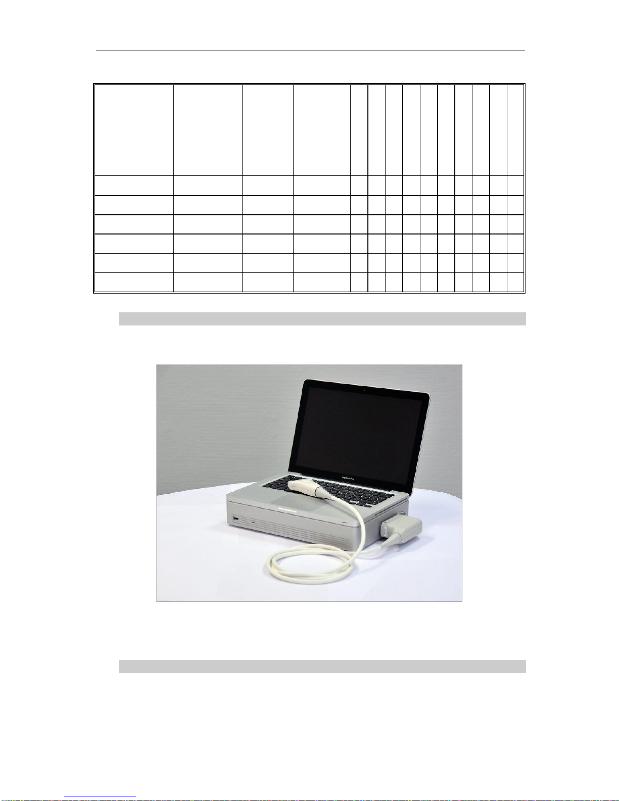
Common view of ClarUs EXT-1M shown below.
Figure 2

TELEMED ClarUs User Guide, REV 4.0 2013.12.04
7
1.2. Delivery set
ClarUs
ClarUs EXT-1M
Basic Unit
●
Beamformer
●
Operation manual
●
●
User guide
●
●
Software and manuals
(CD-ROM)
●
●
Power Cable
●
Standard USB cable
●
Power supply (medical)
●
Windows OS installation CD
●
MacBook Pro manual
●
Mac OS X Install DVD
●
Application Install DVD
●
Ultrasound probe
Types and quantity defined by customer
1.3. About the system software
Your diagnostic system contains Echo Wave II software to control its
operation. TELEMED provides the latest Echo Wave II software version and drivers
package together with your system. In the software the unique technologies making
the intellectual property of TELEMED company are used. Latest software versions
can be downloaded directly on the Internet from http://www.telemed.lt .
1.4. Technical Specification
Table 1 contains technical specifications of ClarUs:
Table 1
IMAGING MODES
B
B+B
4B
B+M
M
Color Doppler (CFM)
Power Doppler (PDI)
Directional Power Doppler (DPDI)
Pulse Wave Doppler (PWD)
B+PWD (Duplex)
B+CFM/PDI/DPDI+PWD (Triplex)
ULTRASOUND IMAGING

TELEMED ClarUs User Guide, REV 4.0 2013.12.04
8
ultrasound image size: automatically
adjustable to screen resolution
gray scale: 256
color scale: 256
full motion and full size real-time
ultrasound imaging, up to 120 fps
(depends on selected scan depth,
scan angle, focus mode, High Line
Density setting, computer speed)
cineloop recording/play: several
thousands frames (depends on
computer memory size and scan
mode)
zoom mode: from 60% to 600% in all
modes (Scan, Freeze, B, B+B, 4B,
Doppler modes, M-zoom, cineloop
and etc)
viewing area variable for frame rate
maximizing: 6 steps
"FREEZE" mode
SCANNING METHOD
Electronic linear
Electronic convex
Electronic micro-convex
COLOR DOPPLER
PRF variable: 0.5-9 kHz
wall filter settings: 3 steps
(5%, %10%, 15% PRF)
gain control: 50 dB
angle steering for linear probes: ±10°
real-time spatial filter: 3 values
CFM palette: 10 maps
B/Color priority control
color threshold control
CFM baseline control
Doppler frequency selection:
2 frequencies / each probe
color frame averaging: 8 values
PULSED WAVE DOPPLER
PRF variable:
0.3-10 kHz
wall filter settings:
16 steps (2.5%-20% PRF)
gain control: 50 dB
angle steering for linear probes: ±10°
single click auto adjustment:
baseline, measurements, invert
stereo sound: volume control
PWD palette: 12 maps
Doppler frequency selection:
2 frequencies / each probe
DEPTH SELECTION
2 –30 cm (depth range depends on probe type and scanner model)
PROBES
probes:
ofrom 2 MHz to 12 MHz
oMulti-frequency
Automatic probe recognition
FOCUSING
Digital transmit focusing
Yes
Multi focus mode
Transmit/receive focusing, max 4 points
Programmable focus area presets
Dynamic focus mode
Transmit variable focus, 8 points
Dynamic receive focus, 8 zones
SIGNAL PROCESSING

TELEMED ClarUs User Guide, REV 4.0 2013.12.04
9
High Line Density scan mode for better resolution
TGC Control, 5 sliders 40 dB
dynamic range: 120 dB, 8 values
overall gain control
M - mode sweep speed control
acoustic power control
variable frame averaging
brightness, contrast
advanced gamma control: 8 fixed curves, 8 user defined (custom)
scan direction, rotation, up-down controls
negative / positive control
bi-linear interpolation
echo enhancement control
noise rejection function
speckle reduction function (optional)
FUNCTIONS
General Measurements
and Calculations
Mouse / trackball / keyboard operation of multiple calipers
B-mode: Distance / Length / Area / Circumference /
Volume / Angle / Stenosis % / A/B Ratio
M-mode: Distance / Time / Velocity / Heart Rate /
Stenosis % / A/B Ratio
Human Measurements
and Calculations
Packages
General calculations package
Obstetrics / Gynecology (OB / GYN) calculations package
Gynecology (GYN)
Abdominal exam measurements and calculations
Urology
Endocrinology
Vascular exam measurements and calculations
Cardiology
Veterinary Calculations
Packages
Obstetrics:
Canine / Feline / Ovine / Bovine / Equine / Llama / Goat
Animal Cardiology
User Interface
The set of predefined skin schemes for user interface
User-friendly pop-up menus and dialogue boxes
Unlimited programmable presets for clinically specific
imaging
Image comment / save / recall browsing
Anatomical Icons with probe position indicator
Indication
Power LED indicator of system status
Image and video save /
load
JPG BMP PNG TIF AVI DCM DCM(JPG) TVD TPD
Cineloop
Recording up to 2048 frames to memory
Play / Pause / Stop / Frame selection
Saving ultrasound video file to disk
Loading ultrasound video file from disk
Printing
System printer

TELEMED ClarUs User Guide, REV 4.0 2013.12.04
10
Internet
Direct e-mail sending function
with image or video attachment
TV output
Standard TV output using computer's display adapter
(option)
ULTRASOUND SOFTWARE
Drivers
TELEMED Drivers Package
Software
Echo Wave II software (B/W + Doppler modes)
Plug-Ins
ClearView plug-in (optional)
3DView plug-in (optional)
PanoView plug-in (optional)
Library for programmers
SDK documentation / sample code
(available by agreement)
DIMENSIONS AND WEIGHT
Dimensions W x D x H
mm
335 x 230 x 75 ClarUs
62 x 210 x 165 ClarUs EXT-1M
Weight, kg
4.5 ClarUs
1.6 ClarUs EXT-1M
POWER ClarUs
100-240 VAC
47-63 Hz
100VA
Built-in 60 watt-hour
lithium-polymer battery
battery life: 60 min (depending on scan mode)
battery charging time: up to 2 hours
POWER ClarUs EXT-1M
12 VDC
2.5 A
External AC medical grade power supply (100-240 VAC,
50-60 Hz)
SAFETY
Electromechanical safety
IEC601-1-2 Medical electrical equipment part 1: General
requirements for safety.
Class I Type BF applied part
EMC/EMI standards
European Norm EN 55011:1998 (CISPR 11:1999)
Industrial, scientific and medical (ISM) radio-frequency
equipment. Radio disturbance characteristics. Limits and
methods of measurement.
Ultrasound exposure
CEI/IEC 61157:1992, International Electro technical
Commission, Requirements for The Declaration of the
Acoustic Output of Medical Diagnostic Ultrasonic
Equipment.
AIUM/NEMA: Standard for real-time display of thermal
and mechanical acoustic output indices on diagnostic

TELEMED ClarUs User Guide, REV 4.0 2013.12.04
11
ultrasound equipment.1992.
OPERATIONAL ENVIRONMENT
Nominal operational
environment
Environment temperature : 10 - 40 °C
Relative humidity not to exceed: 85 %
Atmospheric pressure: 70 - 106 kPa

TELEMED ClarUs User Guide, REV 4.0 2013.12.04
12
2. SAFETY
CAUTION :
Please read this information before using the diagnostic system. It
applies to the ultrasound system, transducers, accessories and
peripherals.
2.1. Electrical safety
This system complies with the applicable medical equipment requirements and
meets IEC601-1, Class I Type BF safety requirements.
NOTE :
All persons connecting computer equipment as medical appliance
are configuring a medical system and are therefore responsible for
ensuring that the system complies with IEC 601-1-1. The
achievement of PC compliance with the IEC 601-1 requirements is
based on electrical safety. A standard PC power supply is almost
certain to not comply with IEC 601-1 electrical requirements in
several ways , e.g. leakage current requirements, dielectric strength
requirements.
One possible solution is powering the PC (and computer monitor)
via a 1:1 medical insulation transformer, which has been designed
to meet IEC 60601-1 requirements. The best solution is a fully IEC
601-1 certified PC or a battery operated portable PC and wireless
peripheral devices.
All systems (including monitors and other connected parts) must
be configured to comply with IEC 601-1-1. If in any doubt please
contact the technical service department of your local
representative.
Note that regardless of the above stipulations all personal
computers used should be approved regarding the IT (information
technology) safety standards for electrical ) equipment (such as.
IEC 60950 or equivalent) .
The electrical specification is shown below and can be found labelled on the
rear panel of scanner.
To avoid electrical shock only use the supplied power cables and connect it to
a properly earthed power socket. Do not use a three pin - two pin adapter. This
defeats the whole purpose of earthing for safety reasons. Systems should be
operated within the voltage limits.
WARNING:
In the event of detecting a discrepancy regarding patient safety
requirements (occurrence or probability of risk) you must to inform
the local dealer and the manufacturer immediately (for single
European customers –inform the EC representative labeled on the
rear panel).

TELEMED ClarUs User Guide, REV 4.0 2013.12.04
13
If the ultrasound scanner will be moved or left unused for a long period of time
without being switched on it is recommended that it be disconnected from power
supply. If a scanner is to be switched on, do not interrupt this while operating the
system and while the ultrasound software is being loaded. The time for this operation
is approximately 1 min.
To avoid the risk of electrical shock and fire hazard:
before using the probe, inspect the probe face, housing, and cable and do not
use the probe if the probe or the cable is damaged;
always disconnect the AC power supply from the system before cleaning the
system;
do not use any probe that has been immersed beyond the specified cleaning
or disinfection level;
inspect the power supply, AC power supply cable and electrical plug on a
regular basis to ensure they are not damaged;
only use accessories and peripherals recommended by TELEMED.
WARNING:
To avoid the risk of electrical shock do not open the cover of
device/blocks. There are no parts that you can repair yourself. In
case of dificulties please contact the TELEMED service department
or your nearest local authorized distributor.
2.2. Equipment protection
To protect your ultrasound system, transducer and accessories, please follow
these precautions:
excessive bending or twisting of electrical cables can cause a failure or
intermittent operation;
incorrect cleaning or disinfecting of any system part can cause permanent
damage, for cleaning and disinfecting instructions see the relevant chapter
below;
do not use solvents such as thinners/benzene or abrasive cleaners on any
parts of the system;
do not spill liquids on the system;
incorrect assembly or configuration and using an incorrect power source may
damage the system.
WARNING:
Ultrasound probes can easily be damaged by incorrect handling!
Failure to follow these precautions can result in serious injury and
equipment damage!
2.3. Biological safety
Observe the following precautions related to biological safety:
do not use the system if it displays erratic or inconsistent behavior;
TELEMED ClarUs User Guide, REV 4.0 2013.12.04
14
interuptions to the scanning sequence are signs of hardware failure that must
be corrected before use;
do not use the system if it displays artifacts on the LCD screen, either within
the clinical image or on the area outside it;
artifacts are indications of hardware and/or software errors that must be
corrected before use;
The hardware limits the maximum probe surface temperature
to a maximum of 43°C even in the event of a device malfunction.
2.4. Ultrasound exposure and ALARA principle
Perform ultrasound procedures prudently, use the ALARA (As low As Reasonably
Achievable) principle (see APPENDIX: 1.Guidelines for the safe use of diagnostic
ultrasound).
The interactive system features or user controls that may affect the acoustic output
are:
acoustic output control,
transmit frequency;
scanning depth;
transmit focal length;
scanning angle.
Acoustic output also depends on the imaging mode selected. The choice of mode (B-
Mode, M-Mode, B+M-Mode) determines whether the ultrasound beam is stationary or
in motion. B+M-Mode has the highest acoustic output.
The default output level is factory calibrated and is based on device settings that
yield an optimum image for the type of patient examination and do not exceed the
following FDA recommended limits.
This default level is set:
when the system is first turned on;
when the probe is first turned on.
It is highly recommended to set the default level:
when changing from one exam category to another;
when changing from one application to another;
when changing from one probe to another;
when a new patient is entered.
Once an optimal image is achieved, the need for increasing acoustic output or
prolonging the exposure cannot be justified. Watch the POWER level (on-screen
display) permanently. Whenever possible, controls and system features should be
used to optimize the image before increasing the acoustic output level. Follow the
ALARA principle during all patient examinations.
The ClarUs employs the ALARA principle in configuring factory defaults.
CAUTION:
Probe sheaths/covers may contain talc and natural rubber latex.
Examine the package labeling to confirm any latex content. We
strongly recommend that healthcare professionals identify their
latex-sensitive patients and refer to the FDA regulations.
NOTE: TELEMED diagnostic ultrasound systems and probes do not
contain natural rubber latex that comes into contact with humans.

TELEMED ClarUs User Guide, REV 4.0 2013.12.04
15
Ultrasound waves used in diagnostic system have frequencies ranging from
3,5 MHz to 7,5 MHz. Sound waves with such frequencies are weakened in the air, so
can be measured for example in water. Ultrasound waves sent by a converter are so
weak (medium intensity less than 100mW/cm²), that according to International
Electro technical Commission (IEC 1157) standards (well within AIUM/NEMA
standards) they do not have any impact on patient health (however any unnecessary
exposure should be avoided).
Detailed information is found in
APPENDIX: 1. Guidelines for the safe use of diagnostic ultrasound.
Acoustic output tables for global maximum values for all systems and
transducer combinations (3 samples of each type of probe) are included
APPENDIX: 2. Acoustic output.
2.5. Cyber security
Vulnerabilities in cyber security may represent a risk to the safe and effective operation
of networked medical devices. Store only relevant and necessary software on working
computers.
Network administrators in healthcare organizations and information technology
providers should assure an adequate degree of protection from threats such as viruses
and worms to avoid the risk of any unauthorized access to the network or the medical
device/database.
2.6. Accuracy Measures
CAUTION :
Gas ultrasound contrast agents are used during echocardiography
to enhance a cardiac image but may cause side effects (cardiac
rhythm disturbances during perfusion studies).
Because of this, see the package labelling / insert about the risks of
both cardiopulmonary and hypersensitivity reactions (unstable
status). It is recommended to monitor vital signs, cardiac rhythm
and oxygen saturation, and to have resuscitation equipment and
trained personnel readily available.
Additional Information:
FDA MedWatch Safety Alert. Micro-bubble Contrast Agents
(marketed as Definity (Perflutren Lipid Microsphere) Injectable
Suspension and Optison (Perflutren Protein-Type A Microspheres
for Injection). October 12, 2007.
http://www.fda.gov/medwatch/safety/2007/safety07.htm#bubble
WARNING:
Clinical diagnostic errors may result from the incorrect use of
calculations. Review the referenced source of the stated formula or
method to become familiar with the intended uses and possible
are provided as a tool to assist the user and should not be
considered as an undisputed database when making a clinical

TELEMED ClarUs User Guide, REV 4.0 2013.12.04
16
The accuracy of measurements is determined not only by the TELEMED Echo
Wave II software but also by the proper use of medical protocols.
Distance and area/circumference measurements are displayed to 0.1 mm.
The following general assumptions can be made about the accuracy of any
ultrasound system:
oVelocity of sound is constant - 1540 m/s
oVelocity of sound uncertainty = 5%
oCaliper placement accuracy is one pixel (operator dependent)
oMeasurement accuracy is based on the root-mean-square combination of
all independent sources of error
oRMS errors are due to velocity of sound uncertainty, pixel error, and typical
transducer geometry
The chapter 4.7 Measurement accuracies of Echo Wave II Software Operation
Manual contains the tables of Measurement and Calculation accuracies.
diagnosis.

TELEMED ClarUs User Guide, REV 4.0 2013.12.04
17
3. LABELING
Table 2 describes the purpose and location of safety labels and other
important information provided on the equipment.
Table 2
LABEL/SYMBOL
DESCRIPTION
LOCATION
Identification and
Rating Plate
Manufacturer name and
address;
Model;
Serial number;
Electrical ratings.
Rear panel
Type/Class Label
Used to indicate the degree of safety
or protection
Rear panel (along
with rating plate label)
MAINS ON indicates the power on
position of the mains power switch
On the main power
switch, ClarUs
MAINS OFF indicates the power
disconnection from the mains
CE marking
Rear panel (rating
plate label)
Type BF Equipment (man symbol) IEC
878-02-03 indicates BF type equipment
which provides a particular degree of
protection against electric shocks,
particularly regarding allowable
LEAKAGE CURRENT and reliability of
the PROTECTIVE EARTH
CONNECTION if present.
External
(probe outlet)
The symbol for CAUTION highlights
the fact that there are specific
warnings or precautions associated
with the device
Rear panel (along
with rating plate label)
CONSULT INSTRUCTIONS FOR
USE demonstrates that symbols are
meant to support, not replace,
operating instructions.
Rear panel (along
with rating plate label)
The symbol indicating separate collection for
electrical and electronic equipment (Annex IV
of Directive 2002/96/EC)
Rear/bottom panel
USB connector. This label indicates USB
connector.
Rear panel
ClarUs EXT-1M
DC power input
Rear panel
ClarUs EXT-1M

TELEMED ClarUs User Guide, REV 4.0 2013.12.04
18
4. SYSTEM OVERVIEW
The ClarUs system handles the multi-element probes.
4.1. Principle of operation
The ultrasound diagnostic system is based on the effect of ultrasound wave
reflection from the tissue edges with different acoustic impedance levels. Ultrasound
waves sent out by the probe head are emitted into the patient’s body. Reflections
from the specific types of tissue and their external surface/edges cause partial
reflections of the propagating sound wave. The return echo comes back to the probe
head and after being detected and amplified is displayed on the monitor screen as a
pixel combination with various shades of brightness creating an ultrasound image.
4.2. Components & Modifications
4.2.1. Basic unit/Beamformer
Basic unit functions are:
excite electric pulses to fire the probe;
ultrasound echo signals pre-amplification;
compensation of the ultrasound attenuation due to travel depth;
re-ordering the receiving signal sequence and focusing by applying the
appropriate time delays;
shifting the center frequency of BPF (band pass filter) to follow the frequency
shift that occurs according to the travel depth;
the ultrasound signal compression by means of Log Amplifier, detection of the
echo signal envelope
4.2.2. Probe Unit
The probe unit is a piezoelectric transformer which provides the acoustical
pulse used to examine the medium and is used for both transmission and reception
(the transducer is used in pulse-echo mode). A voltage waveform is applied to the
transducer and then converted into an acoustic waveform (inverse piezoelectric
effect). An acoustic pulse is then partially transmitted and partially reflected by the
intervening soft tissues structures in the body. The reflected acoustic waveform is
received by the same transducer and is converted into a voltage waveform (direct
piezoelectric effect). The probe unit consists of piezoelectric elements. The probe
enclosure has a relief to affix the scanning direction.
TELEMED ClarUs User Guide, REV 4.0 2013.12.04
19
Type
Order Code
System
Frequencies,
MHz
Radius
mm
Field of
View /
Degree
mm
Abdominal
Cardiac
Obstetrics
Pediatrics
Small Parts
Transrectal
Transvaginal
Vascular
Veterinary
Biopsy Adaptor
MC10-5R10N
5.0-8.0
10
156
●
●
●
MCV9-5R10N
5.0-8.0
10
156
●
●
●
MC4-2R20N
2.0 - 4.0
20
104
●
●
C7-3R50N
3.0 - 7.0
50
70
●
●
●
C5-2R60N
2.0 - 5.0
65
59
●
●
●
●
●
L12-5L40N
5.0 - 12.0
-
39
●
●
●
●
●
4.2.3 ClarUs
ClarUs is an all-in-one modification combined beamformer and notebook
4.2.4 ClarUs EXT-1M
ClarUs EXT-1M is the beamformer to be connected to a PC through USB 2.0

TELEMED ClarUs User Guide, REV 4.0 2013.12.04
20
4.3. Connection and Indication ClarUs
Front view
Rear view
This manual suits for next models
1
Table of contents
Other TELEMED UAB Diagnostic Equipment manuals


