Softing TH LINK PROFINET User manual

© Copyright 2014 - 2016 Softing Industrial Automation GmbH
TH LINK PROFINET
Installation Manual
Version: EN-012017-2.00

The information contained in these instructions corresponds to the technical status at the time of printing of it and is passed on with the
best of our knowledge. The information in these instructions is in no event a basis for warranty claims or contractual agreements
concerning the described products, and may especially not be deemed as warranty concerning the quality and durability pursuant to Sec.
443 German Civil Code. We reserve the right to make any alterations or improvements to these instructions without prior notice. The
actual design of products may deviate from the information contained in the instructions if technical alterations and product improvements
so require.
It may not, in part or in its entirety, be reproduced, copied, or transferred into electronic media.
Disclaimer of liability
Softing Industrial Automation GmbH
Richard-Reitzner-Allee 6
85540 Haar / Germany
http://industrial.softing.com
The latest version of this manual is available in the Softing download area at: http://industrial.softing.com/en/downloads.html
+ 49 89 4 56 56-0
+ 49 89 4 56 56-488
info.automation@softing.com
support.aut[email protected]

Copyright 2016 Softing Industrial Automation GmbH 3
Table of Contents
Table of Contents
Chapter 1 ............................................................................................ 5
Introduction
...................................................................................................................... 5
1.1 About TH LINK
...................................................................................................................... 5
1.2 Intended Use
...................................................................................................................... 5
1.3 Before you connect TH LINK
...................................................................................................................... 6
1.4 Conventions used
...................................................................................................................... 7
1.5 Delivery scope
...................................................................................................................... 7
1.6 Document history
...................................................................................................................... 7
1.7 Configuration requirements
...................................................................................................................... 8
1.8 Network presettings
Chapter 2 ............................................................................................ 8
TH LINK design
...................................................................................................................... 8
2.1 Connections and display elements
...................................................................................................................... 9
2.2 Mounting
...................................................................................................................... 10
2.3 SD card
Chapter 3 ............................................................................................ 10
Start-up guideline
Chapter 4 ............................................................................................ 10
Mount/unmount device
...................................................................................................................... 10
4.1 Mount device
...................................................................................................................... 11
4.2 Unmount device
Chapter 5 ............................................................................................ 11
Connect to network
Chapter 6 ............................................................................................ 13
Connecting power supply and relay contact
Chapter 7 ............................................................................................ 13
Configuring the device in the network
...................................................................................................................... 14
7.1 Connection in a network with DHCP server (Dynamic Host Configuration
Protocol)
...................................................................................................................... 14
7.2 Connection in a network with manual IP address assignment
...................................................................................................................... 14
7.3 Setting new IP and network address
...................................................................................................................... 16
7.4 Check the connection to the device
Chapter 8 ............................................................................................ 16
Network overview
Chapter 9 ............................................................................................ 17
Login/Logout
...................................................................................................................... 17
9.1 Login
...................................................................................................................... 17
9.2 Logout
Chapter 10 ............................................................................................ 18
Settings pages
...................................................................................................................... 18
10.1 TH LINK
.................................................................................................................. 19
User administration - change password10.1.1
.................................................................................................................. 19
TH LINK description10.1.2

Copyright 2016 Softing Industrial Automation GmbH
Table of Contents
4
.................................................................................................................. 19
Network configuration10.1.3
...................................................................................................................... 19
10.2 TH SCOPE
.................................................................................................................. 20
Measurement10.2.1
.................................................................................................................. 20
Alert10.2.2
.................................................................................................................. 21
Parameter distribution10.2.3
..................................................................................................... 21
Set parameter provider
10.2.3.1
..................................................................................................... 21
Apply parameters
10.2.3.2
..................................................................................................... 22
Parameters
10.2.3.3
Chapter 11 ............................................................................................ 22
Firmware update
Chapter 12 ............................................................................................ 23
Blacklist
Chapter 13 ............................................................................................ 24
Troubleshooting
Chapter 14 ............................................................................................ 24
Technical Data

Chapter 1 - Introduction
Copyright 2016 Softing Industrial Automation GmbH 5
1Introduction
1.1 About TH LINK
What is TH LINK?
TH LINK TH LINK provides a secure access to the fieldbus network and forms the basis for the
Softing product TH SCOPE.
TH LINK can easily be assembled/installed and is easy to put into operation. Integrated websites
allow to configure the product without using additional software. The delivered default
configuration allows start-up in only a few minutes. In order to prevent network disruptions by
unauthorized configuration changes, all configuration functions are protected by user
administration.
Features
Secure access to the PROFINET network
Basis for TH SCOPE
Access protection through integrated user administration
1.2 Intended Use
The device is designed to be used as a secure access point to PROFINET networks. Any other use is
deemed non-intended use.
1.3 Before you connect TH LINK
Strictly observe the following safety instructions before connecting the TH LINK:
Note
Small objects or liquids must not enter the case of the TH LINK (e.g. through the ventilation
slots). This may damage the device.
Never cover the ventilation slots on the device.
Note
Never open the case of the TH LINK or carry out any mechanical modifications on the
device. This may lead to damages on the device as well as to loss of warranty.
EMC note
The TH LINK contains electronic components sensitive to electrostatic discharges. Damages
due to electrostatic discharge can lead to premature failure of components or intermittent
faults at a later stage. Before installing the TH LINK, divert the electrostatic discharge away
from your body and the tools used.
Carefully plan the integration of the TH LINK into an existing system and ensure proper function of
the system after installation.

TH LINK PROFINET - Installation Manual
6Copyright 2016 Softing Industrial Automation GmbH
The TH LINK may only be installed or uninstalled by qualified, trained electrical engineering
personnel. When installing the TH LINK, observe the regulations for handling electric components in
accordance with VDE 0100. In addition, you must also observe the valid safety and accident
prevention regulations (UVV) when operating the device within the jurisdiction of the Federal
Republic of Germany.
Always install the device on a suitable top-hat rail (mounting rail).
Cables used for the connection must not apply any mechanical forces to the device.
High temperature differences between the storage site and installation site can result in
condensation within the case, which may cause the TH LINK to become damaged. In case of high
temperature differences, wait at least three hours before operating the device.
WEEE
Electrical and electronic equipment must be disposed of separately from normal waste
at the end of its operational lifetime.
Please dispose of this product according to the respective national regulations or
contractual agreements. If there are any further questions concerning the disposal of
this product, please contact Softing Industrial Automation.
1.4 Conventions used
The following conventions are used throughout Softing customer documentation:
Keys, buttons, menu items, commands and
other elements involving user interaction are
set in bold font and menu sequences are
separated by an arrow
Open Start Control Panel Programs
Buttons from the user interface are enclosed in
brackets and set to bold typeface
Press [Start] to start the application
Coding samples, file extracts and screen output
is set in Courier font type
MaxDlsapAddressSupported=23
Filenames and directories are written in italic
Device description files are located in C:
\<Application name>\delivery\software
\Device Description files
CAUTION
CAUTION indicates a potentially hazardous situation which, if not avoided, may result in
minor or moderate injury.
Note
This symbol is used to call attention to notable information that should be followed during
installation, use, or servicing of this device.
Hint
This symbol is used when providing you with helpful user hints.

Chapter 1 - Introduction
Copyright 2016 Softing Industrial Automation GmbH 7
1.5 Delivery scope
TH LINK PROFINET includes
TH LINK
Installation Manual
Release Note
You can find software and documentation in our download area at http://industrial.softing.com/en/
downloads.html.
1.6 Document history
Document version
Release date
Modifications compared to previous version
1.00
December 2014
Adaptation to new Softing documentation
structure and layout
1.10
April 2015
New section "SD card".
Startup guideline enhanced with SD card
functionality.
New setting Data restore after voltage recovery
added to section TH SCOPE.
Hint in section Technical data added when using
an SD card.
1.20
July 2016
New Corporate Identity implemented
2.00
January 2017
New network overview tab TH LINK
HTML 5 Graphical User Interface for TH LINK
1.7 Configuration requirements
(not included in the scope of delivery)
Webbrowser with Adobe Flash Player 10.0 or higher
The following ports have to be enabled in the firewall:
Protocol/purpose
Port
HTTP
80 TCP
Firmware update
1100 TCP
TH LINK communication with each other
1123, 1124, 2364 UDP
TH LINK communication with TH SCOPE
via Multicast
via Unicast
2364 UDP
1151, 2365, UDP
TH LINK PROFINET - Installation Manual
8Copyright 2016 Softing Industrial Automation GmbH
1.8 Network presettings
The device is preset to network operation with a DHCP server. No network configuration settings
are required in this operating mode.
In case of manual allocation of IP addresses the device can be reached via the following IP
addresses (Factory setting):
For office networks:
IP Address
169.254.0.1
Subnet Mask
255.255.0.0
For automation networks:
IP Address
169.254.0.2
Subnet Mask
255.255.0.0
2TH LINK design
2.1 Connections and display elements

Chapter 2 - TH LINK design
Copyright 2016 Softing Industrial Automation GmbH 9
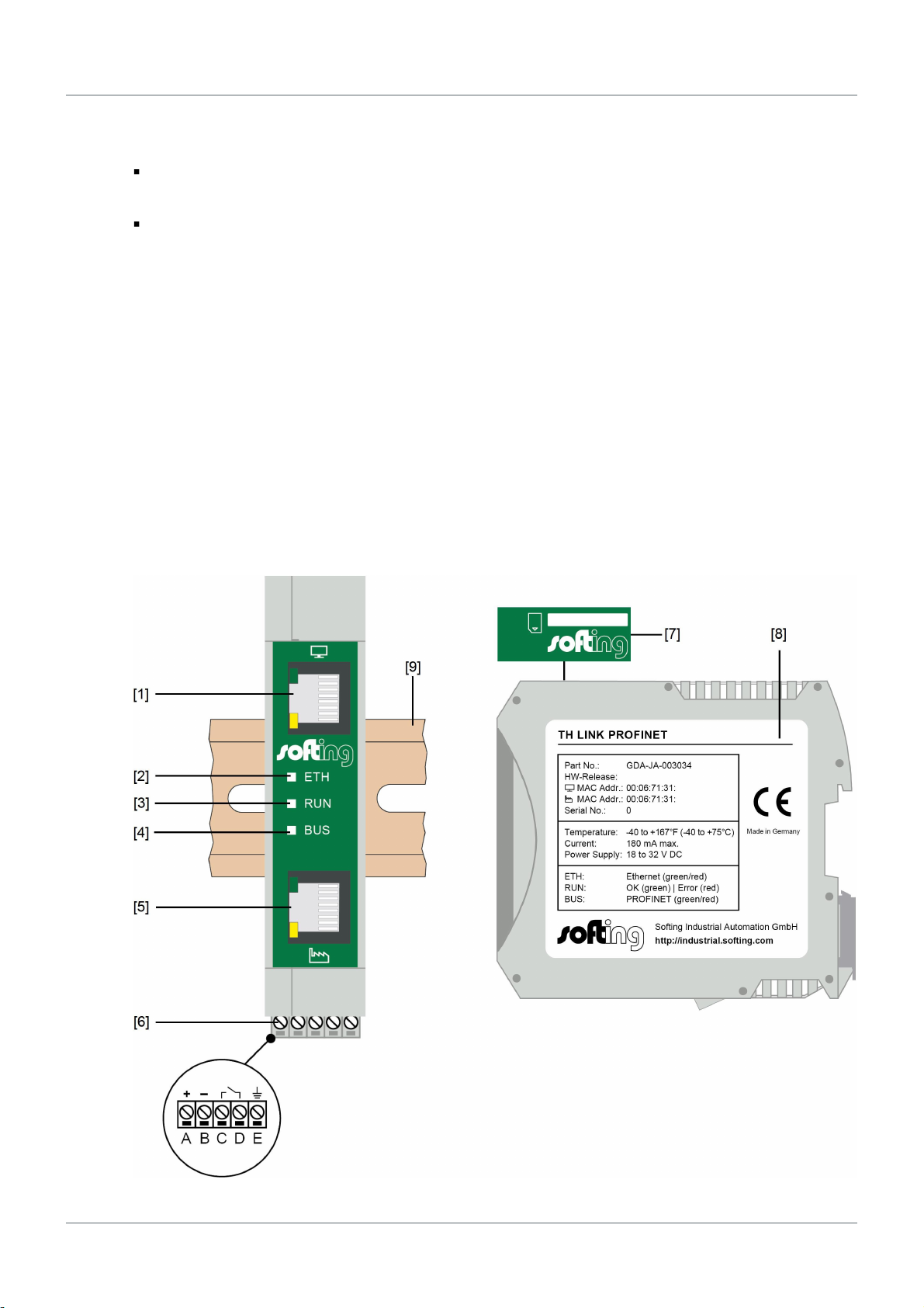
Figure 1: TH LINK (front and lateral view)
[1] Ethernet interface for office network
olights yellow: Ethernet data communication
olights green: physical connection available
[2] LED ETH
olights red: boot procedure
olights green: firmware update in progress
ois off: boot procedure is completed
[3] LED RUN
olights red: internal error
olights green: power supply is applied
ois off: device is not powered
[4] LED BUS
olights red: relay contact active (error occurred in the bus)
olights green: TH SCOPE measurement is running
ois off: TH SCOPE measurement is stopped
[5] Ethernet interface for automation network
olights yellow: Ethernet data communication
olights green: physical connection available
[6] Terminal strip for +24 V DC power supply
oA: 24 V (+)
oB: 0 V (-)
oC: Relay contact - input
oD: Relay contact - output
oE: Protective earth
[7] SD card slot
[8] Type label
2.2 Mounting
[9] 35 mm DIN rail mounting unit (not included in the delivery)

TH LINK PROFINET - Installation Manual
10 Copyright 2016 Softing Industrial Automation GmbH
2.3 SD card
TH LINK disposes of an SD card slot (refer to Connections and display elements [7]). You can save data
on the SD card to have the data available even after voltage recovery. You can find a list of
recommended SD cards in Release Notes on your installation CD or in the Softing download area
(http://industrial.softing.com/en/downloads.html).
1. Insert the SD card before installing the device or putting it into operation. Thus you make sure the
card is recognized during boot procedure.
2. Now go to TH LINK Settings TH SCOPE and set the parameter Data restore after voltage
recovery to Yes (see also TH SCOPE).
3. Following the initial device commissioning the SD card is formatted automatically. From this time
on you can save data independently from power interruptions.
Note
If the SD card is not recognized during boot procedure, restart the TH LINK.
Note
If the device power supply is interrupted, all previously saved data will be retained on the
SD card. Following a device restart the data will be read. In case the TH LINK detects a faulty
file system or no existing TH LINK structure during startup, the card will be formatted again.
The position of the blocking switch at the left card border has no effect, i.e. the card will
also be formatted or written in the blocked state.
3Start-up guideline
The following steps are required for start-up:
1. Mounting (see Mount/unmount device).
2. Plug-in SD card (recommended - see SD card).
3. Connect to network (see Connect to network).
4. Connect to the power supply (see Connecting the power supply).
5. Configure network (see Configure the device in the network).
Note
To set the IP address manually you must connect a PC to the device via crossover
cable.
4Mount/unmount device
4.1 Mount device
Note
Make sure you have a minimum of 5 cm below and above the TH LINK in order to ensure
heat dissipation.

Chapter 4 - Mount/unmount device
Copyright 2016 Softing Industrial Automation GmbH 11
Figure 2: Mount and unmount the TH LINK
[1] Device with notch on DIN rail
[2] DIN rail
[3] Device on DIN rail
[4] Stop lever
1. Place the device with its notch on the DIN rail.
2. Move the device downwards until the stop lever locks into place on the DIN rail.
4.2 Unmount device
1. Remove the connected supply and signal lines (Ethernet, power supply).
2. Place the screwdriver into the stop lever on the device (see figure above).
3. Press the screwdriver in the direction of the device and simultaneously swing the device off the DIN
rail.
5Connect to network
1. Insert the patch cable plug (RJ-45, not included in the scope of delivery) into the Ethernet socket on
the device until the plug locks into place.
2. The green LED on the Ethernet socket lights as soon as the device is energized and a network is
available.
TH LINK PROFINET - Installation Manual
12 Copyright 2016 Softing Industrial Automation GmbH
Connection options
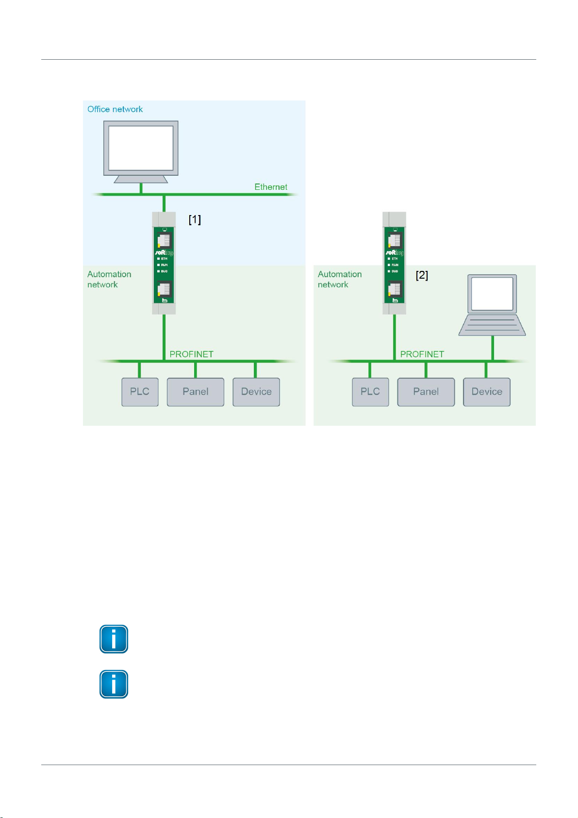
Figure 3: Connection options
1. Secure access at separated networks - connection to office network and automation network
a. At the upper Ethernet interface with the monitor icon (see figure 1 no. [1]) the office network is
connected, from which the access to the automation network should be done.
b. At the lower Ethernet interface with the factory icon (see figure 1 no. [5]) the automation
network is connected that should be monitored.
2. One network - connection to automation network only
a. Connect the TH LINK with the lower Ethernet interface with the factory icon (see figure 1 no.
[5]) in the automation network.
b. The connection of the upper Ethernet interface is not required, if the access to the TH LINK is
done from the automation network.
Note
There must be no firewall between the TH LINK and the PROFINET devices.
Note
The TH LINK does not provide any switch or router functionality.

Chapter 6 - Connecting power supply and relay contact
Copyright 2016 Softing Industrial Automation GmbH 13
6Connecting power supply and relay contact
Electrical voltage
Only qualified electricians are allowed to work on the electrical equipment.
Danger due to incorrect earthing
Incorrect device earthing may cause injury to personnel or damage the device. Ensure
correct and proper earthing of the device.
Note
Reverse polarity in the power supply can damage the device. Make sure the power supply is
connected with correct polarity.
Figure 4: Terminal strip for power supply on the device
1. Connect the cable of a 24 V power supply and the earth conductor (earth terminal) to the terminal
strip on the device. The terminal strip can be plugged and lifted out for installation using a
screwdriver.
2. Connect the cable of the circuit that should be closed by the relay contact to the terminal strip on
the device.
3. Switch on the power supply. The LED RUN is green and the LED ETH flashes red until the device's
boot procedure is completed. Afterwards the LED RUN and BUS light green.
7Configuring the device in the network
Depending on your network you have two connection options for each Ethernet interface:
Connection in a network with a DHCP server (Dynamic Host Configuration Protocol):
automatic and dynamic allocation of IP addresses (connection with patch cable via hub or switch)
Connection in a network with manual IP assignment (peer-to-peer):
manual allocation of IP addresses (connection with crossover cable)

TH LINK PROFINET - Installation Manual
14 Copyright 2016 Softing Industrial Automation GmbH
Note
One TH LINK device can monitor a range of up to 254 IP-addresses. Those IP-addresses
should all be reachable from the TH LINK device. To configure up to five different IP-ranges,
please open the settings page of the TH LINK device.
7.1 Connection in a network with DHCP server (Dynamic Host Configuration
Protocol)
The device is preset to network operation with a DHCP server and in this case it is automatically
assigned an IP address. No network configuration settings are required in this operating mode.
Note
If you connect the network whilst the boot procedure is running or completed, the DHCP
may fail to be identified. The routine for the DHCP identification only runs during device
start-up. Briefly switch off the power supply for a new DHCP identification.
7.2 Connection in a network with manual IP address assignment
If you use the device in an Ethernet network without DHCP server, you need the following for
configuration information:
TCP/IP settings for this network,
a PC/notebook with a web browser
a crossover cable between PC/notebook and TH LINK (peer-to-peer connection).
Note
Always notify your system administrator prior to allocating IP addresses.
If you set an address already assigned, other devices in the network may be deactivated and
communication may be affected.
Note
The PC/notebook must be in the same subnet as the TH LINK.
7.3 Setting new IP and network address
1. Connect the TH LINK with the upper Ethernet interface with the monitor icon (see figure 1 no. [1])
to a PC/notebook via crossover cable. The PC/notebook has to be in the same subnet as the TH
LINK (e.g. with the IP address 169.254.0.5).
2. Start a web browser on your PC/notebook.
3. Enter the IP address http://169.254.0.1 and press Enter.
4. Click Language and select English to get the user interface with English texts.
5. Click Login to log in as administrator.

Chapter 7 - Configuring the device in the network
Copyright 2016 Softing Industrial Automation GmbH 15
6. Enter the password. The default password is the nine-digit serial number of the device. You can find
it on the serial number type label on the housing or under Info.
7. Then click OK.
Note
We recommend changing the password after login (see User administration.
8. Click on Settings and then on TH LINK.
9. In menu Network configuration switch the configuration method for office networks and/or
automation networks from DHCP to Manual (see figure 5).
10. Enter the new IP address.
Note
Note down the IP address. You can only access the device's configuration page by using this
IP address.
11. Enter the new addresses for Subnet mask and Default gateway.
Note
The entry of the standard gateway is required only if you set the IP addresses for both
networks manually Otherwise, the standard gateway address is given by DHCP.

TH LINK PROFINET - Installation Manual
16 Copyright 2016 Softing Industrial Automation GmbH
12. Enter the IP address of the DNS server.
Note
The entry of the DNS server is required only if you set the IP addresses for both networks
manually Otherwise, the DNS server address is given by DHCP.
13. Click on the floppy disk sign to save the settings. The device then performs a restart.
Note
If you use several TH LINK, one TH LINK can be defined as "Parameter distributor". All TH
LINK units can receive and save the parameters after login (see Parameter distribution).
7.4 Check the connection to the device
You can check the device in the network if:
the device is integrated into the office and/or automation network.
the device is supplied with voltage.
the PC/notebook is in the office or in the automation network.
Procedure
Start a web browser on your PC/notebook.
For DHCP:
Enter the hostname http://THLINK-serial number (e.g.: http://THLINK-143500067) and press Enter.
For manual IP configuration:
Depending on the network in which your PC/notebook is installed, enter the specified IP address of
the office or automation network (basic setting: 169.254.0.1 or 169.254.0.2) and press Enter.
Now the website of the TH LINK should be displayed in the web browser.
8Network overview
With the new firmware (v4.0), the TH LINK will be provided with a new webinterface: a new network
overview tab provides a quick and essential view on the network that is being monitored by the TH
LINK device.
Detailed information about the selected TH LINK will be provided, as well as essential information
about network infrastructure, network availability, errors & failures and diagnostic entries. With that
piece of information, the user can decide whether the monitored network is in ordern, or if further
analysis (with TH SCOPE) is necessary.

Chapter 8 - Network overview
Copyright 2016 Softing Industrial Automation GmbH 17
Figure 5: TH LINK network overview tab
Note
Currently, it is only possible for PROFINET devices to distinguish between IO devices,
controllers and network devices. Network devices using EtherNet/IP or Modbus TCP
protocols will all be classified as "network devices" in the overview tab.
9Login/Logout
Note
You must be logged in as an administrator to be allowed to change settings.
9.1 Login
1. Proceed as described in Check the connection to the device.
2. Click Login.
3. Enter the password.
Note
The default password is the nine-digit serial number of the device. You can find it on the
serial number type label on the housing or under Info.
4. Then click OK.
Note
We recommend changing the password after login (see User administration).
9.2 Logout
Click Logout.

TH LINK PROFINET - Installation Manual
18 Copyright 2016 Softing Industrial Automation GmbH
10 Settings pages
10.1 TH LINK
1. Log in as administrator to change the settings (see Login).
2. Click Settings TH LINK.
The TH SCOPE settings page includes all settings for monitoring the automation network. This
includes: User administration, TH LINK description and network configuration.
Figure 6: TH LINK settings
Note
Log in as administrator to change the settings (see Login).
For detailed information about each setting, click on the question mark.

Chapter 10 - Settings pages
Copyright 2016 Softing Industrial Automation GmbH 19
10.1.1 User administration - change password
1. Log in as administrator to change the settings (see Login).
2. Click Settings TH LINK.
3. Enter the old password.
4. Select a new password and confirm it by re-entering.
5. Finally click Change password.
10.1.2 TH LINK description
Here you can enter the tag name, the location, an installation date, a description of the installed TH
LINK and the default language.
For detailed information about each setting, click on the question mark.
10.1.3 Network configuration
Here you can change the network-specific settings. These include hostname, configuration method for
office and automation network, DNS server and time server use.
For detailed information about each setting, click on the question mark.
10.2 TH SCOPE
1. Log in as administrator to change the settings (see Login).
2. Click Settings TH SCOPE.
The TH SCOPE settings page includes all settings required for monitoring the automation network.
These include settings for measurement, alerting and parameter distribution.
Note
In order to save data after a voltage recovery on an SD card, set the parameter Data restore
after voltage recovery to Yes (see also SD card).

TH LINK PROFINET - Installation Manual
20 Copyright 2016 Softing Industrial Automation GmbH
Figure 7: TH SCOPE settings
10.2.1 Measurement
The measurement settings include the type of measurement, the measurement range (default oder
user-defined ranges), start/stop of the measurement, the sorting of the diagnostics list, delete of
diagnostics messages, the additional SNMP community name, number of retries in case of no response
of the device and the startup delay.
For detailed information about each setting, click on the question mark.
10.2.2 Alert
The alerting settings include the alerting via relay contact, the email alerting, alerting interval, SMTP
server settings, email sender and receiver, subject and sending of a test email.
For detailed information about each setting, click on the question mark.
Other manuals for TH LINK PROFINET
2
Table of contents


