Indu-Sol PROFI-TM Professional User manual
Diagnostic and Service Tools for PROFIBUS
Your partner and specialist for field bus systems, Industrial Ethernet and PROFInet
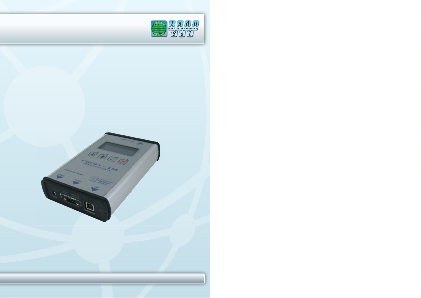
PROFI-TM Professional
USER MANUAL
Indu-Sol GmbH • Blumenstrasse 3 • D - 04626 Schmoelln • Germany
Phone: +49 34491 5818-0 • Fax: +49 34491 5818-99 • e-mail: info@indu-sol.com • www.indu-sol.com

© Copyright 2010 Indu-Sol GmbH
No part of this manual may be reproduced, photocopied, stored on a retrieval
system, transmitted, processed or translated without the express prior written
consent of Indu-Sol GmbH.
Contents
1
Introduction 6
1.1
General 6
1.2
Test Functions 6
1.3
Operating Modes of the Tool 6
1.4
PC-Software PROFIBUS Diagnostics Suite 7
2
Delivery Scope 8
3
Optional Accessories 9
3.1
D-sub adapter cable for testing live systems 9
3.2
Adapter Set for M12 Connection Technology 9
3.3
Fieldbus Shield Digital Leakage Current Clamp 9
3.4
Portable Power Supply 10
3.5
Active Measuring Point „PBMA“ IP20 – Active Terminator 11
3.5.
Active Measuring Point „PBMX“ IP67 – Active Terminator 12
4
Connectors and Controls 13
5
Power Supply and Auto Power On 14
5.1
Power-Up Behavior without USB Connection 14
5.2
Power-Up Behavior when USB Connected 15
6
Software Installation 16
6.1
Connection to a PC 16
7
Connection to PROFIBUS 16
7.1
Basics 16
7.1.1
Warning notice for testing a live bus 16
7.1.2
Connection types 17
7.1.3
Adapter cable 17
7.1.4
Strain relief 18
7.1.5
Test locations 18
7.2
Simple Connection for Tests During System Shutdown 19
7.3
Connection for Testing a Live Bus 20
7.3.1
Anschlussart D-Sub-Stecker mit Service-Buchse 21
7.3.2
Direct cable connection 22
Connection via M12 connector 23
7.4
Master Simulator and Topology Scan 23
7.4.1
Special case: Active devices at both ends of the bus 25
8
Display and Control in Stand-Alone Mode 26

8.1
Main Display 26
8.2
Operating Concept 28
8.3
Functions 29
8.3.1
Live Status function 29
8.3.1.1
Segment status 29
8.3.1.2
Station status 30
8.3.2
Quick Test function 31
8.3.3
Trend function 31
8.3.4
Master Simulator function 31
8.3.5
Settings and Help functions 32
9
Firmware Update 32
10
Maintenance and Servicing 32
11
Troubleshooting 33
12
Specifications 34
13
General Notes 35
13.1
Lithium Battery 35
13.2
CE Conformity 35
Introduction Manual
Page 6 © 2010
1 Introduction
1.1 General
The PROFI-TM Professional is a powerful tool that allows full testing of
PROFIBUS DP segments. The tool reliably detects even transient faults that
occur only sporadically.
Using the integrated master simulator, you can also test the bus if the PLC is
currently not in operation, or individually check “suspicious” bus stations.
The tool is powered either through an external AC adapter, by direct connec-
tion to 24 VDC or through an optional portable power supply unit.
1.2 Test Functions
The PROFI-TM Professional automatically detects the baud rate or open
circuit voltage as soon as you connect it to a PROFIBUS DP segment. The
following standard tests are available for simultaneously analyzing the bus
physics and bus communication:
•Quick test
•User-controlled test
•Long-term trend
Additional features (network status):
•Master simulator
•Topology scan
Expert tests (optional):
•Frame analysis
•Oscillogram analysis
•Trigger input/output
1.3 Operating Modes of the Tool
You can connect the PROFI-TM Professional to a PC or notebook, or run it in
stand-alone mode. The PC mode provides all standard and expert tests. You
can also select individual stations you want to test. The stand-alone mode
currently provides the live status and the master simulator mode. In addition,
for the future it is planned to make available the quick test and long-term trend
functions as well as the transfer of test results to the PC.
Introduction Manual
Indu-Sol GmbH Page 7
1.4 PC-Software PROFIBUS Diagnostics Suite
The PROFIBUS Diagnostics Suite allows the display and detailed analysis of
test results on the PC.
Simply connect the PROFI-TM Professional to the USB interface of a PC or
notebook. You can then use the included “PROFIBUS Diagnostics Suite” PC
software (see separate manual) to do the following:
•Perform tests and analyses
•Manage the test results with minimum effort
•Create test reports
Delivery Scope Manual
Page 8 © 2010
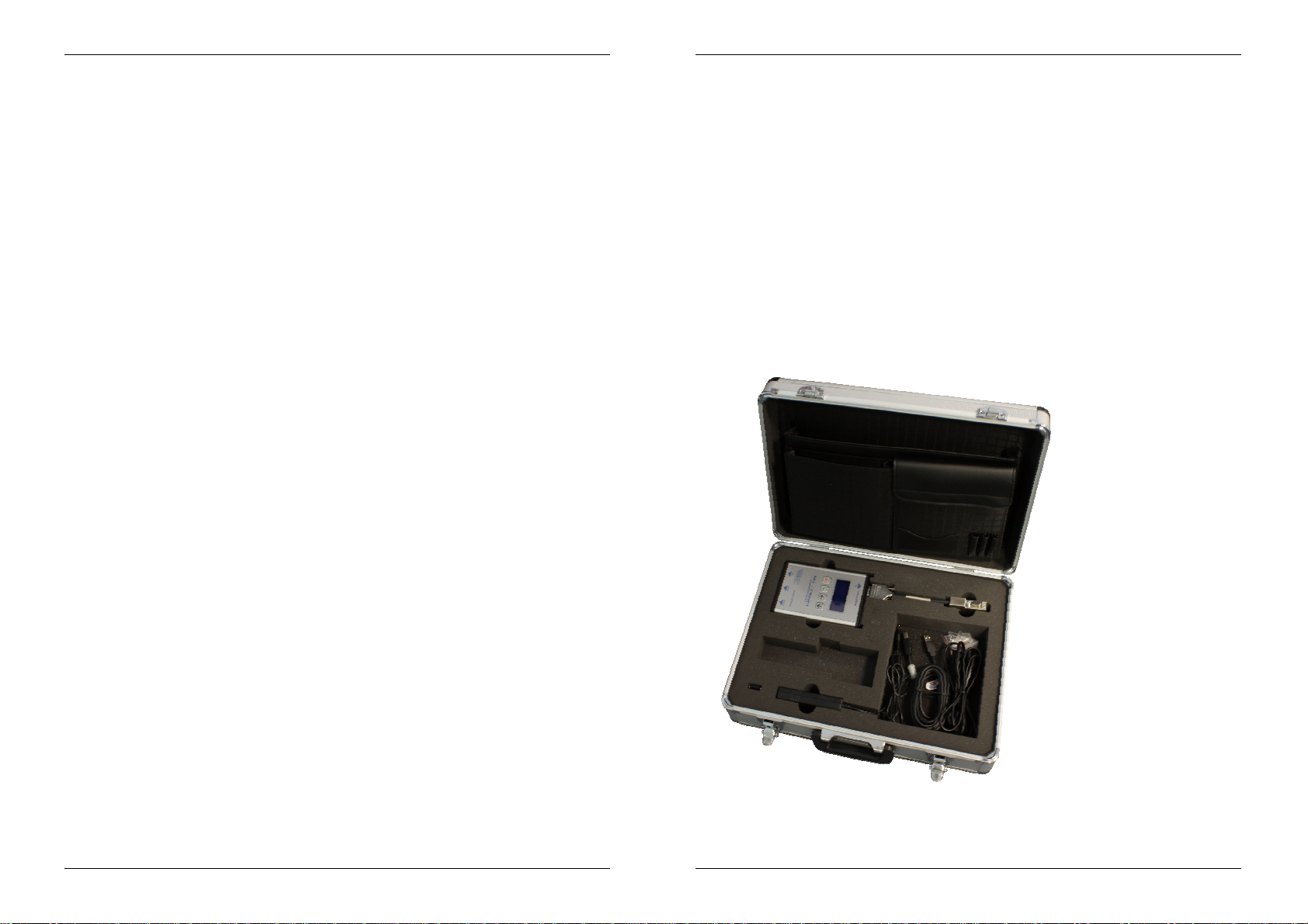
2 Delivery Scope
The PROFI-TM Professional comes in a carrying case comprising:
•Test tool with RS485 interface
•Wide-range power supply with European and US mains power cables
•Connecting cable for direct power supply with 24 VDC
•D-sub adapter cable 2 (BC-600-PB-CB-DSUB-2 for PROFIBUS DP -
blue)
•USB cable, 3 m
•Terminal block for trigger input/output
•CD-ROM with driver software, PC software and detailed integrated
help system in English and German
•PROFI-TM Professional user manual and Getting Started manual for
the PROFIBUS Diagnostics Suite PC software
PROFI-TM Professional with carrying case
Optional Accessories Manual
Indu-Sol GmbH Page 9
3 Optional Accessories
3.1 D-sub adapter cable for testing live systems
This D-sub adapter cable (BC-600-PB-CB-DSUB-1) is optimized for reduced
influence on live PROFIBUS DP segment operations. Thereby it is most
suitable for testing of running plants. The risc of critical influences on bus
operation which can cause a plant standstill is significantly reduced. Attention:
Using this cable it is not possible to use the both active functions master
simulator and topology detection (see page 22).
Fig 1: D-sub adapter cable with reduced influence on bus operation PB-DSUB-1
Order no: 00110189
3.2 Adapter Set for M12 Connection Technology
Using the M12 adapter set, you can connect the PROFI-TM Professional to
field devices with M12 connectors. The set comprises an M12 adapter cable
with special pin layout and an M12 terminating resistor that you can screw on,
if required.
Fig. 1: Special adapter for M12
Order no.: 00010580
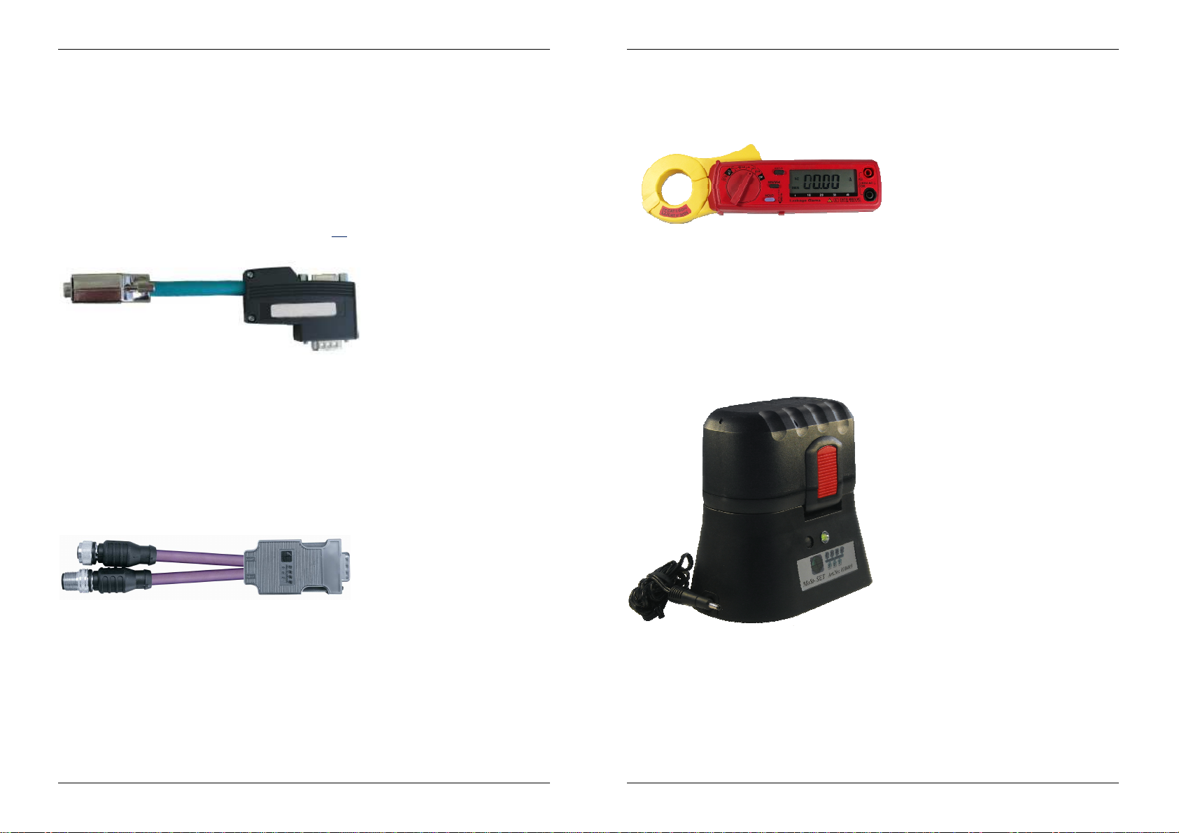
3.3 Fieldbus Shield Digital Leakage Current Clamp
When routing PROFIBUS cables in high-interference environments, electro-
magnetic interference can affect the signal quality. By measuring the shield
currents with the digital leakage current clamp, you can locate EMC problem
areas and take appropriate countermeasures. The digital leakage current
Optional Accessories Manual
Page 10 © 2010
clamp is supplied in a handy case, including measuring cables. There is also
an empty compartment for the fieldbus shield digital leakage current clamp in
the carrying case of the PROFI-TM Professional.
Fig. 2: Fieldbus Shield Digital Leakage Current Clamp PB C3
Order no.: 00010612
3.4 Portable Power Supply
The portable power supply unit allows up to 4 hours of portable operation. The
power supply kit also includes a charger and a carrying case. Attention: Mains
connector type of charger station available for Europe only.
Fig. 3: MoSt Portable Power Supply
Order no.: 00010405
Table of contents
Other Indu-Sol Diagnostic Equipment manuals


